US7898197B2 - Motor control device - Google Patents
Motor control device Download PDFInfo
- Publication number
- US7898197B2 US7898197B2 US12/178,983 US17898308A US7898197B2 US 7898197 B2 US7898197 B2 US 7898197B2 US 17898308 A US17898308 A US 17898308A US 7898197 B2 US7898197 B2 US 7898197B2
- Authority
- US
- United States
- Prior art keywords
- phase
- motor
- voltage vector
- voltage
- specified voltage
- Prior art date
- Legal status (The legal status is an assumption and is not a legal conclusion. Google has not performed a legal analysis and makes no representation as to the accuracy of the status listed.)
- Expired - Fee Related, expires
Links
Images

Classifications
-
- H—ELECTRICITY
- H02—GENERATION; CONVERSION OR DISTRIBUTION OF ELECTRIC POWER
- H02P—CONTROL OR REGULATION OF ELECTRIC MOTORS, ELECTRIC GENERATORS OR DYNAMO-ELECTRIC CONVERTERS; CONTROLLING TRANSFORMERS, REACTORS OR CHOKE COILS
- H02P21/00—Arrangements or methods for the control of electric machines by vector control, e.g. by control of field orientation
- H02P21/14—Estimation or adaptation of machine parameters, e.g. flux, current or voltage
-
- H—ELECTRICITY
- H02—GENERATION; CONVERSION OR DISTRIBUTION OF ELECTRIC POWER
- H02P—CONTROL OR REGULATION OF ELECTRIC MOTORS, ELECTRIC GENERATORS OR DYNAMO-ELECTRIC CONVERTERS; CONTROLLING TRANSFORMERS, REACTORS OR CHOKE COILS
- H02P21/00—Arrangements or methods for the control of electric machines by vector control, e.g. by control of field orientation
- H02P21/06—Rotor flux based control involving the use of rotor position or rotor speed sensors
- H02P21/10—Direct field-oriented control; Rotor flux feed-back control
-
- H—ELECTRICITY
- H02—GENERATION; CONVERSION OR DISTRIBUTION OF ELECTRIC POWER
- H02P—CONTROL OR REGULATION OF ELECTRIC MOTORS, ELECTRIC GENERATORS OR DYNAMO-ELECTRIC CONVERTERS; CONTROLLING TRANSFORMERS, REACTORS OR CHOKE COILS
- H02P21/00—Arrangements or methods for the control of electric machines by vector control, e.g. by control of field orientation
- H02P21/14—Estimation or adaptation of machine parameters, e.g. flux, current or voltage
- H02P21/141—Flux estimation
-
- H—ELECTRICITY
- H02—GENERATION; CONVERSION OR DISTRIBUTION OF ELECTRIC POWER
- H02P—CONTROL OR REGULATION OF ELECTRIC MOTORS, ELECTRIC GENERATORS OR DYNAMO-ELECTRIC CONVERTERS; CONTROLLING TRANSFORMERS, REACTORS OR CHOKE COILS
- H02P27/00—Arrangements or methods for the control of AC motors characterised by the kind of supply voltage
- H02P27/04—Arrangements or methods for the control of AC motors characterised by the kind of supply voltage using variable-frequency supply voltage, e.g. inverter or converter supply voltage
- H02P27/06—Arrangements or methods for the control of AC motors characterised by the kind of supply voltage using variable-frequency supply voltage, e.g. inverter or converter supply voltage using DC to AC converters or inverters
- H02P27/08—Arrangements or methods for the control of AC motors characterised by the kind of supply voltage using variable-frequency supply voltage, e.g. inverter or converter supply voltage using DC to AC converters or inverters with pulse width modulation
-
- H—ELECTRICITY
- H02—GENERATION; CONVERSION OR DISTRIBUTION OF ELECTRIC POWER
- H02M—APPARATUS FOR CONVERSION BETWEEN AC AND AC, BETWEEN AC AND DC, OR BETWEEN DC AND DC, AND FOR USE WITH MAINS OR SIMILAR POWER SUPPLY SYSTEMS; CONVERSION OF DC OR AC INPUT POWER INTO SURGE OUTPUT POWER; CONTROL OR REGULATION THEREOF
- H02M1/00—Details of apparatus for conversion
- H02M1/0003—Details of control, feedback or regulation circuits
- H02M1/0009—Devices or circuits for detecting current in a converter
Definitions
- the present invention relates to a motor control device for driving and controlling a motor.
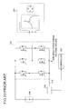
- FIG. 23 shows a general block diagram of a conventional motor driving system in which the single shunt current detecting method is adopted.
- An inverter (PWM inverter) 202 is equipped with half bridge circuits for three phases, each of which includes an upper arm and a lower arm, and it converts a DC voltage from a DC power supply 204 into a three-phase AC voltage by switching the individual arms in accordance with specified three-phase voltage values given by a controller 203 .
- the three-phase AC voltage is supplied to a three-phase permanent magnet synchronous motor 201 , so that the motor 201 is driven and controlled.
- a line connecting the individual lower arms in the inverter 202 with the DC power supply 204 is called a bus line 213 .
- a current sensor 205 transmits a signal indicating bus current that flows in the bus line 213 to the controller 203 .
- the controller 203 does sampling of an output signal of the current sensor 205 at appropriate timing so as to detect phase current of a phase in which a voltage level becomes a maximum value (maximum phase) and phase current of a phase in which a voltage level becomes a minimum value (minimum phase), i.e., current values of two phases.
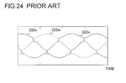
- FIG. 24 A usual correction example of a specified voltage value (pulse width) that also supports the above-mentioned correction is shown in FIG. 24 .
- the horizontal axis indicates time while 220 u , 220 v and 220 w indicate voltage levels of the U-phase, the V-phase and the W-phase, respectively. Since a voltage level of each phase follows the specified voltage value (pulse widths) for each phase, they are considered to be equivalent.
- the specified voltage value (pulse width) of each phase is corrected so that “maximum phase and intermediate phase” as well as “minimum phase and intermediate phase” of the voltage do not approach each other closer than a predetermined distance.
- voltages of individual phases do not become close to each other to the extent that current values of two phases cannot be detected, and current values of two phases can be detected stably.
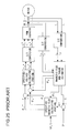
- FIG. 25 illustrates a block diagram of a general structure of the conventional motor driving system that realizes the direct torque control.
- an ⁇ -axis component ⁇ ⁇ and a ⁇ -axis component ⁇ ⁇ of a magnetic flux linkage of an armature winding of the motor are estimated based on two-phase current values (i ⁇ and i ⁇ ) obtained from two current sensors and two-phase voltage values (v ⁇ and v ⁇ ) obtained from two voltage detectors, and a generated torque T of the motor is estimated.
- a phase ⁇ S of the magnetic flux linkage vector viewed from the ⁇ -axis is calculated.
- R a represents a resistance value of a one phase of the armature winding
- P N represents the number of pole pairs of the motor
- ⁇ ⁇ ⁇ ( v ⁇ ⁇ R a i ⁇ ) dt+ ⁇ ⁇
- t 0 (A-1)
- ⁇ ⁇ ⁇ ( v ⁇ ⁇ R a i ⁇ ) dt+ ⁇ ⁇
- t 0 (A-2)
- ⁇ S tan ⁇ 1 ( ⁇ ⁇ / ⁇ ⁇ ) (A-3)
- T P N ( ⁇ ⁇ i ⁇ ⁇ ⁇ i ) (A-4)
- target values ⁇ ⁇ * and ⁇ ⁇ * of ⁇ ⁇ and ⁇ ⁇ are calculated based on a torque error ⁇ T(i.e., T* ⁇ T) between the estimated torque T and a specified torque value T*, a phase ⁇ S , and a target value
- the target values (v ⁇ * and v ⁇ *) of the two-phase voltage values (v ⁇ and v ⁇ ) are calculated so that ⁇ ⁇ and ⁇ ⁇ follow ⁇ ⁇ * and ⁇ ⁇ *, and the specified three-phase voltage values (v u *, v v * and v w *) are generated from the target values of the two-phase voltage and are supplied to the inverter.
- a motor control device includes a motor current detector for detecting motor current flowing in a three-phase motor based on current flowing between an inverter driving the motor and a DC power supply, a specified voltage vector generating portion for generating a specified voltage vector indicating a voltage vector to which an applied voltage to the motor should follow based on a magnetic flux linkage of an armature winding of the motor, a specified voltage vector correcting portion for correcting the generated specified voltage vector, and a magnetic flux estimating portion for estimating the magnetic flux linkage based on the motor current and the specified voltage vector after the correction.
- the motor control device controls the motor via the inverter in accordance with the specified voltage vector after the correction.
- the specified voltage vector generated by the specified voltage vector generating portion is a specified voltage vector on a rotating coordinate
- the specified voltage vector correcting portion corrects the specified voltage vector on the rotating coordinate in the process of converting the specified voltage vector on the rotating coordinate into specified three-phase voltage values on a three-phase fixed coordinate
- the motor control device supplies the specified three-phase voltage values corresponding to the specified voltage vector after the correction to the inverter so as to control the motor.
- the specified voltage vector generated by the specified voltage vector generating portion is a two-phase specified voltage vector on ab coordinates rotating step by step of 60 degrees of electrical angle in accordance with a phase of the specified voltage vector with respect to a predetermined fixed-axis.
- the specified voltage vector correcting portion decides whether or not the correction is necessary based on a magnitude of a coordinate axis component constituting the two-phase specified voltage vector on the ab coordinates, and if it is decided that the correction is necessary, the specified voltage vector correcting portion corrects the coordinate axis component so that the two-phase specified voltage vector on the ab coordinates is corrected.
- the motor control device further includes a coordinate converting portion for converting the two-phase specified voltage vector on the ab coordinates after the correction performed by the specified voltage vector correcting portion into a specified voltage vector on ⁇ coordinates having fixed ⁇ and ⁇ axes as its coordinate axes, and the magnetic flux estimating portion estimates the magnetic flux linkage based on the motor current and the specified voltage vector on the ⁇ coordinates.
- the motor control device further includes a coordinate converting portion for converting the two-phase specified voltage vector on the ab coordinates after the correction performed by the specified voltage vector correcting portion into a specified voltage vector on ⁇ coordinates having fixed ⁇ and ⁇ axes as its coordinate axes, and the magnetic flux estimating portion estimates coordinate axis components of the magnetic flux linkage on the ⁇ coordinates based on coordinate axis components of the motor current on the ⁇ coordinates and the specified voltage vector on the ⁇ coordinates.
- the motor control device further includes a torque estimating portion for estimating a torque generated by the motor based on the motor current and the estimated magnetic flux linkage, and the motor control device performs direct torque control of the motor based on the estimated torque.
- the motor control device further includes a rotor position estimating portion for estimating a rotor position of the motor based on the estimated magnetic flux linkage, and the motor control device performs vector control of the motor based on the estimated rotor position.
- a motor driving system includes a three-phase motor, an inverter for driving the motor, and the above-mentioned motor control device for controlling the inverter so as to control the motor.
- FIG. 1 is a block diagram of a general structure of a motor driving system according to an embodiment of the present invention.
- FIG. 2 is a diagram illustrating a typical example of three-phase AC voltage to be applied to the motor shown in FIG. 1 .
- FIG. 3 is a diagram of a table showing a relationship between energizing patterns of the motor shown in FIG. 1 and bus current.
- FIG. 4 is a diagram illustrating a relationship between a voltage level of each phase voltage and a carrier signal in the motor shown FIG. 1 and waveforms of a PWM signal and bus current corresponding to the relationship.
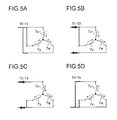
- FIGS. 5 A-5D are equivalent circuit diagrams of armature windings and a periphery thereof shown in FIG. 1 at each timing shown in FIG. 4 .
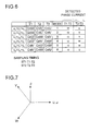
- FIG. 6 is a diagram of a table showing combinations (modes) of a relationship of phase voltage levels in the motor shown in FIG. 1 and phases of current detected in the combinations.
- FIG. 7 is a diagram illustrating a relationship among a U-phase axis, a V-phase axis, a W-phase axis, the ⁇ -axis and the ⁇ -axis.
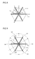
- FIG. 8 is a space vector diagram illustrating a relationship among the U-phase axis, the V-phase axis, the W-phase axis, the ⁇ -axis, the ⁇ -axis and the voltage vector according to a first example of the present invention.
- FIG. 9 is a diagram for explaining an a-axis defined in the embodiment of the present invention.
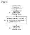
- FIG. 10 is a flowchart showing a procedure of a correction process of the voltage vector according to the embodiment of the present invention.
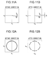
- FIG. 11A is a diagram illustrating a voltage vector locus on the ab coordinates before the correction process shown in FIG. 10 .
- FIG. 11B is a diagram illustrating the voltage vector locus on the ab coordinates after the correction process shown in FIG. 10 .
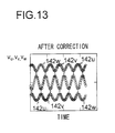
- FIG. 12A is a diagram illustrating a voltage vector locus on the ⁇ coordinates before the correction process shown in FIG. 10 .
- FIG. 12B is a diagram illustrating the voltage vector locus on the ⁇ coordinates after the correction process shown in FIG. 10 .
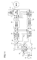
- FIG. 13 is a diagram illustrating voltage waveforms of the U-phase voltage, the V-phase voltage and the W-phase voltage obtained after the correction process shown in FIG. 10 .
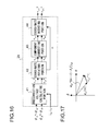
- FIG. 14 is a block diagram of a structure of a motor driving system according to a first example of the present invention.
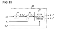
- FIG. 15 is an internal block diagram of a specified magnetic flux calculating portion shown in FIG. 14 .
- FIG. 16 is an internal block diagram of a specified voltage calculating portion shown in FIG. 14 .
- FIG. 17 is a vector diagram showing a relationship between the magnetic flux linkage and the voltage concerned with the calculation in the specified voltage calculating portion shown in FIG. 14 .
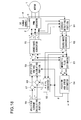
- FIG. 18 is a block diagram illustrating a structure of a motor driving system according to a second example of the present invention.
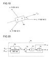
- FIG. 19 is a diagram illustrating a relationship among the U-phase axis, the V-phase axis, the W-phase axis and the d-axis.
- FIG. 20 is an internal block diagram of a position and speed estimator shown in FIG. 18 .
- FIG. 21 is an internal block diagram of a specified voltage calculating portion shown in FIG. 18 .
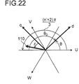
- FIG. 22 is a diagram illustrating a rotor phase ( ⁇ ) decomposed by considering a relationship with the a-axis shown in FIG. 9 .
- FIG. 23 is a block diagram illustrating a general structure of a conventional motor driving system adopting the single shunt current detecting method.
- FIG. 24 is a diagram illustrating a correction example of the specified voltage value (pulse width) in the conventional case where the single shunt current detecting method is adopted.
- FIG. 25 is a block diagram illustrating a general structure of a conventional motor driving system that realizes a direct torque control.
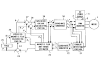
- FIG. 1 is a block structural diagram of a motor driving system according to an embodiment of the present invention.
- the motor driving system shown in FIG. 1 includes a three-phase permanent magnet synchronous motor 1 (hereinafter referred to as a “motor 1” simply), a PWM (Pulse Width Modulation) inverter 2 (hereinafter referred to as an “inverter 2” simply), a controller 3 , a DC power supply 4 and a current sensor 5 .
- the DC power supply 4 delivers a DC voltage between a positive output terminal 4 a and a negative output terminal 4 b so that the negative output terminal 4 b becomes a low voltage side.
- the motor driving system shown in FIG. 1 adopts a single shunt current detecting method.
- the motor 1 includes a rotor 6 to which a permanent magnet is provided and a stator 7 to which armature windings 7 u , 7 v and 7 w of U-phase, V-phase and W-phase are provided.
- the armature windings 7 u , 7 v and 7 w are connected at a neutral point 14 as a center in a form of Y-connection. Non-connection ends of the armature windings 7 u , 7 v and 7 w that are opposite ends of the neutral point 14 are connected to terminals 12 u , 12 v and 12 w , respectively.
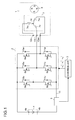
- the inverter 2 is provided with a half bridge circuit for the U-phase, a half bridge circuit for the V-phase and a half bridge circuit for the W-phase.
- Each of the half bridge circuits includes a pair of switching elements.
- the pair of switching elements are connected in series between the positive output terminal 4 a and the negative output terminal 4 b of the DC power supply 4 , so that each of the half bridge circuits is supplied with a DC voltage from the DC power supply 4 .
- the half bridge circuit for the U-phase is made up of a high voltage side switching element 8 u (hereinafter referred to as an upper arm 8 u , too) and a low voltage side switching element 9 u (hereinafter referred to as a lower arm 9 u , too).
- the half bridge circuit for the V-phase is made up of a high voltage side switching element 8 v (hereinafter referred to as an upper arm 8 v , too) and a low voltage side switching element 9 v (hereinafter referred to as a lower arm 9 v , too).
- the half bridge circuit for the W-phase is made up of a high voltage side switching element 8 w (hereinafter referred to as an upper arm 8 w , too) and a low voltage side switching element 9 w (hereinafter referred to as a lower arm 9 w , too).
- the switching elements 8 u , 8 v , 8 w , 9 u , 9 v and 9 w are respectively connected to diodes 10 u , 10 v , 10 w , 11 u , 11 v and 11 w in parallel so that the direction from the low voltage side to the high voltage side of the DC power supply 4 becomes the forward direction.
- Each of the diodes works as a freewheel diode.
- connection node of the upper arm 8 u and the lower arm 9 u that are connected in series, the connection node of the upper arm 8 v and the lower arm 9 v that are connected in series, the connection node of the upper arm 8 w and the lower arm 9 w that are connected in series are connected to the terminals 12 u , 12 v and 12 w , respectively.
- field-effect transistors are shown as the switching elements in FIG. 1 , but they can be replaced with IGBTs (Insulated Gate Bipolar Transistors) or the like.
- the inverter 2 generates a PWM (Pulse Width Modulation) signal for each phase based on the specified three-phase voltage values supplied from the controller 3 and supplies the PWM signal to a control terminal (base or gate) of each switching element in the inverter 2 , so that each switching element performs switching action.
- the specified three-phase voltage values that are supplied from the controller 3 to the inverter 2 include a U-phase specified voltage value v u *, a V-phase specified voltage value v v * and a W-phase specified voltage value v w *.
- the specified voltage values v u *, v v * and v w * represent voltage levels (voltage values) of the U-phase voltage v u , V-phase voltage v v and W-phase voltage v w , respectively.
- the U-phase voltage v u , the V-phase voltage v v and the W-phase voltage v w represent respectively voltages at the terminals 12 u , 12 v and 12 w viewed from the neutral point 14 shown in FIG. 1 .
- the inverter 2 controls on (conducting state) or off (nonconducting state) of the switching elements based on the specified voltage values v u *, v v * and v w *.
- the upper arm is on when the lower arm is off in each half bridge circuit. On the contrary, the upper arm is off when the lower arm is on. In the following description, the above-mentioned dead time will be ignored.
- the DC voltage applied to the inverter 2 by the DC power supply 4 is converted into a three-phase AC voltage that is PWM-modulated (pulse width modulated), for example, by the switching action of the switching elements in the inverter 2 .
- PWM-modulated pulse width modulated
- the current sensor 5 senses current that flows in a bus line 13 of the inverter 2 (hereinafter referred to as “bus current”).
- the bus current includes a DC component, so it may be regarded as DC current.
- the low voltage sides of the lower arms 9 u , 9 v and 9 w are connected together to the negative output terminal 4 b of the DC power supply 4 .
- the wiring line to which the low voltage sides of the lower arms 9 u , 9 v and 9 w are connected together is the bus line 13 , and the current sensor 5 is inserted in the bus line 13 in series.
- the current sensor 5 transmits a signal indicating a current value of the bus current (detention current) to the controller 3 .
- the controller 3 refers to an output signal of the current sensor 5 and the like so as to generate and deliver the above-mentioned specified three-phase voltage values.
- the current sensor 5 is a shunt resistor, a current transformer or the like, for example.
- phase current (see FIG. 1 ).
- a polarity of the current direction flowing from the terminal 12 u , 12 v or 12 w to the neutral point 14 is regarded as positive, while a polarity of the current direction flowing from the neutral point 14 outward is regarded as negative.
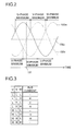
- FIG. 2 shows a typical example of the three-phase AC voltage that is applied to the motor 1 .
- references 100 u , 100 v and 100 w show waveforms of the U-phase voltage, the V-phase voltage and the W-phase voltage to be applied to the motor 1 , respectively.
- Each of the U-phase voltage, the V-phase voltage and the W-phase voltage (or a generic name of them) is referred to as phase voltage.
- an output voltage of the inverter 2 should be a sine wave.
- each of the phase voltages shown in FIG. 2 is an ideal sine wave, a distortion is added to the sine wave in the present embodiment (as described later in detail).
- FIG. 2 a relationship among the voltage levels of the U-phase voltage, the V-phase voltage and the W-phase voltage alters as time passes. This relationship is determined by the specified three-phase voltage values, and the inverter 2 decides an energizing pattern for each phase in accordance with the specified three-phase voltage values.
- FIG. 3 shows this energizing pattern as a table. In FIG. 3 , the first to the third columns from the left side indicate the energizing pattern. The fourth column will be described later.
- the energizing pattern includes:
- LHH an energizing pattern “LHH” in which the upper arms of the V and W-phases are turned on while the lower arm of the U-phase is turned on;
- HLL an energizing pattern in which the upper arm of the U-phase is turned on while the lower arms of the V and W-phases are turned on;
- HSH an energizing pattern in which the upper arms of the U and W-phases are turned on while the lower arm of the V-phase is turned on;
- HHL an energizing pattern in which the upper arms of the U and V-phases are turned on while the lower arm of the W-phase is turned on;
- HHH an energizing pattern “HHH” in which all the upper arms of the U, V and W-phases are turned on (references of the upper arms and the lower arms ( 8 u and the like) are omitted).
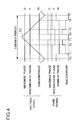
- FIG. 4 shows a relationship between a voltage level of each phase voltage and a carrier signal in the case where three-phase modulation is performed and waveforms of the PWM signal and bus current corresponding to the relationship.
- the relationship between voltage levels of the individual phase voltages changes variously, but FIG. 4 shows it by noting a certain timing 101 shown in FIG. 2 for concrete description. More specifically, FIG. 4 shows the case where a voltage level of the U-phase voltage is the maximum, and a voltage level of the W-phase voltage is the minimum.
- phase having the maximum voltage level is referred to as a “maximum phase”
- the phase having the minimum voltage level is referred to as a “minimum phase”
- the phase whose voltage level is not the maximum or the minimum is referred to as an “intermediate phase”.
- the maximum phase, the intermediate phase and the minimum phase are the U-phase, the V-phase and the W-phase, respectively.
- reference CS denotes a carrier signal that is compared with a voltage level of each phase voltage.
- the carrier signal is a periodical signal of a triangular wave, and the period of the signal is referred to as a carrier period. Note that the carrier period is much shorter than a period of the three-phase AC voltage shown in FIG. 2 . Therefore, if the triangular wave of the carrier signal shown in FIG. 4 is added to the diagram of FIG. 2 , the triangular wave will look like a single line.
- FIGS. 5A-5D are equivalent circuit diagrams of the armature windings and a periphery thereof at individual timings shown in FIG. 4 .
- a start timing of each carrier period i.e., the timing when the carrier signal is a lowest level is referred to as T 0 .
- T 0 the timing when the carrier signal is a lowest level is referred to as T 0 .
- the upper arms ( 8 u , 8 v and 8 w ) of the individual phases are turned on.
- a short circuit is formed so that current from or to the DC power supply 4 becomes zero. Therefore, the bus current becomes zero.
- the inverter 2 refers to v u *, v v * and v w * so as to compare a voltage level of each phase voltage with the carrier signal.
- a level of the carrier signal voltage level
- the lower arm of the minimum phase is turned on.
- current of the minimum phase flows as the bus current.
- the lower arm 9 w of the W-phase is in the turned-on state during the period from the timing T 1 to a timing T 2 that will be described later. Therefore, the W-phase current (having negative polarity) flows as the bus current.
- the carrier signal reaches the maximum level, and then a level of the carrier signal decreases.
- the states as shown in FIGS. 5D , 5 C, 5 B and 5 A appear one by one in this order. More specifically, in the decreasing process of a level of the carrier signal, it is supposed that a voltage level of the maximum phase crosses the carrier signal at the timing T 4 , a voltage level of the intermediate phase crosses the carrier signal at a timing T 5 , a voltage level of the minimum phase crosses the carrier signal at a timing T 6 , and a next carrier period starts at a timing T 7 .
- the period between the timing T 4 and the timing T 5 , the period between the timing T 5 and the timing T 6 , the period between the timing T 6 and the timing T 7 have the same energizing patterns as the period T 2 -T 3 , the period T 1 -T 2 and the period T 0 -T 1 , respectively.
- the minimum phase current can be detected from the bus current. If the bus current is sensed in the period T 2 -T 3 or T 4 -T 5 , the maximum phase current can be detected from the bus current. Then, the intermediate phase current can be obtained by calculation utilizing the fact that a sum of the three phase current values becomes zero.
- the fourth column in the table shown in FIG. 3 indicates a phase of current that flows as the bus current in each energizing pattern with a polarity of the current. For example, in the energizing pattern “HHL” corresponding to the eighth row in the table shown in FIG. 3 , the W-phase current (having negative polarity) flows as the bus current.
- the period obtained by removing the period between the timing T 1 and the timing T 6 from the carrier period indicates a pulse width of the PWM signal for the minimum phase.
- the period obtained by removing the period between the timing T 2 and the timing T 5 from the carrier period indicates a pulse width of the PWM signal for the intermediate phase.
- the period obtained by removing the period between the timing T 3 and the timing T 4 from the carrier period indicates a pulse width of the PWM signal for the maximum phase.
- FIG. 6 shows the combinations as a table.
- the U-phase voltage, the V-phase voltage and the W-phase voltage are denoted by v u , v v and v w , respectively,
- FIGS. 4 and 5 A- 5 D correspond to the first mode.
- FIG. 6 also indicates a phase of current sensed in each mode.
- the U-phase specified voltage value v u *, the V-phase specified voltage value v v * and the W-phase specified voltage value v w * are specifically shown as set values of counter CntU, CntV and CntW, respectively.
- a larger set value is assigned to a higher phase voltage. For example, “CntU>CntV>CntW” holds in the first mode.
- the counter (not shown) that is provided to the controller 3 increments its count value from zero every carrier period with reference to the timing T 0 .
- the count value reaches CntW
- the state in which the upper arm 8 w of the W-phase is turned on is switched to the state in which the lower arm 9 w is turned on.
- the count value reaches CntV
- the state in which the upper arm 8 v of the V-phase is turned on is switched to the state in which the lower arm 9 v is turned on.
- the count value reaches CntU
- the state in which the upper arm 8 u of the U-phase is turned on is switched to the state in which the lower arm 9 u is turned on.
- the count value is decremented so that the switching action is performed reversely.
- the timing when the above-mentioned counter value reaches CntW corresponds to the timing T 1 .
- the timing when it reaches CntV corresponds to the timing T 2 .
- the timing when it reaches CntU corresponds to the timing T 3 .
- the output signal of the current sensor 5 is sampled at a timing when the counter value is larger than CntW and is smaller than CntV, so that the W-phase current (having negative polarity) flowing as the bus current can be detected.
- the output signal of the current sensor 5 is sampled at a timing when the counter value is larger than CntV and is smaller than CntU, so that the U-phase current (having positive polarity) flowing as the bus current can be detected.
- the timing when the above-mentioned counter value reaches CntW corresponds to the timing T 1 .
- the timing when it reaches CntU corresponds to the timing T 2 .
- the timing when it reaches CntV corresponds to the timing T 3 .
- the W-phase current (having negative polarity) can be detected from the bus current at the timing when the counter value is larger than CntW and is smaller than CntU.
- the V-phase current (having positive polarity) can be detected from the bus current at the timing when the counter value is larger than CntU and is smaller than CntV.
- sampling timing for sensing phase current of the minimum phase in the period T 1 -T 2 (e.g., mid-term between the timing T 1 and the timing T 2 ) is denoted by ST 1
- sampling timing for sensing phase current of the maximum phase in the period T 2 -T 3 (e.g., mid-term between the timing T 2 and the timing T 3 ) is denoted by ST 2 .
- a pulse width (and a duty factor) of the PWM signal for each phase is specified by the set values CntU, CnuV and CntW of the counter as the specified three-phase voltage values (v u *, v v * and v w *).
- phase current of the minimum phase cannot be sensed. If the current values of two phases cannot be measured, phase current of three phases cannot be reproduced. As a result, a vector control of the motor 1 cannot be performed.
- a voltage vector indicating an applied voltage to the motor 1 (specified voltage vector) is corrected so that a voltage level difference between the phase voltages is maintained to be larger than a predetermined value in the period in which it is considered that current values of two phases cannot be measured.
- FIG. 7 shows a relationship among the U-phase axis, the V-phase axis and the W-phase axis that are armature winding fixed axes of the U-phase, the V-phase and the W-phase, and the ⁇ -axis and the ⁇ -axis that are perpendicular to each other.
- a phase of the V-phase axis leads by 120 degrees of electrical angle with respect to the U-phase axis
- a phase of the W-phase axis leads by 120 degrees of electrical angle with respect to the V-phase axis.
- the counterclockwise direction corresponds to the leading direction of the phase.
- the ⁇ -axis matches with the U-phase axis, and the ⁇ -axis leads by 90 degrees of electrical angle with respect to the ⁇ -axis.
- the U-phase axis, the V-phase axis, the W-phase axis, the ⁇ -axis and the ⁇ -axis are fixed axes having no relationship with rotation of the rotor 6 .
- coordinates (coordinate system) having the ⁇ -axis and the ⁇ -axis selected as the coordinate axes are referred to as ⁇ coordinates ( ⁇ coordinate system).
- a whole motor voltage that is applied to the motor 1 from the inverter 2 is denoted by V a
- a whole motor current that is supplied to the motor 1 from the inverter 2 is denoted by I a .
- an ⁇ -axis component and a ⁇ -axis component of the motor voltage V a are expressed as an ⁇ -axis voltage v ⁇ and a ⁇ -axis voltage v ⁇ , respectively.
- An ⁇ -axis component and a ⁇ -axis component of the motor current I a are expressed as an ⁇ -axis current i ⁇ and a ⁇ -axis current i ⁇ , respectively.
- a U-phase axis component, a V-phase axis component and a W-phase axis component of the motor voltage V a are expressed as a U-phase voltage v u , a V-phase voltage v v and a W-phase voltage v w , respectively.
- a U-phase axis component, a V-phase axis component and a W-phase axis component of the motor current I a are expressed as a U-phase current i u , a V-phase current i v and a W-phase current i w , respectively.
- FIG. 8 illustrates a space vector diagram indicating a relationship among the U-phase axis, the V-phase axis, the W-phase axis, the ⁇ -axis, the ⁇ -axis and the voltage vector.
- the vector denoted by numeral 110 is the voltage vector.
- a phase of the voltage vector 110 viewed from the ⁇ -axis in the counterclockwise direction is denoted by ⁇ ⁇
- a phase of the voltage vector 110 viewed from the ⁇ -axis in the counterclockwise direction is denoted by ⁇ ⁇ .
- An angle quantity (n ⁇ /3) shown in FIG. 8 will be described later.
- the voltage vector 110 is the voltage (motor voltage V a ) applied to the motor 1 , which is expressed as a two-dimensional vector quantity. For example, noting the ⁇ coordinates, the ⁇ -axis component and the ⁇ -axis component of the voltage vector 110 are v ⁇ and v ⁇ , respectively. Actually, an ⁇ -axis specified voltage value and a ⁇ -axis specified voltage value indicating target values of the ⁇ -axis voltage and the ⁇ -axis voltage in the motor driving system are calculated, which express the voltage vector 110 . Therefore, the voltage vector is also translated into the specified voltage vector.
- An asterisk region 111 with hatching that includes a vicinity of the U-phase axis, a vicinity of the V-phase axis and a vicinity of the W-phase axis indicates the region where current values of two phases cannot be detected. For example, if the V-phase voltage and the W-phase voltage are close to each other so that current values of two phases cannot be detected, the voltage vector 110 is located at a vicinity of the U-phase axis. If the U-phase voltage and the W-phase voltage are close to each other so that current values of two phases cannot be detected, the voltage vector 110 is located at a vicinity of the V-phase axis.
- the region 111 where current values of two phases cannot be detected exist every 60 degrees of electrical angle with reference to the U-phase axis. If the voltage vector 110 exists in the region 111 , the current values of two phases cannot be detected. Therefore, if the voltage vector exists in the region 111 , the voltage vector should be corrected so that the voltage vector becomes a vector outside the region 111 .
- the a-axis becomes any one of a 1 to a 6 axes in accordance with a phase of the voltage vector 110 with respect to a predetermined fixed-axis. It is supposed that this predetermined fixed-axis is the U-phase axis (i.e., the ⁇ -axis ). Then, the a-axis becomes any one of a 1 to a 6 axes in accordance with the phase ⁇ ⁇ .
- the a 1 axis, the a 3 axis and the a 5 axis match the U-phase axis, the V-phase axis and the W-phase axis, respectively.
- the a 2 axis, the a 4 axis and the a 6 axis match respectively an intermediate axis between the a 1 axis and the a 3 axis, an intermediate axis between the a 3 axis and the a 5 axis, and an intermediate axis between the a 5 axis and the a 1 axis. Note that a circle denoted by reference 131 will be described later.
- the a-axis becomes the a 1 axis.
- the a-axis becomes the a 2 axis.
- the a-axis becomes the a 3 axis.
- the a-axis becomes the a 4 axis.
- the a-axis becomes the a 5 axis.
- the a-axis becomes the a 6 axis.
- the a-axis becomes the a 4 axis.
- the a-axis rotates in a stepping manner every 60 degrees along with rotation of the voltage vector
- the b-axis also rotates in a stepping manner every 60 degrees together with the a-axis that is orthogonal to the b-axis.
- the a-axis and the b-axis can be expressed to be coordinate axes that are digitized every 60 degrees and rotate every 60 degrees. For this reason, the a-axis is always located at the center of the region where current values of two phases cannot be detected.
- a voltage vector on the dq coordinates is converted into that on the ab coordinates.
- the a-axis component and the b-axis component of the voltage vector converted into that on the ab coordinates are referred to and are corrected if necessary (for instance, the b-axis component is increased by the correction).
- a phase of the axis to which the voltage vector 110 is closest among the a 1 to a 6 axes is expressed by (n ⁇ /3) with reference to the U-phase axis (see FIG. 8 ).
- n is a quotient that is obtained by dividing ( ⁇ ⁇ +2 ⁇ /3) by ⁇ /3 or a quotient that is obtained by dividing ( ⁇ ⁇ + ⁇ /6) by ⁇ /3.
- the quotient is an integer of a value obtained by dividing a dividend by a divisor, when a remainder is omitted.
- ⁇ ⁇ and ⁇ ⁇ can be calculated in accordance with the equations (1-1a) and (1-1b) below.
- ⁇ ⁇ tan ⁇ 1 ( ⁇ v ⁇ /v ⁇ ) (1-1a)
- ⁇ ⁇ tan ⁇ 1 ( v ⁇ /v ⁇ ) (1-1b)
- the ab coordinates correspond to coordinates obtained by rotating the ⁇ coordinates by an angle (n ⁇ /3). Therefore, regarding that the voltage vector 110 is a voltage vector on the ab coordinates and that the a-axis component and the b-axis component of the voltage vector 110 are the a-axis voltage v a and the b-axis voltage v b , the ⁇ -axis voltage v ⁇ , the ⁇ -axis voltage v ⁇ , the a-axis voltage v a and the b-axis voltage v b satisfy the coordinate conversion equation (1-2) below.
- [ v a v b ] [ cos ⁇ ⁇ ( - n ⁇ ⁇ ⁇ / 3 ) - sin ⁇ ⁇ ( - n ⁇ ⁇ ⁇ / 3 ) sin ⁇ ⁇ ( - n ⁇ ⁇ ⁇ / 3 ) cos ⁇ ( - n ⁇ ⁇ ⁇ / 3 ) ] ⁇ [ v ⁇ v ⁇ ] ( 1 ⁇ - ⁇ 2 )
- FIG. 10 shows a flowchart indicating a procedure of this correction process.
- the coordinate conversion is performed in accordance with the equation (1-2).
- the correction process with respect to v a and v b is performed.
- step S 2 it is decided first whether or not a value that indicates an amplitude of the b-axis voltage v b (i.e., an absolute value of the b-axis voltage v b ) is smaller than a predetermined threshold value ⁇ (here, ⁇ >0). In other words, it is decided whether or not the expression (1-3) as below is satisfied. Further, if the absolute value of the b-axis voltage v b is smaller than the threshold value ⁇ and the b-axis voltage v b is positive, the correction is performed so that v b equals ⁇ .
- the correction is performed so that v b equals ( ⁇ ). If the absolute value of the b-axis voltage v b is more than or equal to the threshold value ⁇ , the correction is not performed with respect to v b .
- step S 2 it is also decided whether or not the a-axis voltage v a satisfies the equation (1-4) below. If it satisfies the equation (1-4), the correction of v a is performed so that v a becomes equal to the right side of the equation (1-4). If v a does not satisfy the equation (1-4) below, the correction is not performed with respect to v a .
- the equation (1-4) is used for deciding whether the voltage vector 110 is included inside the circle 131 shown in FIG. 9 .
- the state where the voltage vector 110 is included inside the circle 131 corresponds to the state where the phase voltages of three phases are close to each other. In this state, the current values of two phases cannot be detected regardless of a value of the b-axis voltage v b .
- FIGS. 11A and 11B illustrate a locus of the voltage vector ( 110 ) on the ab coordinates before and after the correction process performed in the step S 2 .
- FIG. 11 A shows a voltage vector locus on the ab coordinates before the correction
- FIG. 11B shows a voltage vector locus on the ab coordinates after the correction.
- FIGS. 11A and 11B exemplify a case where the b-axis voltage is corrected.
- FIGS. 11A and 11B illustrates a lot of plotted dots indicating voltage values at individual timings.
- the voltage vector before the correction corresponding to FIG. 11A can be located at a vicinity of the a-axis where current values of two phases cannot be detected, but the voltage vector after the correction corresponding to FIG. 11B is not located at a vicinity of the a-axis by the correction with respect to v b .
- the process goes to the step S 3 where the voltage vector 110 after the correction on the ab coordinates is converted into the voltage vector 110 on the ⁇ coordinates.
- the ⁇ -axis component and the ⁇ -axis component of the voltage vector 110 after the correction process in the step S 2 are denoted respectively by v ⁇ c and v ⁇ c , the coordinate conversion in the step S 3 is performed in accordance with the equation (1-5).
- FIGS. 12A and 12B illustrate a locus of the voltage vector ( 110 ) on the ⁇ coordinates before and after the correction process described above.
- FIG. 12A shows a voltage vector locus on the ⁇ coordinates before the correction
- FIG. 12B shows a voltage vector locus on the ⁇ coordinates after the correction.
- This correction process makes a region where a voltage vector is not located exist every 60 degrees of electrical angle in the ⁇ coordinates as fixed coordinates.
- the voltage vector (specified voltage vector) after the correction is converted into individual voltage components of the U-phase, the V-phase and the W-phase finally.
- FIG. 12A shows a voltage vector locus on the ⁇ coordinates before the correction
- FIG. 12B shows a voltage vector locus on the ⁇ coordinates after the correction.
- FIG. 13 illustrates waveforms of voltages v u , v v and v w obtained after the above-mentioned correction process, in which the horizontal axis represents time.
- plotted dots 142 u arranged on a distorted sine wave shows a locus of the voltage v u
- plotted dots 142 v arranged on a distorted sine wave shows a locus of the voltage v v
- plotted dots 142 w arranged on a distorted sine wave shows a locus of the voltage v w .
- a voltage difference between phase voltages is secured to be larger than a predetermined value by the above-mentioned correction process.
- first and second examples are described as examples to which the correction process (correction method) described above is applied. Note that items described in one example (e.g., the first example) can be applied to another example, as long as no contradiction arises.
- FIG. 14 is a block diagram illustrating a structure of a motor driving system according to the first example.
- so-called direct torque control is performed.
- magnetic flux of a permanent magnet or an inductance distribution may have harmonics in many cases.
- the magnetic flux of the permanent magnet linking with the U-phase armature winding traces a waveform of a sine wave with respect to a change in rotor phase ideally, but actually the waveform includes harmonics, which causes a distortion of an induction voltage (electromotive force) generated by rotation of the permanent magnet.
- a d-axis inductance and a q-axis inductance of the armature winding also include harmonics. It is known that such harmonics can cause a torque ripple.
- the generated torque becomes constant if the magnetic flux of the permanent magnet and the inductance distribution have no harmonic. Actually, however, they usually have harmonics, so the generated torque has a ripple.
- the direct torque control the magnetic flux linking with the armature winding of the stator is estimated, and a torque is estimated based on the estimated magnetic flux and the motor current so that the torque is controlled directly. Since the estimated magnetic flux is affected by the harmonics, the estimation of the torque is also affected by the harmonics. Since the direct torque control is performed based on the estimated torque, the torque ripple can be reduced even if the magnetic flux of the permanent magnet or the inductance distribution has harmonics.
- a motor control system shown in FIG. 14 includes a motor 1 , an inverter 2 , a DC power supply 4 and a current sensor 5 . It also includes individual portions denoted by reference numerals 21 to 30 . In the first example, the controller 3 shown in FIG. 1 is made up of individual portions denoted by reference numerals 21 to 30 .
- the current sensor 5 senses the bus current and outputs a signal indicating a current value of the bus current.
- a current detecting portion 21 refers to the specified three-phase voltage values v u *, v v * and v w * delivered from the coordinate converter 30 so as to specify the maximum phase, the intermediate phase and the minimum phase. Based on the specified three-phase voltage values v u *, v v * and v w *, it also decides the timings ST 1 and ST 2 (see FIG.
- v u *, v v and v w * are expressed as counter set values CntU, CntV and CntW, respectively.
- the current detecting portion 21 compares the counter set values CntU, CntV and CntW with each other based on v u *, v v * and v w * so as to specify which of the first to the sixth modes the present time belongs to, and it determines the timings ST 1 and ST 2 when the bus current should be detected with the specified mode taken into account.
- the present time is decided to belong the first mode, so that the timing corresponding to a value between the set values CntW and CntV is defined to be ST 1 while the timing corresponding to a value between the set values CntV and CntU is defined to be ST 2 .
- bus current values detected at the timings ST 1 and ST 2 are ⁇ i w and i u , respectively.
- the coordinate converter 22 converts the three-phase current detected by the current detecting portion 21 into two-phase current on the ⁇ coordinates. More specifically, i u and i v as the U-phase axis component and the V-phase axis component of the motor current I a are converted into i ⁇ and i ⁇ as the ⁇ -axis component and the ⁇ -axis component of the motor current I a .
- the current components i ⁇ and i ⁇ obtained from this conversion are supplied to a magnetic flux and torque estimator 23 .
- an ⁇ -axis component and a ⁇ -axis component of the magnetic flux linkage of the armature windings ( 7 u , 7 v and 7 w ) shown in FIG. 1 are referred to as an ⁇ -axis magnetic flux ⁇ ⁇ and a ⁇ -axis magnetic flux ⁇ ⁇ , respectively.
- the magnetic flux and torque estimator 23 performs an estimation of the magnetic flux based on the ⁇ -axis current, the ⁇ -axis current and the specified voltage vector. As the specified voltage vector for this estimation, the specified voltage vector after the correction process described above is used.
- the magnetic flux and torque estimator 23 estimates the ⁇ -axis magnetic flux ⁇ ⁇ and the ⁇ -axis magnetic flux ⁇ ⁇ based on i ⁇ and i ⁇ from the coordinate converter 22 and v ⁇ c * and v ⁇ c * from a specified voltage calculating portion 29 .
- the symbols v ⁇ c * and v ⁇ c * represent target values to which v ⁇ c and v ⁇ c appearing in the above equation (1-5) should follow.
- the symbols v ⁇ c * and v ⁇ c * are coordinate axis components forming the specified voltage vector after the correction on the ⁇ coordinates, and the meaning thereof will be apparent from description of the specified voltage calculating portion 29 that will be described later.
- the magnetic flux and torque estimator 23 estimates ⁇ ⁇ and ⁇ ⁇ in accordance with the equation (2-1) and (2-2). After that, the magnetic flux and torque estimator 23 calculates a phase ⁇ s of the magnetic flux linkage vector made up of ⁇ ⁇ and ⁇ ⁇ with respect to the ⁇ -axis based on ⁇ ⁇ and ⁇ ⁇ estimated by itself in accordance with the equation (2-3) below, and it estimates a torque T generated by the motor 1 in accordance with the equation (2-4) below.
- ⁇ ⁇ ⁇ ( v ⁇ c * ⁇ R a i ⁇ ) dt+ ⁇ ⁇
- t 0 (2-1)
- ⁇ ⁇ ⁇ ( v ⁇ c * ⁇ R a i ⁇ ) dt+ ⁇ ⁇
- t 0 (2-2)
- ⁇ S tan ⁇ 1 ( ⁇ ⁇ / ⁇ ⁇ ) (2-3)
- T P N ( ⁇ ⁇ i ⁇ ⁇ ⁇ i ) (2-4)
- R a represents a resistance value of one phase of the armature windings ( 7 u , 7 v and 7 w )
- P N represents the number of pole pairs of the motor 1
- L d and L q represent respectively a d-axis inductance (d-axis component of an inductance of the armature windings of the motor 1 ) and a q-axis inductance (q-axis component of an inductance of the armature windings of the motor 1 ), and a symbol ( ⁇ a represents the magnetic flux linkage of an armature due to the permanent magnet of the rotor 6 of the motor 1 .
- Symbols i d and i q represent respectively a d-axis current as a d-axis component and a q-axis current as a q-axis component of the motor current I a .
- the d-axis is defined in the direction of the north pole of the permanent magnet of the rotor 6 , and the q-axis leads the d-axis by ⁇ /2.
- the d-axis and the q-axis will be further described later in a description of the second example. Note that R a , L d , L q , ⁇ a , P N , “ ⁇ ⁇
- t 0 ” and “ ⁇ ⁇
- t 0 ” are determined in advance in a designing stage of the motor driving system.
- The specified value of the amplitude is represented by
- indicates a target value of a magnitude of the magnetic flux linkage vector made up of ⁇ ⁇ and ⁇ ⁇ (i.e., amplitude of the magnetic flux linkage).
- of the magnetic flux linkage and the torque T are expressed by the equation (2-5) and the equation (2-6) below. Therefore, in order to realize a maximum torque control, for instance, the calculation equation (2-7) of the d-axis current for realizing the maximum torque control is substituted into the equation (2-5) and the equation (2-6), so that table data indicating a relationship between
- the table data are stored in the table 25 shown in FIG. 14 , and
- obtained from the table 25 is supplied to the specified magnetic flux calculating portion 26 .
- is calculated in accordance with the equation (2-8) below and is supplied to the specified magnetic flux calculating portion 26 .
- ⁇ represents an electrical angle speed in rotation of the rotor 6 of the motor 1 (electrical angle speed of the d-axis)
- V om represents a limitation value of the motor voltage V a that should be limited by the flux-weakening control.
- FIG. 15 illustrates an internal block diagram of the specified magnetic flux calculating portion 26 .
- the specified magnetic flux calculating portion 26 shown in FIG. 15 includes individual portions denoted by reference numerals 35 to 37 .
- the specified magnetic flux calculating portion 26 calculates and delivers an ⁇ -axis specified magnetic flux value ⁇ ⁇ * and a ⁇ -axis specified magnetic flux value ⁇ ⁇ * that are target values of ⁇ ⁇ and ⁇ ⁇ based on
- a PI controller 35 performs proportional-plus-integral control for converging ⁇ T to zero so as to calculate a phase correction quantity ⁇ S * corresponding to ⁇ T.
- An adder 36 calculates a sum ( ⁇ S + ⁇ S *) of ⁇ S and ⁇ S *. This sum is supplied to a vector generating portion 37 as a phase specified value ⁇ S * (i.e., ( ⁇ S + ⁇ S *)).
- the vector generating portion 37 calculates ⁇ ⁇ * and ⁇ ⁇ * based on
- ⁇ ⁇ *
- ⁇ ⁇ *
- the values ⁇ ⁇ * and ⁇ ⁇ * calculated by the specified magnetic flux calculating portion 26 and the values ⁇ ⁇ and ⁇ ⁇ estimated by the magnetic flux and torque estimator 23 are supplied to the subtracters 27 and 28 .
- the subtracters 27 and 28 calculates deviations ( ⁇ ⁇ * ⁇ ⁇ ) and ( ⁇ ⁇ * ⁇ ⁇ ) and supplies them to the specified voltage calculating portion 29 .
- i ⁇ and i ⁇ obtained by the coordinate converter 22 are also supplied to the specified voltage calculating portion 29 (omitted in FIG. 14 ).
- FIG. 16 illustrates an internal block diagram of the specified voltage calculating portion 29 .
- the specified voltage calculating portion 29 shown in FIG. 16 includes individual portions denoted by reference numerals 41 to 44 .
- a precorrection voltage calculating portion 41 calculates an ⁇ -axis specified voltage value v ⁇ * and a ⁇ -axis specified voltage value v ⁇ * based on ( ⁇ ⁇ * ⁇ ⁇ ), ( ⁇ ⁇ * ⁇ ⁇ ) i ⁇ and i ⁇ so that ⁇ ⁇ tracks ⁇ ⁇ * and that ⁇ ⁇ tracks ⁇ ⁇ *.
- the symbols v ⁇ * and v ⁇ * represent respectively target values of v ⁇ and v ⁇ for converging both ( ⁇ ⁇ * ⁇ ⁇ ) and ( ⁇ ⁇ * ⁇ ⁇ ) to zero.
- the values v ⁇ * and v ⁇ * are calculated so that a specified voltage vector (v ⁇ *) made up of v ⁇ * and v ⁇ * becomes a sum of a time differential of a magnetic flux linkage vector ( ⁇ ⁇ ) made up of ⁇ ⁇ and ⁇ ⁇ and a voltage drop vector due to R a and a current vector (i ⁇ ) made up of i ⁇ and i ⁇ (see the equation (2-10) below).
- this calculation method can be embodied. The embodied calculation method will be described later.
- a coordinate rotating portion 42 converts v ⁇ * and v ⁇ * into v a and v b in accordance with the above equation (1-2). More specifically, it converts two-phase specified voltage vector represented by v ⁇ * and v ⁇ * on the ⁇ coordinates into two-phase specified voltage vector represented by v a and v b on the ab coordinates (the specified voltage vectors correspond to the voltage vector 110 shown in FIG. 8 ).
- a value of n that is used for calculation of the equation (1-2) is calculated by using the above equation (1-1 a ) or (1-1 b ).
- a value of n calculated by the coordinate rotating portion 42 is used also for calculation in the coordinate rotating portion 44 . Note that the coordinate rotating portion 42 uses v ⁇ * and v ⁇ * as v ⁇ and v ⁇ , respectively, in the right-hand sides of the equation (1-1 a ), (1-1 b ) and (1-2).
- a component correcting portion 43 performs the correction process in the step S 2 of FIG. 10 on v a and v b , so as to output v a and v b after the correction as v ac and v bc , respectively.
- the coordinate rotating portion 44 converts the a-axis voltage v ac and the b-axis voltage v bc after the correction into the ⁇ -axis voltage v ⁇ c and the ⁇ -axis voltage v ⁇ c after the correction in accordance with the above equation (1-5), so as to output the obtained v ⁇ c and v ⁇ c as v ⁇ c * and v ⁇ c *, respectively.
- it converts the two-phase specified voltage vector expressed by v ac and v bc on the ab coordinates after the correction into the two-phase specified voltage vector expressed by v ⁇ c * and v ⁇ c * on the ⁇ coordinates after the correction.
- the symbols v ⁇ c * and v ⁇ c * represent respectively the ⁇ -axis component and the ⁇ -axis component of the specified voltage vector after the correction.
- the specified voltage values v ⁇ c * and v ⁇ c * calculate by the specified voltage calculating portion 29 (coordinate rotating portion 44 ) are supplied to the coordinate converter 30 shown in FIG. 14 .
- the coordinate converter 30 converts v ⁇ c * and v ⁇ c * into the specified three-phase voltage values v u *, v v * and v w * and outputs the specified three-phase voltage values to the inverter 2 .
- the inverter 2 supplies three-phase AC current to the motor 1 in accordance with the specified three-phase voltage values.
- the values v u *, v v * and v w * calculated by the coordinate converter 30 correspond to the U-phase axis component, the V-phase axis component and the W-phase axis component of the specified voltage vector expressed by v ⁇ c * and v ⁇ c *.
- i u and i v in the m-th period are represented by i[m] and i v [m], respectively, and i ⁇ and i ⁇ based on i u [m] and i v [m] are represented by i ⁇ [m] and i ⁇ [m], respectively.
- v ⁇ c * and v ⁇ c * output from the specified voltage calculating portion 29 in the m-th period are represented by v ⁇ c *[m] and v ⁇ c *[m], respectively, and ⁇ ⁇ , ⁇ ⁇ , ⁇ S and T based on i ⁇ [m], i ⁇ [m], v ⁇ c *[m] and v ⁇ c *[m] are represented by ⁇ ⁇ [m], ⁇ ⁇ [m], ⁇ S [m] and T[m], respectively.
- T* in the m-th period is represented by T*[m]
- based on T*[m] is represented by
- ⁇ T based on T*[m] and T[m] is represented by ⁇ T[m].
- the magnetic flux and torque estimator 23 calculates ⁇ ⁇ [m], ⁇ ⁇ [m], ⁇ S [m] and T[m] in accordance with the equations (3-1) to (3-4) below, which correspond to the above equations (2-1) to (2-4).
- the specified magnetic flux calculating portion 26 calculates ⁇ ⁇ *[m+1] and ⁇ ⁇ *[m+1] based on ⁇ T[m], ⁇ S [m] and
- target values of ⁇ ⁇ and ⁇ ⁇ of the next period are determined based on ⁇ T, ⁇ S and
- the precorrection voltage calculating portion 41 (see FIG. 16 ) in the specified voltage calculating portion 29 calculates the specified voltage vector necessary for matching the ⁇ ⁇ and ⁇ ⁇ in the (m+1)th period with ⁇ ⁇ *[m+1] and ⁇ ⁇ *[m+1]. In other words, the precorrection voltage calculating portion 41 calculates v ⁇ *[m+1] and v ⁇ *[m+1] in accordance with the equation (3-5) below, which corresponds to the above equation (2-10).
- the specified voltage calculating portion 29 calculates v ⁇ c *[m+1] and v ⁇ c *[m+1] indicating voltage to be applied to the motor 1 in the (m+1)th period from v ⁇ *[m+1] and v ⁇ *[m+1] through the correction process and supplies them to the inverter 2 through the coordinate conversion performed by the coordinate converter 30 .
- Equation (3-5) (as well as the above equation (2-10)) is derived from a difference equation indicating a relationship between the magnetic flux linkage and the voltage corresponding to FIG. 17 .
- ⁇ ⁇ [m] represents a vector made up of ⁇ ⁇ [m] and ⁇ ⁇ [m]
- ⁇ ⁇ *[m+1] represents a vector made up of ⁇ ⁇ *[m+1] and ⁇ ⁇ *[m+1].
- the first example enables to detect the motor current with reliability by the step of correcting the voltage vector (specified voltage vector). Furthermore, since this correction process is performed on the ab coordinates that can support a easy correction, a necessary correction can be realized simply and securely. Since it is sufficient to correct the coordinate axis components v a and v b of the voltage vector (specified voltage vector) independently on the ab coordinates, contents of the correction can be simple. In particular, the correction is required for all the three phases if the applied voltage is low, but it is easy to determine correction quantities in this case.
- the specified voltage values are corrected for detecting the motor current with reliability. If the specified voltage values before the correction are used for estimation of the magnetic flux, an estimation error may occur. In the first example, the specified voltage values (v ⁇ c * and v ⁇ c *) after the correction are used for estimating the magnetic flux, so the estimation error due to the correction does not occur. In addition, since the correction process is performed on the stage of the voltage vector, the specified voltage vector after the correction to be used for estimating the magnetic flux can be obtained easily. Therefore, the step of inverse conversion of the three-phase voltage is not necessary, and the voltage detector for detecting the three-phase voltage is not necessary unlike the motor driving system shown in FIG. 25 .
- FIG. 18 is a block diagram showing a structure of the motor driving system according to the second example.
- the vector control is performed by estimating a rotor position from an estimated value of the magnetic flux linkage.
- FIG. 19 is an analytic model diagram of the motor 1 .
- FIG. 19 shows the U-phase axis, the V-phase axis and the W-phase axis.
- Numeral 6 a denotes a permanent magnet provided to the rotor 6 of the motor 1 .
- the direction of the magnetic flux of the permanent magnet 6 a is regarded as the d-axis.
- the q-axis is at the phase leading the d-axis by 90 degrees of electrical angle, though it is not illustrated.
- the d-axis and the q-axis are coordinate axes of the rotating coordinate system, and the coordinates (coordinate system) having them as its coordinate axes is referred to as the dq coordinates (dq coordinate system).
- the d-axis (as well as the q-axis) is rotating, and its rotation speed (electrical angle speed) is represented by ⁇ .
- a phase of the d-axis in the counterclockwise direction viewed from the armature winding fixed-axis of the U-phase is represented by ⁇ .
- the counterclockwise direction corresponds to the phase leading direction. Since the phase ⁇ is usually called a rotor position, it is referred to as the rotor position in the following description.
- a d-axis component and a q-axis component of the entire motor voltage V a applied to the motor 1 from the inverter 2 are referred to as a d-axis voltage v d and a q-axis voltage V q , respectively.
- the d-axis component and the q-axis component of the entire motor current I a supplied from the inverter 2 to the motor 1 are referred to as a d-axis current i d and a q-axis current i q .
- Specified values with respect to the d-axis voltage v d and the q-axis voltage v q are referred to as a d-axis specified voltage value v d * and a q-axis specified voltage value v q *, respectively.
- the specified values v d * and v q * are voltage values (target voltage values) to which v d and v q should follow, respectively.
- the specified value with respect to the d-axis current i d and the q-axis current i q are referred to as a d-axis specified current value i d * and a q-axis specified current value i q *, respectively.
- the specified values i d * and i q * are current values (target current values) to which i d and i q should follow, respectively.
- E ex ⁇ ex / ⁇
- E ex represents an induction voltage (electromotive force) generated by magnetic flux linkage ⁇ ex of the armature winding and rotation of the rotor 6 of the motor 1 .
- E ex is regarded as an induction voltage vector in the rotating coordinate system
- the induction voltage vector becomes a vector on the q-axis.
- ⁇ ex is regarded as a magnetic flux linkage vector in the rotating coordinate system
- the magnetic flux linkage vector becomes a vector on the d-axis.
- Symbols ⁇ ex ⁇ and ⁇ ex ⁇ appearing also in the equations (4-4) and (4-5) represent respectively an ⁇ -axis component and a ⁇ -axis component of ⁇ ex .
- a phase ⁇ ex of the magnetic flux linkage vector ⁇ ex with respect to the ⁇ -axis is expressed by the equation (4-6) below.
- the ⁇ -axis component ⁇ ex ⁇ and the ⁇ -axis component ⁇ ex ⁇ of the magnetic flux linkage vector ⁇ ex are estimated, and base on the estimated values the phase ⁇ ex is estimated.
- the estimated ⁇ ex is identical to ⁇ ideally.
- PLL Phase Locked Loop
- K p and K i respectively represent a proportional coefficient and an integral coefficient in the proportional-plus-integral control
- s is the Laplace operator.
- ⁇ ex tan ⁇ 1 ( ⁇ ex ⁇ / ⁇ ex ⁇ ) (4-6)
- ⁇ ( K p +K i /s )( ⁇ ex ⁇ ) (4-7)
- ⁇ ⁇ / s (4-8)
- the motor control system shown in FIG. 18 includes a motor 1 , an inverter 2 , a DC power supply 4 , a current sensor 5 , and individual portions denoted by reference numerals 61 - 70 .
- the controller 3 shown in FIG. 1 is made up of the individual portions denoted by the reference numerals 61 - 70 .
- the current sensor 5 senses bus current and outputs a signal indicating a current value of the bus current.
- a current detecting portion 61 and a coordinate converter 62 are similar respectively to the current detecting portion 21 and the coordinate converter 22 shown in FIG. 14 . More specifically, the current detecting portion 61 calculates and outputs the U-phase current i u and the V-phase current i v based on the output signal value of the current sensor 5 and the specified three-phase voltage values v u *, v v * and v w * similarly to the current detecting portion 21 shown in FIG. 14 .
- the specified three-phase voltage values v u *, v v * and v w * with respect to the current detecting portion 61 are supplied from the coordinate converter 70 .
- the coordinate converter 62 converts i u and i v calculated in the current detecting portion 61 into i ⁇ and i ⁇ .
- a magnetic flux estimator 63 estimates the magnetic flux linkage of the motor 1 based on i ⁇ and i ⁇ obtained by the coordinate converter 62 and v ⁇ c * and v ⁇ c * from the specified voltage calculating portion 69 in accordance with the above equations (4-4) and (4-5) (in other words, it calculates the ⁇ -axis component ⁇ ex ⁇ and the ⁇ -axis component ⁇ ex ⁇ of the magnetic flux linkage vector ⁇ ex ). On this occasion, v ⁇ c * and v ⁇ c * are used respectively as v ⁇ and v ⁇ in the equations (4-4) and (4-5). In addition, ⁇ estimated by the position and speed estimator 64 is also used.
- FIG. 20 illustrates an internal block diagram of the position and speed estimator 64 .
- the position and speed estimator 64 shown in FIG. 20 includes individual portions denoted by reference numerals 75 to 78 .
- a ⁇ ex calculating portion 75 calculates the phase ⁇ ex based on the ⁇ ex ⁇ and ⁇ ex ⁇ calculated by the magnetic flux estimator 63 in accordance with the above equation (4-6).
- a subtracter 76 subtracts ⁇ supplied by an integrator 78 from ⁇ ex supplied by the ⁇ ex calculating portion 75 so as to calculate an axial error ( ⁇ ex ⁇ ).
- a PI controller 77 performs proportional-plus-integral control so that the axial error ( ⁇ ex ⁇ ) converges to zero.
- the calculation is performed in accordance with the above equation (4-7), so that the rotation speed ⁇ is calculated.
- the integrator 78 integrates ⁇ calculated by the PI controller 77 in accordance with the above equation (4-8), so as to calculate the rotor position ⁇ .
- the values ⁇ and ⁇ calculated by the PI controller 77 and the integrator 78 are the rotation speed and the rotor position estimated by the position and speed estimator 64 .
- a ( ⁇ /dq converter 65 converts i ⁇ and i ⁇ obtained by the coordinate converter 62 into i d and i q that are current components on the dq coordinates in accordance with ⁇ estimated by the position and speed estimator 64 .
- a specified current calculating portion 66 generates and delivers the d-axis specified current value i d * and the q-axis specified current value i q *. For instance, it generates i q * so that the rotation speed ⁇ follows a speed specified value ⁇ * supplied from the outside and refers to i q * and the like, if necessary, so as to generate i d * so that a desired vector control (e.g., maximum torque control) can be realized.
- a desired vector control e.g., maximum torque control
- Subtracters 67 and 68 calculates current errors (i d * ⁇ i d ) and (i q * ⁇ i q ) based on i d and i q from the ( ⁇ /dq converter 65 and i d * and i q * from the specified current calculating portion 66 , and a result of the calculation is supplied to the specified voltage calculating portion 69 .
- FIG. 21 illustrates an internal block diagram of the specified voltage calculating portion 69 .
- the specified voltage calculating portion 69 shown in FIG. 21 includes individual portions denoted by reference numerals 81 to 84 .
- a precorrection voltage calculating portion 81 calculates the d-axis specified voltage value v d * and the q-axis specified voltage value v q * so that the current errors (i d * ⁇ i d ) and (i q * ⁇ i q ) converge to zero by the proportional-plus-integral control.
- the values v d * and v q * are target values of v d and v q for converging both of (i d * ⁇ i d ) and (i q * ⁇ i q ) to zero.
- FIG. 22 is a space vector diagram showing a relationship among the U-phase axis, the V-phase axis, the W-phase axis, the d-axis, the q-axis and the voltage vector 110 .
- a phase of the voltage vector 110 viewed from the q-axis is represented by ⁇ .
- a phase of the voltage vector 110 with respect to the U-phase axis is expressed by ( ⁇ + ⁇ + ⁇ /2).
- n′ a phase of the axis closest to the voltage vector 110 among axes a 1 to a 6 (see FIG. 9 ) is expressed by “(n′+2) ⁇ /3” with respect to the U-phase axis.
- n′ represents a quotient obtained by dividing ( ⁇ + ⁇ ) by ⁇ /3.
- ⁇ is decomposed into the above-mentioned phase (n′+2) ⁇ /3 and a difference phase ⁇ D between the phase (n′+2) ⁇ /3 and ⁇ as shown in FIG. 22 .
- a relationship between these phases is expressed by the equation (5-1) below.
- v d and v q expressing the voltage components on the dq coordinates are converted into v a and v b expressing the voltage components on the ab coordinates by the equation (5-2) below.
- ⁇ is expressed by the equation (5-3) below.
- the coordinate rotating portion 82 converts v d * and v q * into v a and v b in accordance with the above equations (5-1) to (5-3).
- v d * and v q * are used respectively as v d and v q in the equations (5-2) and (5-3).
- n′ is determined from ⁇ obtained from the equation (5-3) and the estimated ⁇ , and then ⁇ and the determined n′ are substituted into the equation (5-1) so as determine ⁇ D .
- v d * and v q * is converted into v a and v b in accordance with the equation (5-2).
- the value obtained by adding 2 to n′ determined in the coordinate rotating portion 82 i.e., the value of n is used for calculation in a coordinate rotating portion 84 .
- the values v a and v b obtained in the coordinate rotating portion 82 are sent to a component correcting portion 83 .
- the coordinate rotating portion 84 converts the a-axis voltage v ac and the b-axis voltage v bc after the correction into the ⁇ -axis voltage v ⁇ c and the ⁇ -axis voltage v ⁇ c after the correction in accordance with the above equation (1-5), so as to deliver the obtained v ⁇ c and v ⁇ c as v ⁇ c * and v ⁇ c *, respectively.
- the values v ⁇ c * and v ⁇ c * calculate by the specified voltage calculating portion 69 (the coordinate rotating portion 84 ) are supplied to the coordinate converter 70 shown in FIG. 18 .
- the coordinate converter 70 converts V ⁇ c * and v ⁇ c * into the specified three-phase voltage values v u *, v v * and v w * and delivers the specified three-phase voltage values to the inverter 2 .
- the inverter 2 supplies three-phase AC current to the motor 1 in accordance with the specified three-phase voltage values.
- the step of correcting the voltage vector (specified voltage vector) is provided, so the motor current can be detected with reliability. Since the correction process is performed on the ab coordinates that can support a easy correction, a necessary correction can be realized simply and securely. Since it is sufficient to correct the coordinate axis components v a and v b of the voltage vector (specified voltage vector) independently on the ab coordinates, contents of the correction can be simple. In particular, the correction is required for all the three phases if the applied voltage is low, but it is easy to determine correction quantities in this case.
- the specified voltage values are corrected for detecting the motor current with reliability. If the specified voltage values before the correction are used for estimation of the magnetic flux, an estimation error may occur. In the second example, the specified voltage values (v ⁇ c * and v ⁇ c *) after the correction are used for estimating the magnetic flux, so the estimation error due to the correction does not occur. In addition, since the correction process is performed on the stage of the voltage vector, the specified voltage vector after the correction to be used for estimating the magnetic flux can be obtained easily. Therefore, the step of inverse conversion of the three-phase voltage is not necessary, and the voltage detector for detecting the three-phase voltage is not necessary unlike the motor driving system shown in FIG. 25 .
- the present invention does not depend on the modulation method. For instance, if the inverter 2 performs a two-phase modulation, the energizing pattern is different from that of the three-phase modulation shown in FIG. 3 . In the two-phase modulation, since the lower arm having the minimum phase is always turned on, the energizing pattern corresponding to the period between the timings T 0 and T 1 and the period between the timings T 6 and T 7 shown in FIG. 4 does not exist. After all, however, if the bus current is detected in the energizing pattern corresponding to the period between the timings T 1 and T 2 and the period between the timings T 2 and T 3 , current in the maximum phase and the minimum phase can be detected.
- the method for obtaining each of the values including the above-mentioned various specified values ( ⁇ ⁇ *, v d * and the like) and other state quantities ( ⁇ ⁇ , ⁇ ex ⁇ and the like) to be derived is arbitrary. For instance, they may be obtained by calculation in the controller 3 (see FIG. 1 ) or by looking up table data that are set in advance.
- a part or the whole of the functions of the controller 3 may be realized by using software (a program) incorporated in a general-use microcomputer or the like.
- software a program
- the block diagram showing the structure of individual portions of the controller 3 expresses a functional block diagram.
- the controller 3 works as a motor control device.
- the motor control device may be considered to include the current sensor 5 shown in FIG. 1 or the like.
- the motor current detector for detecting the motor current based on an output signal of the current sensor 5 includes the current detecting portion 21 shown in FIG. 14 or the current detecting portion 61 shown in FIG. 18 .
- the precorrection voltage calculating portion 41 and the coordinate rotating portion 42 shown in FIG. 16 , or the precorrection voltage calculating portion 81 and the coordinate rotating portion 82 shown in FIG. 21 work as a specified voltage vector generating portion.
- the component correcting portion 43 shown in FIG. 16 or the component correcting portion 83 shown in FIG. 21 works as a specified voltage vector correcting portion.
- the present invention can be preferably applied to any electric equipment using a motor.
- the present invention can be preferably applied to an compressor of a refrigerator, an air conditioner for a vehicle, an electric car or the like.
Landscapes
- Engineering & Computer Science (AREA)
- Power Engineering (AREA)
- Control Of Ac Motors In General (AREA)
- Control Of Motors That Do Not Use Commutators (AREA)
Abstract
Description
φα=∫(v α −R a i α)dt+φ α|t=0 (A-1)
φβ=∫(v β −R a i β)dt+φ β|t=0 (A-2)
θS=tan−1(φβ/φα) (A-3)
T=P N(φα i β−φβ i α) (A-4)
θβ=tan−1(−v α /v β) (1-1a)
θα=tan−1(v β /v α) (1-1b)
|v b|<
v a<√{square root over (3)}
φα=∫(v αc *−R a i α)dt+φ α|t=0 (2-1)
φβ=∫(v βc *−R a i β)dt+φ β|t=0 (2-2)
θS=tan−1(φβ/φα) (2-3)
T=P N(φα i β−φβ i α) (2-4)
φα*=|φS*|cos θS* (2-9a)
φβ*=|φS*|sin θS* (2-9b)
∫(v α −R a i α−ω(L d −L q)i β)dt−L d i α=((L d −L q)i d+Φa)cos θ=φexα (4-4)
∫(v β+ω(L d −L q)i α −R a i β)dt−L d i β=((L d −L q)i d+Φa)sin θ=φexβ (4-5)
θex=tan−1(φexβ/φexα) (4-6)
ω=(K p +K i /s)(θex−θ) (4-7)
θ=ω/s (4-8)
Claims (9)
Applications Claiming Priority (3)
| Application Number | Priority Date | Filing Date | Title |
|---|---|---|---|
| JP2007195544A JP4961292B2 (en) | 2007-07-27 | 2007-07-27 | Motor control device |
| JPJP2007-195544 | 2007-07-27 | ||
| JP2007-195544 | 2007-07-27 |
Publications (2)
| Publication Number | Publication Date |
|---|---|
| US20090026988A1 US20090026988A1 (en) | 2009-01-29 |
| US7898197B2 true US7898197B2 (en) | 2011-03-01 |
Family
ID=40139151
Family Applications (1)
| Application Number | Title | Priority Date | Filing Date |
|---|---|---|---|
| US12/178,983 Expired - Fee Related US7898197B2 (en) | 2007-07-27 | 2008-07-24 | Motor control device |
Country Status (4)
| Country | Link |
|---|---|
| US (1) | US7898197B2 (en) |
| EP (1) | EP2026460B1 (en) |
| JP (1) | JP4961292B2 (en) |
| CN (1) | CN101355338B (en) |
Cited By (13)
| Publication number | Priority date | Publication date | Assignee | Title |
|---|---|---|---|---|
| US20110031919A1 (en) * | 2009-08-10 | 2011-02-10 | Emerson Climate Technologies, Inc. | Controller and method for minimizing phase advance current |
| US20110309781A1 (en) * | 2009-06-18 | 2011-12-22 | Sanyo Electric Co., Ltd. | Motor Control Device And Motor Drive System |
| US20140203754A1 (en) * | 2013-01-24 | 2014-07-24 | Rolls-Royce Plc | Method of controlling an ac machine and controller for controlling an ac machine |
| US20150115850A1 (en) * | 2012-06-15 | 2015-04-30 | Danfoss Drives A/S | Variable torque angle for electric motor |
| US20150188472A1 (en) * | 2012-06-15 | 2015-07-02 | Danfoss Drives A/S | Method for controlling a synchronous reluctance electric motor |
| US9088232B2 (en) | 2009-08-10 | 2015-07-21 | Emerson Climate Technologies, Inc. | Power factor correction with variable bus voltage |
| US9154061B2 (en) | 2009-08-10 | 2015-10-06 | Emerson Climate Technologies, Inc. | Controller and method for transitioning between control angles |
| US9240749B2 (en) | 2012-08-10 | 2016-01-19 | Emerson Climate Technologies, Inc. | Motor drive control using pulse-width modulation pulse skipping |
| US20170040921A1 (en) * | 2015-08-04 | 2017-02-09 | Silergy Semiconductor Technology (Hangzhou) Ltd | Voltage sense control circuit, voltage sense control driving circuit and driving method for permanent magnet synchronous motor |
| US9634593B2 (en) | 2012-04-26 | 2017-04-25 | Emerson Climate Technologies, Inc. | System and method for permanent magnet motor control |
| US10218301B1 (en) * | 2018-01-09 | 2019-02-26 | Mitsubishi Electric Research Laboratories, Inc. | System and method for speed sensorless motor drives |
| US11201574B2 (en) * | 2019-10-29 | 2021-12-14 | Shinano Kenshi Kabushiki Kaisha | Method for detecting magnetic field location in electric motor |
| US20230155529A1 (en) * | 2020-03-17 | 2023-05-18 | Hitachi Astemo, Ltd. | Synchronous machine control device, synchronous machine control method, and electric vehicle |
Families Citing this family (35)
| Publication number | Priority date | Publication date | Assignee | Title |
|---|---|---|---|---|
| US7629761B2 (en) * | 2007-07-13 | 2009-12-08 | Xerox Corporation | System for measuring current in multiple motor coils using a single sensing element |
| JP5453729B2 (en) * | 2008-04-14 | 2014-03-26 | 株式会社ジェイテクト | Motor control device and electric power steering device |
| ITPD20090140A1 (en) * | 2009-05-15 | 2010-11-16 | Reel S R L Unipersonale | REFRIGERANT GROUP |
| KR101249156B1 (en) * | 2009-05-27 | 2013-04-01 | 미쓰비시덴키 가부시키가이샤 | Device for estimating magnetic pole position in synchronous motor |
| JP2011050178A (en) * | 2009-08-27 | 2011-03-10 | Sanyo Electric Co Ltd | Motor control device and generator control device |
| KR20120060904A (en) * | 2009-12-08 | 2012-06-12 | 미쓰비시덴키 가부시키가이샤 | Power conversion device |
| EP2587664B1 (en) * | 2010-06-25 | 2016-08-31 | Toyota Jidosha Kabushiki Kaisha | Motor drive apparatus and vehicle with the same mounted thereon |
| JP5691272B2 (en) * | 2010-07-13 | 2015-04-01 | 日産自動車株式会社 | Power conversion system |
| JP5194083B2 (en) * | 2010-09-22 | 2013-05-08 | 山洋電気株式会社 | Method and apparatus for determining deterioration of permanent magnet of electrical equipment |
| US8660743B2 (en) * | 2010-12-24 | 2014-02-25 | Toyota Jidosha Kabushiki Kaisha | Torque detection device |
| EP2709267B1 (en) * | 2011-05-13 | 2020-08-12 | Hitachi, Ltd. | Drive system for synchronous motor |
| CN102320252B (en) * | 2011-06-27 | 2016-01-27 | 杭州阔博科技有限公司 | Control method of electric bicycle |
| US8860342B2 (en) | 2011-09-15 | 2014-10-14 | Curtiss-Wright Electro-Mechanical Corporation | System and method for controlling a permanent magnet motor |
| JP5416183B2 (en) * | 2011-09-30 | 2014-02-12 | 東芝シュネデール・インバータ株式会社 | Control device for permanent magnet synchronous motor |
| CN102497078B (en) * | 2011-12-02 | 2013-09-25 | 刘贵平 | Permanent magnet direct current motor |
| WO2013105506A1 (en) * | 2012-01-11 | 2013-07-18 | Nidec Corporation | Motor Controller |
| CN102832874B (en) * | 2012-02-24 | 2014-12-31 | 株洲南车时代电气股份有限公司 | System and method for controlling motor |
| CN104604117B (en) * | 2012-09-03 | 2017-03-29 | 东芝三菱电机产业系统株式会社 | The driving means of synchronous motor |
| JP5757304B2 (en) * | 2012-11-01 | 2015-07-29 | 株式会社デンソー | AC motor control device |
| CN104956585B (en) * | 2012-12-06 | 2018-06-08 | 日本电产株式会社 | Motor controller |
| JP6166601B2 (en) * | 2013-07-02 | 2017-07-19 | パナソニック株式会社 | Motor control device and generator control device |
| JP6206767B2 (en) * | 2013-12-25 | 2017-10-04 | パナソニックIpマネジメント株式会社 | Motor control device and generator control device |
| KR102286371B1 (en) * | 2014-06-19 | 2021-08-05 | 현대모비스 주식회사 | Apparatus and Method for controlling temperature changes in a motor |
| JP6451984B2 (en) * | 2014-12-26 | 2019-01-16 | 日本電産株式会社 | Motor controller |
| JP6418093B2 (en) * | 2015-07-16 | 2018-11-07 | 株式会社デンソー | Power converter |
| US9774287B1 (en) * | 2016-07-14 | 2017-09-26 | GM Global Technology Operations LLC | Modification of stator current for enhanced flux weakening |
| CN107404271B (en) * | 2017-08-21 | 2019-11-26 | 西安交通大学 | A kind of non-synchronous motor parameter online recognition system and method |
| CN108336929B (en) * | 2018-03-30 | 2020-04-10 | 江苏美的清洁电器股份有限公司 | Rotor positioning method, positioning device and control system of brushless direct current motor |
| US10727770B2 (en) * | 2018-09-27 | 2020-07-28 | Tmeic Corporation | Control device for power conversion device, and motor drive system |
| US11165381B2 (en) * | 2019-11-27 | 2021-11-02 | Infineon Technologies Austria Ag | Speed contant control and power constant control of a permanent magnet synchronous motor |
| FR3106894B1 (en) * | 2020-02-04 | 2021-12-24 | Renault Sas | Method for estimating the electromagnetic torque of a synchronous electric machine |
| CN114257134B (en) * | 2021-12-07 | 2023-08-22 | 江苏大学 | Direct torque control method for harmonic suppression of double three-phase synchronous reluctance motor |
| CN114649983B (en) * | 2022-02-23 | 2025-08-08 | 美的威灵电机技术(上海)有限公司 | Motor magnetic weakening control method and device |
| JP2024063567A (en) * | 2022-10-26 | 2024-05-13 | 株式会社東芝 | Motor control circuit and distance measuring device |
| CN118826543B (en) * | 2024-07-10 | 2025-11-14 | 联合汽车电子有限公司 | Methods, systems, electronic devices, and readable storage media for estimating the electrical angle of an electric motor |
Citations (20)
| Publication number | Priority date | Publication date | Assignee | Title |
|---|---|---|---|---|
| JPH02197295A (en) | 1989-01-23 | 1990-08-03 | Matsushita Electric Ind Co Ltd | Current detection device for inverter equipment |
| US5170116A (en) * | 1990-08-01 | 1992-12-08 | Gec Alsthom Sa | Method and device for magnetic flux estimation in an asynchronous electric motor for control thereof by magnetic flux regulation |
| US5481168A (en) * | 1993-01-29 | 1996-01-02 | Hitachi, Ltd. | Electric vehicle torque controller |
| US5998958A (en) * | 1998-05-26 | 1999-12-07 | Samsung Electronics Co., Ltd. | Method for estimating resistance values of stator and rotor of induction motor |
| US6184638B1 (en) * | 1998-05-29 | 2001-02-06 | Mitsubishi Denki Kabushiki Kaisha | Control system for an induction motor |
| US6275000B1 (en) * | 2000-05-25 | 2001-08-14 | Mitsubishi Denki Kabushiki Kaisha | Method of controlling an induction motor and apparatus for carrying out the same |
| US6315081B1 (en) * | 1998-12-15 | 2001-11-13 | Lg Industrial Systems Co., Ltd. | Apparatus and method for controlling operation of elevator in power failure |
| US20020041171A1 (en) * | 2000-08-18 | 2002-04-11 | Cho Byung Guk | Sensorless vector control system of induction motor and method thereof |
| US20030009309A1 (en) * | 2001-07-06 | 2003-01-09 | Sang-Hoon Lee | Method of estimating speed of induction motor and magnetic flux of rotor |
| JP2003189670A (en) | 2001-12-14 | 2003-07-04 | Matsushita Electric Ind Co Ltd | Electric motor driving device and refrigeration device using the same |
| US20040036441A1 (en) * | 2000-12-18 | 2004-02-26 | Masanobu Inazumi | Method and device for correcting estimated speed of induction motor and its device |
| US20040189243A1 (en) | 2003-03-28 | 2004-09-30 | Hitachi, Ltd. | Apparatus for controlling an a. c. motor |
| US20050146306A1 (en) * | 2002-04-02 | 2005-07-07 | Ha Jung-Ik | Sensorless controller of ac motor and control method |
| JP2005269768A (en) | 2004-03-18 | 2005-09-29 | Fuji Electric Fa Components & Systems Co Ltd | Three-phase inverter device |
| JP2006238637A (en) | 2005-02-25 | 2006-09-07 | Toshiba Corp | Inverter device |
| US20070069682A1 (en) * | 2002-08-30 | 2007-03-29 | Kozo Ide | Control device for synchronous motor |
| US20080007198A1 (en) * | 2006-06-21 | 2008-01-10 | Mitsubishi Electric Corporation | Control apparatus for ac rotary machine |
| US20080297097A1 (en) * | 2007-05-30 | 2008-12-04 | Lg Electronics Inc. | Motor driver system and method for controlling motor driver |
| US20090237027A1 (en) * | 2006-11-28 | 2009-09-24 | Kabushiki Kaisha Yaskawa Denki | Induction motor control device |
| US20100079104A1 (en) * | 2006-10-30 | 2010-04-01 | Bombardier Transportation Gmbh | Open-loop and/or closed-loop control system of a 3-phase power converter for the operation of an asynchronous machine |
Family Cites Families (3)
| Publication number | Priority date | Publication date | Assignee | Title |
|---|---|---|---|---|
| JPH10108500A (en) * | 1996-09-27 | 1998-04-24 | Railway Technical Res Inst | Controller for ac three-phase motor |
| JP3485844B2 (en) * | 1999-09-10 | 2004-01-13 | 勲 高橋 | Motor control device |
| JP2007014114A (en) * | 2005-06-30 | 2007-01-18 | Matsushita Electric Ind Co Ltd | PWM signal correction means |
-
2007
- 2007-07-27 JP JP2007195544A patent/JP4961292B2/en active Active
-
2008
- 2008-07-24 US US12/178,983 patent/US7898197B2/en not_active Expired - Fee Related
- 2008-07-24 EP EP08013379.6A patent/EP2026460B1/en active Active
- 2008-07-25 CN CN2008101443020A patent/CN101355338B/en not_active Expired - Fee Related
Patent Citations (25)
| Publication number | Priority date | Publication date | Assignee | Title |
|---|---|---|---|---|
| JPH02197295A (en) | 1989-01-23 | 1990-08-03 | Matsushita Electric Ind Co Ltd | Current detection device for inverter equipment |
| US5170116A (en) * | 1990-08-01 | 1992-12-08 | Gec Alsthom Sa | Method and device for magnetic flux estimation in an asynchronous electric motor for control thereof by magnetic flux regulation |
| US5481168A (en) * | 1993-01-29 | 1996-01-02 | Hitachi, Ltd. | Electric vehicle torque controller |
| US5650700A (en) * | 1993-01-29 | 1997-07-22 | Hitachi, Ltd. | Electric vehicle torque controller |
| US5998958A (en) * | 1998-05-26 | 1999-12-07 | Samsung Electronics Co., Ltd. | Method for estimating resistance values of stator and rotor of induction motor |
| US6184638B1 (en) * | 1998-05-29 | 2001-02-06 | Mitsubishi Denki Kabushiki Kaisha | Control system for an induction motor |
| US6315081B1 (en) * | 1998-12-15 | 2001-11-13 | Lg Industrial Systems Co., Ltd. | Apparatus and method for controlling operation of elevator in power failure |
| US6275000B1 (en) * | 2000-05-25 | 2001-08-14 | Mitsubishi Denki Kabushiki Kaisha | Method of controlling an induction motor and apparatus for carrying out the same |
| US20020041171A1 (en) * | 2000-08-18 | 2002-04-11 | Cho Byung Guk | Sensorless vector control system of induction motor and method thereof |
| US6577096B2 (en) * | 2000-08-18 | 2003-06-10 | Lg Industrial Systems Co., Ltd. | Sensorless vector control system of induction motor and method thereof |
| CN1481604A (en) | 2000-12-18 | 2004-03-10 | ��ʽ���簲����� | Method and device for correcting speed estimation value of induction motor |
| US20040036441A1 (en) * | 2000-12-18 | 2004-02-26 | Masanobu Inazumi | Method and device for correcting estimated speed of induction motor and its device |
| US6598008B2 (en) * | 2001-07-06 | 2003-07-22 | Samsung Electronics Co., Ltd. | Method of estimating speed of induction motor and magnetic flux of rotor |
| US20030009309A1 (en) * | 2001-07-06 | 2003-01-09 | Sang-Hoon Lee | Method of estimating speed of induction motor and magnetic flux of rotor |
| JP2003189670A (en) | 2001-12-14 | 2003-07-04 | Matsushita Electric Ind Co Ltd | Electric motor driving device and refrigeration device using the same |
| US20050146306A1 (en) * | 2002-04-02 | 2005-07-07 | Ha Jung-Ik | Sensorless controller of ac motor and control method |
| US20070069682A1 (en) * | 2002-08-30 | 2007-03-29 | Kozo Ide | Control device for synchronous motor |
| US7348749B2 (en) * | 2002-08-30 | 2008-03-25 | Kabushiki Kaisha Yaskawa Denki | Control device for synchronous motor |
| US20040189243A1 (en) | 2003-03-28 | 2004-09-30 | Hitachi, Ltd. | Apparatus for controlling an a. c. motor |
| JP2005269768A (en) | 2004-03-18 | 2005-09-29 | Fuji Electric Fa Components & Systems Co Ltd | Three-phase inverter device |
| JP2006238637A (en) | 2005-02-25 | 2006-09-07 | Toshiba Corp | Inverter device |
| US20080007198A1 (en) * | 2006-06-21 | 2008-01-10 | Mitsubishi Electric Corporation | Control apparatus for ac rotary machine |
| US20100079104A1 (en) * | 2006-10-30 | 2010-04-01 | Bombardier Transportation Gmbh | Open-loop and/or closed-loop control system of a 3-phase power converter for the operation of an asynchronous machine |
| US20090237027A1 (en) * | 2006-11-28 | 2009-09-24 | Kabushiki Kaisha Yaskawa Denki | Induction motor control device |
| US20080297097A1 (en) * | 2007-05-30 | 2008-12-04 | Lg Electronics Inc. | Motor driver system and method for controlling motor driver |
Non-Patent Citations (3)
| Title |
|---|
| Institute of Electrical Engineers, National Conference Lecture Papers, Mar. 2006, fourth volume, 4-106, p. 166-167. |
| Office Action issued on Jun. 1, 2010 for a corresponding Chinese Application No. 200810144302.0. |
| Yukinori Inoue et al., "Torque ripple reduction, and flux-weakening control for interior permanent magnet synchronous motor based on direct torque control". |
Cited By (24)
| Publication number | Priority date | Publication date | Assignee | Title |
|---|---|---|---|---|
| US20110309781A1 (en) * | 2009-06-18 | 2011-12-22 | Sanyo Electric Co., Ltd. | Motor Control Device And Motor Drive System |
| US8384322B2 (en) * | 2009-06-18 | 2013-02-26 | Sanyo Electric Co., Ltd. | Motor control device and motor drive system |
| US9564846B2 (en) | 2009-08-10 | 2017-02-07 | Emerson Climate Technologies, Inc. | Power factor correction with variable bus voltage |
| US8698433B2 (en) | 2009-08-10 | 2014-04-15 | Emerson Climate Technologies, Inc. | Controller and method for minimizing phase advance current |
| US9912263B2 (en) | 2009-08-10 | 2018-03-06 | Emerson Climate Technologies, Inc. | Controller and method for transitioning between control angles |
| US9705433B2 (en) | 2009-08-10 | 2017-07-11 | Emerson Climate Technologies, Inc. | Controller and method for transitioning between control angles |
| US20110031919A1 (en) * | 2009-08-10 | 2011-02-10 | Emerson Climate Technologies, Inc. | Controller and method for minimizing phase advance current |
| US9088232B2 (en) | 2009-08-10 | 2015-07-21 | Emerson Climate Technologies, Inc. | Power factor correction with variable bus voltage |
| US9154061B2 (en) | 2009-08-10 | 2015-10-06 | Emerson Climate Technologies, Inc. | Controller and method for transitioning between control angles |
| US9634593B2 (en) | 2012-04-26 | 2017-04-25 | Emerson Climate Technologies, Inc. | System and method for permanent magnet motor control |
| US9991834B2 (en) | 2012-04-26 | 2018-06-05 | Emerson Climate Technologies, Inc. | System and method for permanent magnet motor control |
| US10075116B2 (en) | 2012-04-26 | 2018-09-11 | Emerson Climate Technologies, Inc. | System and method for permanent magnet motor control |
| US9692337B2 (en) * | 2012-06-15 | 2017-06-27 | Danfoss Drives A/S | Method for controlling a synchronous reluctance electric motor |
| US9692340B2 (en) * | 2012-06-15 | 2017-06-27 | Danfoss Drives A/S | Variable torque angle for electric motor |
| US20150115850A1 (en) * | 2012-06-15 | 2015-04-30 | Danfoss Drives A/S | Variable torque angle for electric motor |
| US20150188472A1 (en) * | 2012-06-15 | 2015-07-02 | Danfoss Drives A/S | Method for controlling a synchronous reluctance electric motor |
| US9240749B2 (en) | 2012-08-10 | 2016-01-19 | Emerson Climate Technologies, Inc. | Motor drive control using pulse-width modulation pulse skipping |
| US9853588B2 (en) | 2012-08-10 | 2017-12-26 | Emerson Climate Technologies, Inc. | Motor drive control using pulse-width modulation pulse skipping |
| US20140203754A1 (en) * | 2013-01-24 | 2014-07-24 | Rolls-Royce Plc | Method of controlling an ac machine and controller for controlling an ac machine |
| US9774285B2 (en) * | 2015-08-04 | 2017-09-26 | Silergy Semiconductor Technology (Hangzhou) Ltd | Voltage sense control circuit, voltage sense control driving circuit and driving method for permanent magnet synchronous motor |
| US20170040921A1 (en) * | 2015-08-04 | 2017-02-09 | Silergy Semiconductor Technology (Hangzhou) Ltd | Voltage sense control circuit, voltage sense control driving circuit and driving method for permanent magnet synchronous motor |
| US10218301B1 (en) * | 2018-01-09 | 2019-02-26 | Mitsubishi Electric Research Laboratories, Inc. | System and method for speed sensorless motor drives |
| US11201574B2 (en) * | 2019-10-29 | 2021-12-14 | Shinano Kenshi Kabushiki Kaisha | Method for detecting magnetic field location in electric motor |
| US20230155529A1 (en) * | 2020-03-17 | 2023-05-18 | Hitachi Astemo, Ltd. | Synchronous machine control device, synchronous machine control method, and electric vehicle |
Also Published As
| Publication number | Publication date |
|---|---|
| EP2026460A3 (en) | 2017-03-01 |
| US20090026988A1 (en) | 2009-01-29 |
| CN101355338A (en) | 2009-01-28 |
| CN101355338B (en) | 2011-03-16 |
| EP2026460A2 (en) | 2009-02-18 |
| JP2009033876A (en) | 2009-02-12 |
| EP2026460B1 (en) | 2020-03-04 |
| JP4961292B2 (en) | 2012-06-27 |
Similar Documents
| Publication | Publication Date | Title |
|---|---|---|
| US7898197B2 (en) | Motor control device | |
| US7728537B2 (en) | Motor control device and current detecting unit | |
| US7804266B2 (en) | Motor control device | |
| US7598698B2 (en) | Motor control device | |
| US7482777B2 (en) | Motor control device | |
| US20110133678A1 (en) | Motor control device, motor drive system and inverter control device | |
| CN101960712B (en) | Inverter device | |
| US8384322B2 (en) | Motor control device and motor drive system | |
| JP2012178927A (en) | Inverter control device | |
| WO2019150984A1 (en) | Control device for three-phase synchronous electric motor | |
| JP2012138982A (en) | Motor controller and electric apparatus | |
| CN111034013B (en) | Control device for three-phase synchronous motor and electric power steering device using same | |
| JP4722002B2 (en) | PWM inverter control device, PWM inverter control method, and refrigeration air conditioner | |
| JP7225550B2 (en) | motor controller | |
| JP2017127046A (en) | Power converter control device | |
| US11327116B2 (en) | Pulse pattern generation device | |
| JP7247468B2 (en) | motor controller | |
| JP2022092879A (en) | Ac motor control device and cleaner using the same | |
| JP2010028927A (en) | Control method and controller of electric motor | |
| JP2016136823A (en) | Power conversion control device, power conversion unit and power system | |
| CN116802991A (en) | Control device for motor | |
| CN119522540A (en) | Rotating electrical machine control device |
Legal Events
| Date | Code | Title | Description |
|---|---|---|---|
| AS | Assignment |
Owner name: SANYO ELECTRIC CO., LTD., JAPAN Free format text: ASSIGNMENT OF ASSIGNORS INTEREST;ASSIGNOR:TOMIGASHI, YOSHIO;REEL/FRAME:021286/0594 Effective date: 20080703 |
|
| FEPP | Fee payment procedure |
Free format text: PAYOR NUMBER ASSIGNED (ORIGINAL EVENT CODE: ASPN); ENTITY STATUS OF PATENT OWNER: LARGE ENTITY |
|
| REMI | Maintenance fee reminder mailed | ||
| LAPS | Lapse for failure to pay maintenance fees | ||
| STCH | Information on status: patent discontinuation |
Free format text: PATENT EXPIRED DUE TO NONPAYMENT OF MAINTENANCE FEES UNDER 37 CFR 1.362 |
|
| STCH | Information on status: patent discontinuation |
Free format text: PATENT EXPIRED DUE TO NONPAYMENT OF MAINTENANCE FEES UNDER 37 CFR 1.362 |
|
| FP | Lapsed due to failure to pay maintenance fee |
Effective date: 20150301 |