CN101355338B - Motor control device - Google Patents
Motor control device Download PDFInfo
- Publication number
- CN101355338B CN101355338B CN2008101443020A CN200810144302A CN101355338B CN 101355338 B CN101355338 B CN 101355338B CN 2008101443020 A CN2008101443020 A CN 2008101443020A CN 200810144302 A CN200810144302 A CN 200810144302A CN 101355338 B CN101355338 B CN 101355338B
- Authority
- CN
- China
- Prior art keywords
- phase
- motor
- voltage command
- voltage
- coordinate
- Prior art date
- Legal status (The legal status is an assumption and is not a legal conclusion. Google has not performed a legal analysis and makes no representation as to the accuracy of the status listed.)
- Expired - Fee Related
Links
- 239000013598 vector Substances 0.000 claims abstract description 197
- 230000004907 flux Effects 0.000 claims abstract description 106
- 238000012937 correction Methods 0.000 claims abstract description 96
- 238000001514 detection method Methods 0.000 claims description 31
- 238000000034 method Methods 0.000 claims description 24
- 230000008569 process Effects 0.000 claims description 10
- 238000006243 chemical reaction Methods 0.000 claims description 8
- 238000002360 preparation method Methods 0.000 claims 1
- 238000004804 winding Methods 0.000 abstract 1
- 238000004364 calculation method Methods 0.000 description 45
- 238000010586 diagram Methods 0.000 description 40
- 238000012545 processing Methods 0.000 description 27
- 230000014509 gene expression Effects 0.000 description 20
- 230000001360 synchronised effect Effects 0.000 description 6
- 230000007935 neutral effect Effects 0.000 description 5
- 239000004576 sand Substances 0.000 description 5
- 238000005070 sampling Methods 0.000 description 4
- 230000000694 effects Effects 0.000 description 3
- 230000004048 modification Effects 0.000 description 3
- 238000012986 modification Methods 0.000 description 3
- 230000009466 transformation Effects 0.000 description 3
- 230000008094 contradictory effect Effects 0.000 description 2
- 230000006698 induction Effects 0.000 description 2
- 230000010354 integration Effects 0.000 description 2
- 238000013459 approach Methods 0.000 description 1
- 230000008859 change Effects 0.000 description 1
- 239000007795 chemical reaction product Substances 0.000 description 1
- 239000000470 constituent Substances 0.000 description 1
- 230000001419 dependent effect Effects 0.000 description 1
- 238000013461 design Methods 0.000 description 1
- 230000005669 field effect Effects 0.000 description 1
- 239000006249 magnetic particle Substances 0.000 description 1
- 230000000737 periodic effect Effects 0.000 description 1
- 230000002093 peripheral effect Effects 0.000 description 1
- 230000009467 reduction Effects 0.000 description 1
- 230000002441 reversible effect Effects 0.000 description 1
- 230000001953 sensory effect Effects 0.000 description 1
Images


Classifications
-
- H—ELECTRICITY
- H02—GENERATION; CONVERSION OR DISTRIBUTION OF ELECTRIC POWER
- H02P—CONTROL OR REGULATION OF ELECTRIC MOTORS, ELECTRIC GENERATORS OR DYNAMO-ELECTRIC CONVERTERS; CONTROLLING TRANSFORMERS, REACTORS OR CHOKE COILS
- H02P21/00—Arrangements or methods for the control of electric machines by vector control, e.g. by control of field orientation
- H02P21/14—Estimation or adaptation of machine parameters, e.g. flux, current or voltage
-
- H—ELECTRICITY
- H02—GENERATION; CONVERSION OR DISTRIBUTION OF ELECTRIC POWER
- H02P—CONTROL OR REGULATION OF ELECTRIC MOTORS, ELECTRIC GENERATORS OR DYNAMO-ELECTRIC CONVERTERS; CONTROLLING TRANSFORMERS, REACTORS OR CHOKE COILS
- H02P21/00—Arrangements or methods for the control of electric machines by vector control, e.g. by control of field orientation
- H02P21/06—Rotor flux based control involving the use of rotor position or rotor speed sensors
- H02P21/10—Direct field-oriented control; Rotor flux feed-back control
-
- H—ELECTRICITY
- H02—GENERATION; CONVERSION OR DISTRIBUTION OF ELECTRIC POWER
- H02P—CONTROL OR REGULATION OF ELECTRIC MOTORS, ELECTRIC GENERATORS OR DYNAMO-ELECTRIC CONVERTERS; CONTROLLING TRANSFORMERS, REACTORS OR CHOKE COILS
- H02P21/00—Arrangements or methods for the control of electric machines by vector control, e.g. by control of field orientation
- H02P21/14—Estimation or adaptation of machine parameters, e.g. flux, current or voltage
- H02P21/141—Flux estimation
-
- H—ELECTRICITY
- H02—GENERATION; CONVERSION OR DISTRIBUTION OF ELECTRIC POWER
- H02P—CONTROL OR REGULATION OF ELECTRIC MOTORS, ELECTRIC GENERATORS OR DYNAMO-ELECTRIC CONVERTERS; CONTROLLING TRANSFORMERS, REACTORS OR CHOKE COILS
- H02P27/00—Arrangements or methods for the control of AC motors characterised by the kind of supply voltage
- H02P27/04—Arrangements or methods for the control of AC motors characterised by the kind of supply voltage using variable-frequency supply voltage, e.g. inverter or converter supply voltage
- H02P27/06—Arrangements or methods for the control of AC motors characterised by the kind of supply voltage using variable-frequency supply voltage, e.g. inverter or converter supply voltage using dc to ac converters or inverters
- H02P27/08—Arrangements or methods for the control of AC motors characterised by the kind of supply voltage using variable-frequency supply voltage, e.g. inverter or converter supply voltage using dc to ac converters or inverters with pulse width modulation
-
- H—ELECTRICITY
- H02—GENERATION; CONVERSION OR DISTRIBUTION OF ELECTRIC POWER
- H02M—APPARATUS FOR CONVERSION BETWEEN AC AND AC, BETWEEN AC AND DC, OR BETWEEN DC AND DC, AND FOR USE WITH MAINS OR SIMILAR POWER SUPPLY SYSTEMS; CONVERSION OF DC OR AC INPUT POWER INTO SURGE OUTPUT POWER; CONTROL OR REGULATION THEREOF
- H02M1/00—Details of apparatus for conversion
- H02M1/0003—Details of control, feedback or regulation circuits
- H02M1/0009—Devices or circuits for detecting current in a converter
Landscapes
- Engineering & Computer Science (AREA)
- Power Engineering (AREA)
- Control Of Ac Motors In General (AREA)
- Control Of Motors That Do Not Use Commutators (AREA)
Abstract
A motor control device includes a motor current detector for detecting motor current flowing in a three-phase motor based on current flowing between an inverter driving the motor and a DC power supply, a specified voltage vector generating portion for generating a specified voltage vector indicating a voltage vector to which an applied voltage to the motor should follow based on a magnetic flux linkage of an armature winding of the motor, a specified voltage vector correcting portion for correcting the generated specified voltage vector, and a magnetic flux estimating portion for estimating the magnetic flux linkage based on the motor current and the specified voltage vector after the correction. The motor control device controls the motor via the inverter in accordance with the specified voltage vector after the correction.
Description
Technical Field
The present invention relates to a motor control device for drive-controlling a motor, and more particularly to a motor control device using a 1-shunt (shunt) current detection method.
Background
In order to control the motor by supplying three-phase ac power to the motor, it is necessary to detect currents (for example, U-phase current and V-phase current) of 2 phases of the 3 phases of the U-phase, V-phase and W-phase. In order to detect the current of 2 phases, 2 current sensors (current transformer, etc.) are generally used, but the use of 2 current sensors increases the overall cost of the system in which the motor is installed.
Therefore, conventionally, a method has been proposed in which a bus current (dc current) between an inverter and a dc power supply is detected by 1 current sensor, and a current of 2 phases is detected from the detected bus current. This system is called a 1-branch current detection system (single-branch current detection system), and its basic principle is described in, for example, japanese patent No. 2712470.
Fig. 23 is a block diagram of a conventional motor drive system employing a 1-shunt current detection method. An inverter (PWM inverter) 202 includes 3-phase half-bridge circuits having upper and lower arms, and converts a dc voltage from a dc power supply 204 into a three-phase ac voltage by switching each arm in accordance with a three-phase voltage command value supplied from a control unit 203. The three-phase ac voltage is supplied to the three-phase permanent magnet synchronous motor 201, and the motor 201 is driven and controlled.
A line connecting each lower arm in inverter 202 and dc power supply 204 is referred to as a bus 213. The current sensor 205 transmits a signal indicating a bus current flowing through the bus 213 to the control unit 203. The control unit 203 samples the output signal of the current sensor 205 at an appropriate timing, and detects the phase current of the phase having the largest voltage level (the largest phase) and the phase current of the phase having the smallest voltage level (the smallest phase), that is, detects 2 phase currents.
When the voltage levels of the voltages of the different phases are sufficiently separated, 2-phase currents can be detected from the output signals of the current sensor 205, but if the maximum phase of the voltage and the intermediate phase are close or the minimum phase of the voltage and the intermediate phase are close, 2-phase currents cannot be detected (further, a description of the 1-shunt current detection method including a description that these 2-phase currents cannot be detected will be given later with reference to fig. 4 and the like).
Here, in the 1-shunt current detection method, a method of correcting the pulse width of the PWM signal for each arm in the inverter based on a gate (gate) signal of 3 phases during a period in which 2 phases of current cannot be detected is proposed.
Fig. 24 shows an example of correction of a normal voltage command value (pulse width) corresponding to the correction. In fig. 24, the horizontal axis represents time, and 220U, 220V, and 220W represent voltage levels of the U-phase, V-phase, and W-phase. The voltage level of each phase follows the voltage command value (pulse width) for each phase, and therefore, both can be considered equivalent. As shown in fig. 24, the voltage command values (pulse widths) of the respective phases are corrected so that the "maximum phase and intermediate phase" and the "minimum phase and intermediate phase" of the voltages do not approach a predetermined interval or less. Thus, the current of 2 phases cannot be detected and the phase voltages cannot be approached to each other, and the current of 2 phases can be stably detected.
For example, Japanese patent application laid-open No. 2003-189670 discloses a technique for performing such voltage correction. However, in the method described in this publication, the correction amount needs to be determined based on the relationship between the 3-phase voltage command values (pulse widths), and particularly, when the applied voltage is low, correction for all 3 phases is necessary, which makes the correction process complicated.
On the other hand, as a control method capable of reducing torque ripple as compared with the case of performing vector control, direct torque control has been proposed. Fig. 25 is a block diagram showing the entire configuration of a conventional motor drive system that realizes direct torque control. Such a motor drive system is disclosed in, for example, the document "3 people on a well, 3 people, namely," direct トルク control による embedding a magnet, モ, タ, トルク リ プ ル, と, ぁ magnetic beam control (Torque ripple reduction, and flux-influencing control for interface permanent magnet synchronous motor base direct control' which is advanced to institute of international society of 18 years literature, international society of 18 years 3 months, and 4 th parts , 4 to 106, p166 ".
In the motor drive system of fig. 25, the 2-phase current (i) obtained by the 2 current sensors is used as the basisαAnd iβ) And 2-phase voltage (v) obtained by 2 voltage detectorsαAnd vβ) Estimating the alpha-axis component phi of the interlinkage magnetic flux of the armature coil of the motorαAnd beta axis component phiβAt the same time, the generated torque T of the motor is estimated. In addition, the phase theta of the vector of the interlinkage magnetic flux viewed from the alpha axis direction is calculatedS. These values are calculated according to the following formulas (A-1) to (A-4). Wherein R isαRepresents a resistance value, P, corresponding to each phase of the armature coilNRepresenting the number of pole pairs, phi, of the motorα|t=0And phiβ|t=0Respectively, represents phi when time t is equal to 0αAnd phiβValue of (i.e., #)αAnd phiβInitial value of (1).
φα=∫(vα-Raiα)dt+φα|t=0 …(A-1)
φβ=∫(vβ-Raiβ)dt+φβ|t=0 …(A-2)
θS=tan-1(φβ/φα) …(A-3)
T=PN(φαiβ-φβiα) …(A-4)
And, based on the estimated torque T and the torque command value T*Torque error Δ T (═ T) between*-T), and by phase θS,ΦαAnd phiβTarget value | Φ of magnitude of formed interlinkage magnetic flux vector (i.e., amplitude of interlinkage magnetic flux)S *L, calculating phiαAnd phiβTarget value of phiα *And phiβ *Performing flux control so that phiαAnd phiβFollow phiα *And phiβ *. That is, the two-phase voltage (v) is calculatedαAnd vβ) Target value (v) ofα *And vβ *) To make phiαAnd phiβFollow phiα *And phiβ *Based on the target value of the two-phase voltage, a three-phase voltage command value (v) is generatedu *,vv *And vw *) And supplied to the inverter.
In the direct torque control, a voltage and a current for estimating a magnetic flux are generally detected by a detector. However, when the 1-shunt current detection method is applied to the direct torque control, it is necessary to add correction to the voltage command value, and therefore, if this point is taken into consideration, there is a problem that an error occurs in the estimated magnetic flux if the control system is not formed.
In addition, the same problem occurs not only when the 1-shunt current detection method is applied to the direct torque control but also when the 1-shunt current detection method is applied to the motor control device that performs the magnetic flux estimation.
Disclosure of Invention
It is an object of the present invention to provide a motor control device and a motor drive system that can suppress an estimation error of a linkage flux that occurs when a motor control via the linkage flux is combined with a 1-shunt current detection method.
The motor control device of the present invention is characterized by comprising: a motor current detection means for detecting a motor current flowing through the motor based on a current flowing between an inverter for driving the three-phase motor and a dc power supply; a voltage command vector generating means for generating a voltage command vector indicating a vector of a voltage to be followed by an applied voltage to the motor, based on a linkage magnetic flux of an armature coil of the motor; a voltage command vector correction unit that corrects the generated voltage command vector; and a magnetic flux estimating unit that estimates the linkage magnetic flux from the motor current and the corrected voltage command vector, and controls the motor by the inverter based on the corrected voltage command vector.
When direct torque control is realized, it is necessary to estimate the interlinkage magnetic flux. On the other hand, when detecting a motor current from a current flowing between an inverter that drives a three-phase motor and a dc voltage, it is necessary to correct a voltage command. Although there is a possibility that an estimation error may occur in the interlinkage magnetic flux according to the correction, if the interlinkage magnetic flux is estimated from the corrected voltage command, the estimation error of the interlinkage magnetic flux due to the correction can be suppressed.
Further, if the correction processing is performed at the voltage command vector stage, the corrected voltage command vector for estimating the interlinkage magnetic flux can be easily obtained, the step of inverse-converting the three-phase voltages can be omitted, and the voltage detector for detecting the three-phase voltages, which has been required in the motor drive system of fig. 25, is not required.
Specifically, for example, the voltage command vector generated by the voltage command vector generation means is a voltage command vector on a rotational coordinate, the voltage command vector correction means corrects the voltage command vector on the rotational coordinate in a process of converting the voltage command vector on the rotational coordinate into three-phase voltage command values on a three-phase fixed coordinate, and the motor control device controls the motor by supplying the three-phase voltage command values corresponding to the corrected voltage command vector to the inverter.
More specifically, for example, the voltage command vector generated by the voltage command vector generation means is a voltage command vector of two phases on an ab coordinate that rotates stepwise at an electrical angle of 60 degrees, based on the phase of the voltage command vector with respect to a predetermined fixed axis.
Thus, desired correction can be achieved by simple processing of correcting the coordinate axis component of the voltage command vector.
That is, for example, the voltage command vector correction means determines whether or not to perform correction based on the magnitude of a coordinate axis component forming the two-phase voltage command vector at the ab coordinate, and corrects the two-phase voltage command vector at the ab coordinate by correcting the coordinate axis component when the correction is necessary.
More specifically, for example, the motor control device further includes coordinate conversion means for converting the two-phase voltage command vector on the ab coordinate corrected by the voltage command vector correction means into a voltage command vector on an α β coordinate having a fixed α axis and a fixed β axis as coordinate axes, and the magnetic flux estimation means estimates the interlinkage magnetic flux from the motor current and the voltage command vector on the α β coordinate.
More specifically, for example, the motor control device further includes coordinate conversion means for converting the two-phase voltage command vector at the ab coordinate corrected by the voltage command vector correction means into a voltage command vector at an α β coordinate having fixed α and β axes as coordinate axes, and the magnetic flux estimation means estimates the coordinate axis component at the α β coordinate of the interlinkage magnetic flux from the coordinate axis component at the α β coordinate of the motor current and the voltage command vector at the α β coordinate.
For example, the motor control device further includes a torque estimation unit that estimates a torque generated by the motor based on the motor current and the estimated linkage magnetic flux, and executes direct torque control of the motor based on the estimated torque.
For example, the motor control device may further include a rotor position estimating unit that estimates a rotor position of the motor based on the estimated interlinkage magnetic flux, instead of the rotor position estimating unit, and may execute vector control of the motor based on the estimated rotor position.
The motor drive system according to the present invention is characterized by comprising: a three-phase motor; an inverter for driving the motor; and the motor control device controlling the motor by controlling the inverter.
The present invention can suppress an estimation error of the interlinkage magnetic flux generated in the case of combining the motor control through the estimation of the interlinkage magnetic flux and the 1-shunt current detection method.
The meaning and effect of the present invention will become more apparent from the following description of the embodiments. However, the following embodiments are only one embodiment of the present invention, and the meaning of the terms of the present invention and each constituent element is not limited to the contents described in the following embodiments.
Drawings
Fig. 1 is a block diagram of the entire configuration of a motor drive system according to an embodiment of the present invention.
Fig. 2 is a diagram showing a typical example of three-phase ac voltages applied to the motor of fig. 1.
Fig. 3 is a table showing the relationship between the respective energization patterns and the bus current with respect to the energization patterns of the motor of fig. 1.
Fig. 4 is a diagram showing a relationship between a voltage level of each phase voltage and a carrier signal in the motor of fig. 1, and waveforms of a PWM signal and a bus current corresponding to the relationship.
Fig. 5(a) to (d) are equivalent circuit diagrams around the armature coil of fig. 1 at respective timings of fig. 4.
Fig. 6 is a table showing combinations (patterns) of the high-low relationship of the phase voltages of the motor of fig. 1 and phases of the currents detected in the combinations.
Fig. 7 is a diagram showing the relationship between the U-phase axis, the V-phase axis, and the W-phase axis, and the α -axis and the β -axis.
Fig. 8 is a spatial vector diagram showing relationships between the U-phase axis, the V-phase axis, and the W-phase axis, the α -axis, the β -axis, and the voltage vector according to embodiment 1 of the present invention.
Fig. 9 is a diagram for explaining an α axis defined by the embodiment of the present invention.
Fig. 10 is a block diagram showing a procedure of correction processing of a voltage vector in the embodiment of the present invention.
Fig. 11(a) is a trajectory diagram showing voltage vectors at ab coordinates before the correction processing of fig. 10.
Fig. 11(b) is a trajectory diagram showing a voltage vector at the ab coordinate after the correction processing of fig. 10.
Fig. 12(a) is a trajectory diagram showing a voltage vector on the α β coordinate before the correction processing of fig. 10.
Fig. 12(b) is a trajectory diagram showing a voltage vector on the α β coordinate after the correction processing of fig. 10.
Fig. 13 is a voltage waveform diagram showing the U-phase voltage, the V-phase voltage, and the W-phase voltage obtained by the correction processing of fig. 10.
Fig. 14 is a block diagram showing a motor drive system according to embodiment 1 of the present invention.
Fig. 15 is an internal block diagram of the magnetic flux command calculation unit of fig. 14.
Fig. 16 is an internal block diagram of the voltage command calculation unit of fig. 14.
Fig. 17 is a vector diagram showing a relationship between interlinkage magnetic flux and voltage, which is related to the operation of the voltage command calculation unit of fig. 14.
Fig. 18 is a block diagram showing a motor drive system according to embodiment 2 of the present invention.
Fig. 19 is a diagram of the relationship between the U-phase axis, the V-phase axis, and the W-phase axis, and the d-axis.
Fig. 20 is a block diagram of the inside of the position/velocity estimator of fig. 18.
Fig. 21 is a block diagram of the inside of the voltage command calculation unit of fig. 18.
Fig. 22 is a view showing a case where the phase (θ) of the rotor is decomposed in consideration of the relationship with the α axis of fig. 9.
Fig. 23 is a block diagram showing the entire configuration of a conventional motor drive system employing a 1-shunt current detection method.
Fig. 24 is a diagram showing an example of correction of a voltage command value (pulse width) in the case of adopting the 1-shunt current detection method according to the conventional art.
Fig. 25 is a block diagram showing the entire configuration of a conventional motor drive system that realizes direct torque control.
Detailed Description
Hereinafter, embodiments according to the present invention will be specifically described with reference to the drawings. In the drawings referred to, the same portions are denoted by the same reference numerals, and the overlapping description of the same portions is omitted in principle. The 1 st and 2 nd embodiments will be described later, but the general matters in these embodiments and matters referred to in the embodiments will be described first.
Fig. 1 is a block diagram of a motor drive system according to an embodiment of the present invention. The motor drive system of fig. 1 includes: a three-phase permanent magnet synchronous motor 1 (hereinafter, simply referred to as "motor 1"); a pwm (pulse Width modulation) inverter 2 (hereinafter, simply referred to as "inverter 2"); a control unit 3; a direct current power supply 4; and, a current sensor 5. The dc power supply 4 outputs a dc voltage between the positive output terminal 4a and the negative output terminal 4b with the negative output terminal 4b being on the low voltage side. The motor drive system of fig. 1 adopts a 1-shunt current detection method.
A motor 1 has a rotor 6 provided with permanent magnets, and a stator 7 provided with U-phase, V-phase and W- phase armature coils 7U, 7V and 7W. Armature coils 7u, 7v and 7w are Y-wired at the center with neutral point 14. In the armature coils 7u, 7v, and 7w, non-junction ends on the opposite side of the neutral point 14 are connected to terminals 12u, 12v, and 12w, respectively.
The inverter 2 includes a U-phase half-bridge circuit, a V-phase half-bridge circuit, and a W-phase half-bridge circuit. Each half-bridge circuit has a pair of switching elements. In each half-bridge circuit, a pair of switching elements are connected in series between a positive output terminal 4a and a negative output terminal 4b of the dc power supply 4, and a dc voltage from the dc power supply 4 is applied to each half-bridge circuit.
The U-phase half-bridge circuit includes a high-voltage-side switching element 8U (hereinafter, also referred to as an upper arm 8U) and a low-voltage-side switching element 9U (hereinafter, also referred to as a lower arm 9U). The V-phase half-bridge circuit includes a high-voltage-side switching element 8V (hereinafter, also referred to as an upper arm 8V) and a low-voltage-side switching element 9V (hereinafter, also referred to as a lower arm 9V). The W-phase half-bridge circuit includes a high-voltage-side switching element 8W (hereinafter, also referred to as an upper arm 8W) and a low-voltage-side switching element 9W (hereinafter, also referred to as a lower arm 9W). Further, the switching elements 8u, 8v, 8w, 9u, 9v, and 9w connect the diodes 10u, 10v, 10w, 11u, 11v, and 11w, respectively, in parallel with the direction from the low voltage side to the high voltage side of the dc power supply 4 as the forward direction. Each diode functions as a freewheeling diode (フリ - ホイ - ルダイオ - ド).
The connection point of the upper arm 8u and the lower arm 9u connected in series, the connection point of the upper arm 8v and the lower arm 9v connected in series, and the connection point of the upper arm 8w and the lower arm 9w connected in series are connected to terminals 12u, 12v, and 12w, respectively. In fig. 1, field effect transistors are shown as the switching elements, but these may be replaced with IGBTs (insulated gate bipolar transistors) or the like.
The inverter 2 generates a PWM signal (pulse width modulation signal) for each phase based on the three-phase voltage command value supplied from the control unit 3, and supplies the PWM signal to a control terminal (base or gate) of each switching element in the inverter 2, thereby switching each switching element. The three-phase voltage command value supplied from the control unit 3 to the inverter 2 is a U-phase voltage command value vu *V phase voltage command value Vv *And W phase voltage command value vw *Is composed of vu *、vv *And vw *Respectively representing the U-phase voltage vuV phase voltage VvAnd a W-phase voltage vwVoltage level (voltage value). U phase voltage vuV phase voltage VvAnd a W-phase voltage vwThe voltages at terminals 12u, 12v and 12w are shown as seen from the neutral point 14 of fig. 1. Inverter 2 according to vu *、vv *And vw *Controls the on (conduction) or off (non-conduction) of each switching element.
If the dead time for preventing simultaneous conduction of the upper arm and the lower arm of the same phase is neglected, in each half bridge circuit, the upper arm is conductive, the lower arm is non-conductive, and the upper arm is non-conductive, the lower arm is conductive. The following description is made with the dead time omitted.
The dc voltage from the dc power supply 4 applied to the inverter 2 is converted into a three-phase ac voltage that is PWM-modulated (pulse width modulated), for example, in accordance with the switching operation of each switching element in the inverter 2. By applying the three-phase ac voltage to the motor 1, a current corresponding to the three-phase ac voltage is caused to flow through each armature coil (7u, 7v, and 7w) to drive the motor 1.
The current sensor 5 detects a current (hereinafter, referred to as "bus current") flowing through the bus 13 of the inverter 2. Since the bus current has a direct current component, it can also be interpreted as a direct current. In the inverter 2, the low-voltage sides of the lower arms 9u, 9v, and 9w are commonly connected and connected to the negative output terminal 4b of the dc power supply 4. The wiring commonly connected to the low voltage sides of the lower arms 9u, 9v, and 9w is a bus 13, and the current sensors 5 are connected in series to the bus 13. The current sensor 5 transmits a signal indicating a current value of the detected bus current (detected current) to the control unit 3. The control unit 3 generates and outputs the three-phase voltage command values while referring to the output signal of the current sensor 5 and the like. The current sensor 5 is, for example, a shunt resistor or a current transformer. In addition, the current sensor 5 may be provided not on the wiring (bus bar 13) connecting the low voltage side of the lower arms 9u, 9v, and 9w and the negative output terminal 4b but on the wiring connecting the high voltage side of the upper arms 8u, 8v, and 8w and the positive output terminal 4 a.
Here, the relationship between the bus current and the phase current flowing through the armature coil of each phase, and the like will be described with reference to fig. 2, 3, 4, 5(a) to (d), and 6. The currents flowing through the armature coils 7U, 7V, and 7W are referred to as a U-phase current, a V-phase current, and a W-phase current, respectively, and each of these (or collectively referred to as these) is referred to as a phase current (see fig. 1). In the phase current, the polarity of the current flowing from the terminal 12u, 12v, or 12w toward the neutral point 14 is positive, and the polarity of the current flowing from the neutral point 14 is negative.
Fig. 2 shows a typical example of three-phase ac voltages applied to the motor 1. In fig. 2, 100U, 100V, and 100W respectively show waveforms of a U-phase voltage, a V-phase voltage, and a W-phase voltage to be applied to the motor 1. Each of the U-phase voltage, the V-phase voltage, and the W-phase voltage (or these collectively) is referred to as a phase voltage. When a sinusoidal current flows through the motor 1, the output voltage of the inverter 2 becomes sinusoidal. Although the phase voltages in fig. 2 are ideal sine waves, in the present embodiment, actually, a modification is added to the sine waves (details will be described later).
As shown in fig. 2, the high-low relationship of the voltage levels among the U-phase voltage, the V-phase voltage, and the W-phase voltage changes with time. The high-low relationship is determined by the three-phase voltage command values, and the inverter 2 determines the energization pattern for each phase according to the three-phase voltage command values. Fig. 3 shows the energization pattern as a table. The 1 st column to 3 rd column in fig. 3 show the power-on mode. Column 4 is described later.
The power-on modes include:
u, V and an energization pattern "LLL" in which the lower arm of the W phase is all turned on;
an energization pattern "LLH" in which the W-phase upper arm is turned on and the U-and V-phase lower arms are turned on;
an energization pattern "LHL" in which the upper arm of the V phase is turned on and the lower arms of the U and W phases are turned on;
an energization pattern "LHH" in which the upper arms of V and W phases are turned on and the lower arm of U phase is turned on;
an energization pattern "HLL" in which the upper arm of the U phase is turned on and the lower arms of the V and W phases are turned on;
energization pattern "HLH" in which upper arms of U and W phases are turned on and lower arms of V phases are turned on "
Conduction pattern "HHL" in which upper arms of U-phase and V-phase are conducted and lower arm of W-phase is conducted "
U, V and HHH (note that the upper and lower arms are designated by the reference numerals (8u, etc.)) in which the upper arm of the W phase is fully turned on.
Fig. 4 shows the relationship between the voltage level of each phase voltage and the carrier signal when 3-phase modulation is performed, and the waveforms of the PWM signal and the bus current corresponding to the relationship. Although the voltage level of each phase voltage varies in various ways, fig. 4 focuses on a certain time 101 shown in fig. 2 for the sake of description. That is, fig. 4 shows a case where the voltage level of the U-phase voltage is the maximum and the voltage level of the W-phase voltage is the minimum. The phase having the largest voltage level is referred to as a "maximum phase", the phase having the smallest voltage level is referred to as a "minimum phase", and the phase having the voltage level not being the largest or the smallest is referred to as an "intermediate phase". In the state shown in fig. 4, the maximum phase, the intermediate phase, and the minimum phase are the U-phase, the V-phase, and the W-phase, respectively. In fig. 4, symbol CS represents a carrier signal compared with the voltage level of each phase voltage. The carrier signal is a periodic triangular wave signal, and the period of the signal is referred to as a carrier period. Further, since the carrier wave period is much shorter than the period of the three-phase ac voltage shown in fig. 2, if the triangular wave of the carrier signal shown in fig. 4 is shown in fig. 2, the triangular wave appears to be 1 line.
The relationship between the phase current and the bus current will be described with reference to (a) to (d) of fig. 5. Fig. 5(a) to (d) are equivalent circuits around the armature coil at respective timings of fig. 4.
The start time of each carrier cycle, i.e., the time when the carrier signal is at the lowest level, is referred to as T0. At time T0, the upper arms (8u, 8v, and 8w) of the respective phases are turned on. At this time, as shown in fig. 5(a), the bus current becomes zero because a short circuit is formed and the current flowing through the dc power supply 4 cannot enter or exit.
Then, if the level of the carrier signal rises and the voltage level of the intermediate phase reaches time T2 at which the carrier signal crosses, the upper arm of the maximum phase is turned on and the lower arms of the intermediate phase and the minimum phase are turned on, and as shown in fig. 5(c), the current of the maximum phase flows as the bus current. In the case of the example shown in fig. 4, the U-phase current (positive in polarity) flows as the bus current because the U-phase upper arm 8U is turned on and the V-phase and W-phase lower arms 9V and 9W are turned on from time T2 to time T3 described later.
Then, if the level of the carrier signal rises and reaches a time T3 at which the voltage level of the maximum phase crosses the carrier signal, the lower arms of all the phases are turned on, and as shown in fig. 5(d), a short circuit is formed and the current flowing through the dc power supply 4 is in a state in which it cannot be input and output, so that the bus current becomes zero.
At a time intermediate between the time T3 and a later-described time T4, the level of the carrier signal starts to decrease after the carrier signal reaches the maximum level. During the level-down of the carrier signal, the states shown in fig. 5(d), (c), (b), and (a) come in this order. That is, in the process of the level decrease of the carrier signal, if the time (timing) at which the voltage level of the maximum phase crosses the carrier signal is T4, the time at which the voltage level of the intermediate phase crosses the carrier signal is T5, the time at which the voltage level of the minimum phase crosses the carrier signal is T6, and the start time of the next carrier cycle is T7, the energization patterns between times T4 and T5, between times T5 and T6, and between times T6 and T7 are the same as the energization patterns between times T2 and T3, between times T1 and T2, and between times T0 and T1, respectively.
Therefore, for example, if the bus current is detected between times T1 and T2 or between times T5 and T6, the current of the minimum phase can be detected from the bus current, and if the bus current is detected between times T2 and T3 or between times T4 and T5, the current of the maximum phase can be detected from the bus current. The current of the intermediate phase can be calculated by making the total of the three-phase currents 0. Column 4 of the table of fig. 3 shows the phases of the currents flowing as the bus currents in each energization mode with a current polarity. For example, in the energization pattern "HHL" corresponding to row 8 in the table of fig. 3, the W-phase current (negative in polarity) flows as the bus current.
The period after the period between times T1 and T6 is removed from the carrier cycle indicates the pulse width of the PWM signal for the minimum phase, the period after the period between times T2 and T5 is removed from the carrier cycle indicates the pulse width of the PWM signal for the intermediate phase, and the period after the period between times T3 and T4 is removed from the carrier cycle indicates the pulse width of the PWM signal for the maximum phase.
Taking the case where the U phase is the maximum phase and the W phase is the minimum phase as an example, there are 6 groups of combinations of the maximum phase, the intermediate phase, and the minimum phase. Fig. 6 shows the combination as a table. The U phase voltage, the V phase voltage and the W phase voltage are respectively composed of V phase voltageu、vvAnd vwWhen it is indicated, will
vu>vv>vwThe state in which this is true is referred to as mode 1,
vv>vu>vwthe state in which this is true is referred to as mode 2,
vv>vw>vuthe state in which this is true is referred to as mode 3,
vw>vv>vuthe state in which this is true is referred to as mode 4,
vw>vu>vvthe state in which this is true is referred to as mode 5,
vu>vw>vvthe established state is referred to as a 6 th mode.
The examples shown in fig. 4 and fig. 5(a) to (d) correspond to mode 1. Fig. 6 also shows phases of currents detected in the respective modes.
U-phase voltage command value vu *Voltage command value V of voltage Vv *And W phase voltage command value vw *Specifically, the setting values Cnt U, Cnt V, and Cnt W as counters are respectively expressed. The higher the phase voltage, the larger the set value is provided. For example, in mode 1, Cnt U > Cnt V > CntW holds.
A counter (not shown) provided in the control unit 3 counts up the count value from 0 with reference to a time T0 every carrier period. At the time point when the count value reaches CntW, the upper arm 8W of the W phase is turned on and the lower arm 9W is turned on, at the time point when the count value reaches Cnt V, the upper arm 8V of the V phase is turned on and the lower arm 9V is turned on, and at the time point when the count value reaches Cnt U, the upper arm 8U of the U phase is turned on and the lower arm 9U is turned on. When the carrier signal reaches the maximum level, the count value is counted down, and the reverse switching operation is performed.
Therefore, in the 1 st mode, the time at which the count value reaches Cnt W corresponds to time T1, the time at which the count value reaches Cnt V corresponds to time T2, and the time at which the count value reaches Cnt U corresponds to time T3. Therefore, in the 1 st mode, in a state where the counter value is counted up, the W-phase current (negative polarity) flowing can be detected as the bus current by sampling the output signal of the current sensor 5 at a timing when the counter value is larger than Cnt W and smaller than Cnt V, and the U-phase current (positive polarity) flowing can be detected as the bus current by sampling the output signal of the current sensor 5 at a timing when the count value is larger than Cnt V and smaller than CntU.
In view of the same, as shown in fig. 6, in the 2 nd mode, the time at which the count value reaches Cnt W corresponds to time T1, the time at which the count value reaches Cnt U corresponds to time T2, and the time at which the count value reaches Cnt V corresponds to time T3. Therefore, in the 2 nd mode, in a state where the counter value is counted up, the W-phase current (polarity is negative) can be detected from the bus current at the timing when the count value is larger than Cnt W and smaller than Cnt U, and the V-phase current (polarity is positive) can be detected from the bus current at the timing when the count value is larger than Cnt U and smaller than Cnt V. The same applies to the 3 rd to 6 th modes.
ST1 denotes a sampling timing of the phase current of the minimum phase between detection timings T1-T2 (for example, a timing between timings T1 and T2), and ST2 denotes a sampling timing of the phase current of the maximum phase between detection timings T2-T3 (for example, a timing between timings T2 and T3).
And, based on the three-phase voltage command value (v)u *,vv *And vw *) The set values Cnt U, Cnuv, and Cnt W of the counter(s) specify the pulse width (and duty ratio) of the PWM signal for each phase.
The individual phase currents can be detected from the bus current according to the above principle, but it can be understood with reference to fig. 4 that, for example, if the voltage levels of the maximum phase and the intermediate phase are close, the time lengths between times T2-T3 and between T4 and T5 become short. The bus current is detected by converting the analog output signal from the current sensor 5 of fig. 1 into a digital signal, but if the time length is extremely short, the necessary a/D conversion time and convergence time of ringing (current ripple due to switching) cannot be secured, and the phase current of the maximum phase cannot be detected. Also, if the voltage levels of the minimum phase and the intermediate phase are close, the phase current of the minimum phase cannot be detected. If the current of 2 phase parts cannot be actually measured, the phase current of 3 phase parts cannot be reproduced, and the motor 1 cannot be controlled well.
In the present embodiment, the voltage vector (voltage command vector) indicating the voltage applied to the motor 1 is corrected to keep the voltage level difference between the phase voltages at a predetermined value or more while the 2-phase current is considered to be impossible to be actually measured, thereby eliminating the above-described problem.
Before the detailed description of the correction method, the defined axes, state quantities (state variables), and the like will be described. Fig. 7 shows the relationship between the α axis and the β axis perpendicular to the U-phase axis, the V-phase axis, and the W-phase axis, which are the U-phase, V-phase, and W-phase armature coil fixing axes. The phase of the V-phase axis is based on the U-phase axis, the electrical angle advances by 120 degrees, and the phase of the W-phase axis is based on the V-phase axis, and the electrical angle advances by 120 degrees. In the space vector diagram including the coordinate relationship diagram of fig. 7 and fig. 8 and 9 described later, the counterclockwise direction corresponds to the phase advancing direction. The alpha axis is consistent with the U phase axis, and the beta axis takes the alpha axis as a reference to advance the electrical angle by 90 degrees. The U-phase shaft, the V-phase shaft, the W-phase shaft, and the α -phase shaft and the β -phase shaft are fixed shafts irrespective of the rotation of the rotor 6. In addition, coordinates with the coordinate axes of α and β are referred to as α β coordinates.
In addition, from VαThe overall motor voltage applied to the motor 1 by the inverter 2 is represented by IaThe overall motor current supplied from the inverter 2 to the motor 1 is shown. And are respectively controlled by alpha-axis voltage vαAnd beta axis voltage vβRepresenting motor voltage VaIs composed of an alpha-axis current i and a beta-axis current iαAnd beta axis current iβRepresenting motor current IaThe alpha axis component and the beta axis component of (1) are respectively composed of a U phase voltage vuV phase voltage VvAnd a W-phase voltage vwRepresenting motor voltage VaThe U-phase axis component, the V-phase axis component and the W-phase axis component of (1) are respectively composed of a U-phase current iuPhase of current i of VvAnd W phase current iwRepresenting motor current IaA U-phase axis component, a V-phase axis component, and a W-phase axis component.
(description of the correction method)
A method of correcting the voltage vector will be described. Fig. 8 shows a spatial vector diagram of the relationship between the U-phase axis, the V-phase axis, and the W-phase axis, and the α -axis and the β -axis, and the voltage vector. The vector with the sign 110 is a voltage vector. By thetaβRepresents the phase of the voltage vector 110 viewed counterclockwise from the β axis, byαRepresenting the phase of the voltage vector 110 as viewed counterclockwise from the alpha axis. The amount of angle (n pi/3) shown in fig. 8 will be described later.
The voltage vector 110 is a voltage to be applied to the motor 1 (motor)Voltage Va) When the two-dimensional vector expression is focused on, for example, α β coordinates, the α -axis component and the β -axis component of the voltage vector 110 are each represented by vαAnd vβ. Actually, in the motor drive system, an α -axis voltage command value and a β -axis voltage command value indicating target values of an α -axis voltage and a β -axis voltage are calculated, and the voltage vector 110 is represented by these values. Therefore, the voltage vector can be replaced by the voltage command vector.
Hatched asterisk regions 111 near the U-phase axis, V-phase axis, and W-phase axis indicate regions where 2-phase currents cannot be detected. For example, when the V-phase voltage and the W-phase voltage are close to each other and the current of 2-phase cannot be detected, the voltage vector 110 is located near the U-phase axis, and when the U-phase voltage and the W-phase voltage are close to each other and the current of 2-phase cannot be detected, the voltage vector 110 is located near the V-phase axis.
Thus, the region 111 where it is impossible to detect the current of 2 phases exists at an electrical angle of 60 degrees with respect to the U-phase axis, and if the voltage vector 110 is located in this region 111, it is impossible to detect the current of 2 phases. Therefore, when the voltage vector is located within the region 111, the voltage vector may be corrected so that the voltage vector becomes a vector outside the region 111.
To perform this correction, now, with a view to the characteristics of the region 111 where it is impossible to detect 2-phase currents, coordinates that rotate stepwise every 60 degrees in electrical angle are considered. This coordinate is referred to as an a b coordinate (and, the d q coordinate described by the later-described 2 nd embodiment is a continuously rotated coordinate). The a b coordinates are the coordinate axes of a-axis and b-axis perpendicular to each other. Fig. 9 shows 6 axes that can be taken as the a-axis. The a axis is defined by the phase of the voltage vector 110 with respect to a predetermined fixed axis as a1Shaft-a6Any one of the shafts. Now, the predetermined fixed axis is referred to as a U-phase axis (α axis). Thus, the a-axis is dependent on the phase θαIs changed to a1~a6Any one of the shafts. a is1Shaft, a3Shaft and a5Axes respectively corresponding to the U-phase axis, the V-phase axis and the W-phase axis, a2Shaft, a4Shaft and a6The shaft is provided with a plurality of axial holes,respectively as a1And a3Intermediate shaft of shaft a3Shaft and a5Intermediate shaft of shaft and a5Shaft and a1An intermediate shaft of the shaft. And, the circle with the symbol 131 is described later.
When the voltage vector 110 is located in the range with the symbol 121, that is,
theta is more than or equal to 11 pi/6αLess than 0, or 0. ltoreq. thetaαWhen < pi/6 is established, the a-axis becomes a1Shaft
When voltage vector 110 is in the range with symbol 122, i.e.,
π/6≤θαwhen < π/2 is established, the a-axis becomes a2Shaft
When voltage vector 110 is in the range with the sign 123, i.e.,
π/2≤θαwhen < 5 pi/6 is established, the a-axis becomes a3Shaft
When voltage vector 110 is in the range with sign 124, i.e.,
5π/6≤θαwhen < 7 pi/6 is established, the a-axis is changed to a4Shaft
When voltage vector 110 is located in the range with symbol 125, i.e.,
7π/6≤θαif < 3 π/2 is true, the a-axis becomes a5Shaft
When voltage vector 110 is in the range with symbol 126, i.e.,
3π/2≤θαwhen < 11 pi/6 is established, the a-axis is changed to a6A shaft.
For example, when voltage vector 110 is at the position shown in FIG. 9, the a-axis is changed to a4A shaft.
Thus, the a-axis rotates gradually at 60 degrees with the rotation of the voltage vector, and the b-axis also rotates gradually at 60 degrees at the same time as the a-axis and is orthogonal to the a-axis. Both the a-axis and the b-axis appear as axes quantized every 60 degrees and rotated every 60 degrees. Therefore, the a-axis becomes always located at the center of the region where 2-phase current cannot be detected. In the present correction method, a voltage vector in α β coordinates is transformed into ab coordinates, and an a-axis component and a b-axis component of the voltage vector transformed into the ab coordinates are referred to, and these components are corrected as necessary (for example, the b-axis component is increased by correction).
A more specific implementation of the correction process will be described. At a1Shaft-a6Of the axes, the phase of the nearest axis of the voltage vector 110 is represented by (n pi/3) with reference to the U-phase axis (see fig. 8). Where n is (θ)βThe quotient of +2 π/3) divided by π/3, or (θ)α+ π/6) divided by π/3. A quotient is an integer that, ignoring the remainder, represents the value of the dividend divided by the divisor. ThetaβAnd thetaαCan be calculated from the following formulas (1-1a) and (1-1 b).
θβ=tan-1(-vα/vβ) …(1-1a)
θα=tan-1(vβ/vα) …(1-1b)
The ab coordinate corresponds to a coordinate obtained by rotating the α β coordinate by an angle (n π/3). Therefore, the voltage vector 110 is captured as a voltage vector on the ab coordinate if the a-axis component and the b-axis component of the voltage vector 110 are taken as the a-axis voltage vaAnd b-axis voltage vbThen alpha axis voltage vαBeta axis voltage vβA axis voltage vaAnd b-axis voltage vbA coordinate conversion formula satisfying the following formula (1-2).
Then, the a-axis voltage v calculated according to the formula (1-2) is referred toaAnd b-axis voltage vbThen, correction processing is performed. Fig. 10 is a flowchart showing the procedure of the correction processing. In step S1, coordinate transformation according to equation (1-2) is performed. Next, in step S2, v is pairedaAnd vbThe correction processing of (4).
In step S2, first, the b-axis voltage v is determinedbIs smaller than a predetermined threshold value Δ (where Δ > 0). That is, it is judged whether or not the following expression (1-3) is satisfied. And, b-axis voltage vbIs smaller than a threshold value delta and a b-axis voltage vbPositive, correcting so that vbBecomes Δ. b-axis voltage vbIs smaller than a threshold value delta and a b-axis voltage vbWhen negative, correcting so that vbBecomes (-delta). b-axis voltage vbWhen the magnitude of v is greater than the threshold value delta, v is not alignedbThe correction is performed.
In step S2, the a-axis voltage v is determinedaWhether or not the following formula (1-4) is also satisfied. When the formula (1-4) is satisfied, v is correctedaSo that v isaEqual to the right side of the formulae (1-4). v. ofaWhen the following formula (1-4) is not satisfied, v is not satisfiedaThe correction is performed. Then, whether or not the voltage vector 110 is included inside the circle 131 in fig. 9 is determined by the expression (1-4). Voltage vector 110 are contained in the circle 131, and correspond to a state where the phase voltages of the three phases are close to each other, and in this state, the b-axis voltage v is appliedbIs irrelevant to the size of the phase, and cannot detect the current of 2 parts.
|vb|<Δ …(1-3)
Fig. 11(a) and (b) show the trajectory of the voltage vector (110) at the ab coordinate before and after the correction processing in step S2. Fig. 11(a) shows a voltage vector locus before correction at an ab coordinate, and fig. 11(b) shows a voltage vector locus after correction at an ab coordinate. And are each represented by vacAnd vbcAn a-axis component and a b-axis component of the corrected voltage vector 110 obtained by the correction processing in step S2 (when no correction is actually performed, v isac=vaAnd v isbc=vb). Fig. 11(a) and (b) illustrate a case where the b-axis voltage is corrected. Fig. 11(a) and (b) each record a plurality of points indicating the voltage at each time. The voltage vector before correction in FIG. 11(a) is located in the vicinity of the a-axis where 2-phase current cannot be detected, and the voltage vector after correction in FIG. 11(b) is passed through the v-axisbNot near the a-axis.
After the correction processing in step S2, the process proceeds to step S3, where the corrected voltage vector 110 at the ab coordinate is converted into a voltage vector 110 at the α β coordinate. Are respectively formed by vαcAnd vβcWhen the α -axis component and the β -axis component of the voltage vector 110 after correction in the correction processing in step S2 are represented, the coordinate transformation in step S3 is performed according to the expression (1-5).
Fig. 12(a) and (b) show the trajectory of the voltage vector (110) on the α β coordinate before and after the correction processing. Fig. 12(a) shows a voltage vector trajectory before correction on the α β coordinate, and fig. 12(b) shows a voltage vector trajectory after correction on the α β coordinate. By this correction processing, a region in which the voltage vector cannot be located exists at every electrical angle of 60 degrees on the α β coordinate which is a fixed coordinate. The corrected voltage vector (voltage command vector) is finally converted into voltage components of the U-phase, V-phase, and W-phase. FIG. 13 is a graph in which the horizontal axis represents time and v obtained by the above-described correction processingu、vvAnd vwA graph of voltage waveforms of (a). In fig. 13, a point group 142u arranged on a distorted sine wave indicates vuThe point group 142v arranged on the distorted sine wave represents vvThe point group 142w arranged on the distorted sine wave represents vwThe trajectory of (2). As is clear from fig. 13, the above correction process can ensure that the voltage difference between the phase voltages is equal to or greater than a predetermined value.
Hereinafter, the 1 st and 2 nd embodiments are exemplified as embodiments to which the above-described correction processing (correction method) is applied. Note that the items described in one embodiment (for example, embodiment 1) can be applied to other embodiments as long as they are not contradictory.
(embodiment 1)
First, embodiment 1 will be explained. Fig. 14 is a block diagram showing a motor drive system according to embodiment 1. In the motor drive system shown in fig. 14, so-called Direct torque Control (Direct torque Control) is implemented. When an embedded magnet type motor or the like is used, harmonics are often present in the magnet flux or inductance distribution. That is, for example, the magnetic flux of the permanent magnet of the interlinkage U-phase armature coil ideally draws a sine wave waveform with respect to the phase change of the rotor, but actually, the waveform contains harmonics, and the induced voltage generated by the rotation of the permanent magnet is also deformed. Similarly, the d-axis inductance or the q-axis inductance of the armature coil contains higher harmonics. Such higher harmonics are known to cause torque ripple.
When the d-axis current and the q-axis current are controlled to be fixed by vector control, if the magnet magnetic flux or the inductance distribution does not contain harmonics, the generated torque becomes fixed. In the direct torque control, the magnetic flux of the armature coil of the interlinkage stator is estimated, and the torque is estimated from the estimated magnetic flux and the motor current to directly control the torque. Since the influence of the harmonics is reflected in the estimated magnetic flux, the influence of the harmonics is also reflected in the estimation of the torque. In the direct torque control, since the control is performed based on the estimated torque, there is an effect that torque ripple can be reduced even when higher harmonics are present in the magnetic flux and inductance distribution of the magnet.
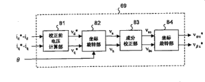
The motor control system shown in fig. 14 includes a motor 1, an inverter 2, a dc power supply 4, and a current sensor 5, and further includes respective portions referred to by reference numerals 21 to 30. In embodiment 1, the control unit 3 shown in fig. 1 is formed by the parts referred to by reference numerals 21 to 30.
As described aboveThe current sensor 5 detects a bus current and outputs a signal indicating a current value of the bus current. The current detection unit 21 refers to the three-phase voltage command value v output from the coordinate converter 30u *,vv *And vw *The time points ST1 and ST2 (see fig. 6) at which the output signal of the current sensor 5 is sampled are determined while specifying which phase is the maximum phase, the intermediate phase, and the minimum phase, and the U-phase current i is calculated and outputted from the current value of the bus current (the output signal value of the current sensor 5) obtained at this time points ST1 and ST2uAnd V phase current iv. In this case, if necessary, i is usedu+iv+IvA relation of 0.
V as explained with reference to FIG. 6u *,vv *And vw *Set values Cnt U, Cnt V, and Cnt W as counters, respectively. A current detection unit 21 according to vu *,vv *And vw *The magnitude relation of the set values Cnt U, Cnt V and Cnt W of the counters is determined, and the current time is designated to any of the 1 ST to 6 th modes, and the times ST1 and ST2 at which the bus current should be detected are determined in consideration of the designated mode. For example, when "Cnt U > Cnt V > Cnt W", it is determined that the current time belongs to the 1 ST mode, and a time corresponding to the set values Cnt W and Cnt V is defined as ST1, and a time corresponding to the set values Cnt V and Cnt U is defined as ST 2. When the present time belongs to the 1 ST mode, the bus currents detected at the times ST1 and ST2 are (-i), respectivelyw) And iu。
The coordinate converter 22 converts the three-phase current detected by the current detection unit 21 into a two-phase current on the α β coordinate. I.e. as the motor current IaI of the U-phase axis component and the V-phase axis component ofuAnd ivConverted as motor current IaI of the alpha-axis component and the beta-axis component of (1)αAnd iβ. I resulting from the transformationαAnd iβAnd supplied to the magnetic flux/torque estimator 23.
The α -axis component and the β -axis component of the interlinkage magnetic flux of the armature coils (7u, 7v, and 7w) in fig. 1 are referred to as α -axis magnetic Φ, respectivelyαAnd beta axis flux phiβ. The magnetic flux/torque estimator 23 estimates the magnetic flux from the α -axis current, the β -axis current, and the voltage command vector, as in the motor drive system of fig. 25, but uses the voltage command vector subjected to the correction processing as the voltage command vector used for the estimation. That is, the magnetic flux/torque estimator 23 estimates the magnetic flux/torque from i from the coordinate converter 22αAnd iβV from voltage command calculation unit 29αc *And vβc *Estimating the alpha-axis magnetic flux phiαAnd beta axis flux phiβ。vαc *And vβc *Respectively, each represents v which should follow the appearance in the above formula (1-5)αcAnd vβcThe target value of (2). v. ofαc *And vβc *The component of the coordinate axis forming the corrected voltage command vector on the α β coordinate is, but the meaning thereof will be more clearly understood by the explanation of the voltage command calculation unit 29 described later.
Specifically, the magnetic flux/torque estimator 23 estimates Φ from the following expressions (2-1) and (2-2)αAnd phiβ. Then, the magnetic flux/vector estimator 23 estimates Φ from the magnetic flux/vector itselfαAnd phiβCalculated from the following formula (2-3)αAnd phiβPhase theta of formed interlinkage magnetic flux vector with alpha axis as referenceSAnd the torque T generated by the motor 1 is estimated from the following expression (2-4). The right integrals of equations (2-1) and (2-2) are integrals over time t, and the integral interval is from time t, which is the reference time, to the current time, which is 0.
φα=∫(vαc *-Raiα)dt+φα|1=0 …(2-1)
φβ=∫(vβc *-Raiβ)dt+φβ|1=0 …(2-2)
θS=tan-1(φβ/φn) …(2-3)
T=PN(φαiβ-φβiα) …(2-4)
Wherein,
Rashowing the resistance value of each phase of the armature coils (7u, 7v and 7w),
PNthe number of pole pairs of the motor 1 is shown,
Φα|t=0and phiβ|t=0Phi each indicating that time t is 0αAnd phiβValue of (i.e., #)αAnd phiβInitial value of (1).
In addition, definitions of state quantities appearing in the following equations and the like are also made here.
Ld,LqD-axis inductance (d-axis component of armature coil inductance of the motor 1), q-axis inductance (q-axis component of armature coil inductance of the motor 1), ΦαWhich shows armature interlinkage magnetic flux generated by a permanent magnet provided on the rotor 6 of the motor 1.
idAnd iqRespectively expressed as motor voltage IaD-axis current and q-axis current of the d-axis component and the q-axis component of (1).
The d-axis is a shaft set to the N-pole direction of the permanent magnet of the rotor 6, and the q-axis is a shaft extending by pi/2 from the d-axis. The description of the d-axis and the q-axis is made by example 2 described later. And, Ra,Ld,Lq,Φa,PN,Φα|t=0And phiβ|t=0The design stage of the motor drive system is predetermined.
A subtractor 24 for calculating the torque T estimated by the flux/torque estimator 23 and a torque command value T representing a target value of the torque T*Torque error Δ T (T-T)*). In the direct torque control, the torque command value T is required*At the same time, a command value for the amplitude of the interlinkage magnetic flux is provided. From | ΦS *And | represents the instruction value for that amplitude. L ΦS *I is represented by phiαAnd phiβA target value of the magnitude of the formed interlinkage magnetic flux vector (i.e., the amplitude of the interlinkage magnetic flux). Usually, the amplitude of the interlinkage magnetic flux | ΦSI and the torque T are expressed by the following formulas (2-5) and (2-6). Therefore, for example, when the maximum torque control is to be realized, the expression | Φ is created by substituting the formula (2-7) for the formula (2-5) and the formula (2-6) for calculating the d-axis current for realizing the maximum torque controlSTabular data of the relationship of | and T. The table data is stored in the table 25 of fig. 14, and when | Φ isSProcessing | and T into | ΦS *I and T*Based on the torque command value T, using table 25*Calculating | ΦS *|。
T=PN(Φaiq-(Lq-Ld)idiq) …(2-6)
From Table 25, | ΦS *And is supplied to the magnetic flux command calculation unit 26. However, | Φ is calculated from the following expression (2-8) when weak magnetic flux control is required such as when the motor 1 rotates at high speedS *And supplies it to the magnetic flux command calculation unit 26. Where ω is an electrical angular velocity (electrical angular velocity of d-axis) in the rotation of the rotor 6 of the motor 1, VomMotor voltage V to be limited for control by weak magnetic fluxaThe limit value of (2).
Fig. 15 shows an internal block diagram of the magnetic flux command calculation unit 26. The magnetic flux command calculation unit 26 shown in fig. 15 includes the parts referred to by reference numerals 35 to 37. The magnetic flux command calculation unit 26 calculates the magnetic flux command from | Φ obtained as described aboveS *L, θ from the magnetic flux/torque estimator 23SAnd Δ T from the subtractor 24, calculates and outputs ΦαAnd phiβAlpha-axis magnetic flux command value phi as target value ofα *And a beta axis magnetic flux command value phiβ *。
Specifically, the PI control section 35 performs a PI control operation,proportional integral control is performed to converge Δ T to zero, and a phase correction amount Δ θ corresponding to Δ T is calculatedS *. Theta is calculated by adder 36SAnd Δ θS *Sum of (θ)S+ΔθS *). The sum is used as a phase command value thetaS *(=(θS+ΔθS *) Is supplied to the vector generation section 37. The vector generator 37 generates a vector from | ΦS *I and thetaS *Phi was calculated from the following formulas (2-9a) and (2-9b)α *And phiβ *。
φα *=|φS *|cosθS * …(2-9a)
φβ *=|φS *|sinθS * …(2-9b)
Φ calculated by the magnetic flux command calculation unit 26α *And phiβ *And phi estimated by the magnetic flux/torque estimator 23αAnd phiβAnd supplied to subtractors 27 and 28. Subtractors 27 and 28 calculate the deviation (phi)α *-Φα) And (phi)β *-Φβ) And supplied to the voltage command calculation unit 29. In addition, i is obtained by the coordinate converter 22αAnd iβAre supplied to the voltage command calculation unit 29 (the appearance thereof is omitted in fig. 14).
Fig. 16 shows an internal block diagram of the voltage command calculation unit 29. The voltage command calculation unit 29 in fig. 16 includes the respective portions referenced by reference numerals 41 to 44. A pre-correction voltage calculation unit 41 based on (phi)α *-Φα),(Φβ *-Φβ),iαAnd iβCalculating the alpha-axis voltage command value vα *And a beta axis voltage command value vβ *So that phi isαFollow phiα *And phiβFollow phiβ *。vα *And vβ *Are respectively used for mixingα *-Φα) And (phi)β *-Φβ) V co-converging to zeroαAnd vβThe target value of (2). Calculating vα *And vβ *(see the following formula (2-10)) so as to be represented by vα *And vβ *Formed voltage command vector (v)αβ *) Becomes from phiαAnd phiβFormed interlinkage magnetic flux vector (phi)αβ) Is differentiated in time byαAnd iβFormed current vector (i)αβ) And RaThe sum of the resulting voltage drop vectors. The calculation method is further embodied by taking into account the values generated in the discretized motor drive system. The description of the embodied algorithm is provided later.
A coordinate rotation unit 42 for rotating v according to the above formula (1-2)α *And vβ *Is transformed into vaAnd vb. I.e. will be defined by vα *And vβ *The voltage command vector of 2 phases on the alpha-beta coordinate is converted into a vector of vaAnd vbThe voltage command vectors of 2 phases on the ab coordinates shown (these voltage command vectors correspond to the voltage vector 110 in fig. 8). The value of n used for the calculation of the formula (1-2) is calculated by the above formula (1-1a) or (1-1 b). The n value calculated by the coordinate rotation unit 42 is also used for calculation by the coordinate rotation unit 44. V is used for the coordinate rotation unit 42α *And vβ *V as the respective right sides of formulae (1-1a), (1-1b) and (1-2)αAnd vβ。
A composition correction unit 43 for vaAnd vbThe correction processing of step S2 in fig. 10 is performed to correct vaAnd vbRespectively as vacAnd vbcAnd (6) outputting. However, when no correction is necessary, v is changed toac=vaAnd v isbc=vb。
The coordinate rotation part 44 corrects the corrected a-axis voltage v according to the above equation (1-5)acAnd b-axis voltage vbcConverted into corrected alpha-axis voltage vαcAnd b-axis voltage vβcV to be obtainedαcAnd vβcRespectively as vαc *And vβc *And (6) outputting. I.e. will be defined by vacAnd vbcThe corrected 2-phase voltage command vector on the ab coordinate is converted into a voltage command vector of vαc *And vβc *The voltage command vector of 2 phases on the corrected α β coordinate is shown. v. ofαc *And vβc *Respectively representing the α -axis component and the β -axis component of the corrected voltage command vector.
V calculated by voltage command calculation unit 29 (coordinate rotation unit 44)αc *And vβc *Is supplied to the coordinate transformer 30 of fig. 14. A coordinate converter 30 for converting vαc *And vβc *Is converted intou *,vv *And vw *The three-phase voltage command values thus constituted are output to the inverter 2. And an inverter 2 for supplying a three-phase ac current to the motor 1 based on the three-phase voltage command value. V calculated by coordinate converter 30u *、vv *And vw *Is equivalent to the sum of vαc *And vβc *The U-phase axis component, the V-phase axis component, and the W-phase axis component of the voltage command vector are shown.
(calculation formula of discretization)
The calculation in the motor drive system is performed based on the discretized instantaneous values of the respective state quantities. Here, when the input values and the output values of the respective portions referred to by the symbols 21 to 30 are discretized by the discretization period Ts, descriptions about these operations are added.
Now, consider a case where the reference time t is 0, which belongs to the 0 th cycle, and the current time belongs to the m-th cycle (m is a natural number). And are respectively composed of iu[m]And iv[m]Denotes i in the m-th cycleuAnd ivRespectively consisting of iα[m]And iβ[m]Representation is based on iu[m]And iv[m]I of (a)αAnd iβ. And, by vαc *[m]And vβc *[m]Respectively indicate v outputted from voltage command calculation unit 29 in the m-th cycleαc *And vβc *From phiα[m]And phiβ[m]And thetaS[m]And T [ m ]]Respectively represent based on iα[m]And iβ[m]And vαc *[m]And vβc *[m]Phi ofαAnd phiβAnd thetaSAnd T. And then from T*[m]Denotes T in the m-th cycle*From | ΦS *|[m]Representation is based on T*[m]Of (a) | ΦS *L. In addition, from Δ T [ m ]]Representation is based on T*[m]And T [ m ]]Δ T of (a).
At this time, the magnetic flux/torque estimator 23 calculates Φ from the following expressions (3-1) to (3-4) corresponding to the above expressions (2-1) to (2-4)α[m]And phiβ[m]And thetaS[m]And T [ m ]]。
θS[m]=tan-1(φβ[m]/φα[m]) …(3-3)
T[m]=PN(φα[m]iβ[m]-φβ[m]iα[m]) …(3-4)
The magnetic flux command calculation unit 26 calculates the magnetic flux command based on Δ T [ m ]]、θS[m]And | ΦS *|[m]Calculating phiα *[m+1]And phiβ *[m+1]Subtractors 27 and 28 calculate the deviation (phi)α *[m+1]-Φα[m]) And (phi)β *[m+1]-Φβ[m]). I.e. according to Δ T, θ in the m-th cycleSAnd | ΦS *I determine phi of the next cycleαAnd phiβAnd a deviation between the target value and the instantaneous value of the interlinkage magnetic flux at the present time is obtained.
The pre-correction voltage calculation unit 41 (see fig. 16) in the voltage command calculation unit 29 is configured to control Φ in the (m +1) th cycleαAnd phiβAnd phiα *[m+1]And phiβ *[m+1]And the required voltage command vector is calculated. That is, the pre-correction voltage calculation unit 41 calculates v from the following expression (3-5) corresponding to the above expression (2-10)α *[m+1]And vβ *[m+1]. Then, the voltage command calculation part 29 calculates the voltage command according to vα *[m+1]And vβ *[m+1]By the correction processing, v representing the voltage to be applied to the motor 1 in the (m +1) th cycle is calculatedαc *[m+1]And vβc *[m+1]These are supplied to the inverter 2 by coordinate conversion by the coordinate converter 30.
The equation (3-5) (and the equation (2-10) above) is derived from a difference equation representing the relationship between the interlinkage magnetic flux and the voltage corresponding to fig. 17. Also, in FIG. 17,. phi.αβ[m+1]Means from Φα[m]And phiβ[m]Formed vector of phiαβ *[m+1]Means from Φα *[m+1]And phiβ *[m+1]The formed vector.
As described above, in the present embodiment, the motor current can be reliably detected by the step of providing the correction voltage vector (voltage command vector). Further, by performing the correction processing on ab coordinates where correction is easy to be performed, necessary correction is simply and reliably realized. In the ab coordinate, the coordinate axis component v of the voltage vector (voltage command vector) is corrected independentlyaAnd vbIt is possible, therefore, to simply correct the contents. In particular, when the applied voltage is low, all 3 phases need to be corrected, but in such a case, the correction amount can be easily determined.
Further, by performing direct torque control, torque ripple can be reduced even when a motor having a higher harmonic in the magnet flux or inductance distribution is used. In addition, as the motor 1, a synchronous reluctance motor or an induction motor may be used in addition to the embedded magnet type motor. In the synchronous reluctance motor or the -core motor, since a higher harmonic exists in the magnet flux or the inductance distribution, the effect of reducing the torque ripple can be obtained by the direct torque control.
In the present embodiment, the voltage command value is corrected in order to reliably detect the motor current. Although an estimation error occurs if the magnetic flux is estimated using the voltage command value before correction, in the present embodiment, the voltage command value (v) after correction is usedαc *And vβc *) Since the magnetic flux is estimated, no estimation error is generated by the correction. Further, since the correction processing is performed at the voltage vector stage, the corrected voltage command vector for magnetic flux estimation can be easily obtained, the step of inverse-converting the three-phase voltages is not required, and the voltage detection ticket for detecting the three-phase voltages which is necessary in the motor drive system of fig. 25 is also not required.
(embodiment 2)
Next, embodiment 2 will be explained. The symbols and the like defined in embodiment 1 are also common in embodiment 2. Fig. 18 is a block diagram showing a motor drive system according to embodiment 2. In the motor drive system of fig. 18, vector control is executed by calculating the rotor position from the estimated value of the interlinkage magnetic flux.
Before explaining the respective parts in fig. 18, the axes defined in embodiment 2 and the operational expressions relating to the operations in embodiment 2 are explained. Refer to fig. 19. Fig. 19 is an analysis model diagram of the motor 1. Fig. 19 shows a U-phase axis, a V-phase axis, and a W-phase axis. 6a is such a permanent magnet provided in the rotor 6 of the motor 1. In a rotating coordinate system that rotates at the same speed as the magnetic flux generated by the permanent magnet 6a, the direction of the magnetic flux generated by the permanent magnet 6a is defined as the d-axis. Although not shown in the figure, a phase advancing by 90 degrees from the d-axis is taken as the q-axis. The d-axis and the q-axis are coordinate axes of the rotational coordinate system, and these coordinate axes are referred to as d q coordinates.
The d-axis (and q-axis) rotates, and the rotational speed (electrical angular velocity) thereof is represented by ω. Further, θ represents a phase of the d-axis in the counterclockwise direction as viewed from the armature coil fixing axis of the U-phase. Counterclockwise, in line with the phase advance direction. Since the phase θ is generally referred to as a rotor position, it is hereinafter referred to as a rotor position.
Respectively by d-axis voltage vdAnd q-axis voltage vqRepresenting the overall motor voltage V applied by the inverter 2 to the motor 1aD-axis component and q-axis component of (1). In addition, in embodiment 1, it is described that d-axis currents i are respectively supplieddAnd q-axis current iqShows the overall motor current I supplied by the inverter 2 to the motor 1aD-axis component and q-axis component of (1).
Respectively by d-axis voltage command values vd *And q-axis voltage command value vq *Representing the voltage v to the d-axisdAnd q-axis voltage vqThe instruction value of (2). v. ofd *And vq *Respectively represent vdAnd vqThe voltage that should be tracked (target voltage value).
Respectively controlled by d-axis current command value id *And q-axis current command value iq *Represents the current i to the d-axisdAnd q-axis current iqThe instruction value of (2). i.e. id *And iq *Respectively represent idAnd iqCurrent that should be tracked (target current value).
The extended induced voltage equation on dq coordinates is expressed by equation (4-1), extended induced voltage EexRepresented by formula (4-2). In the following expression, p is a differential operator. When the formula (4-1) is rewritten focusing on the α β coordinate, the formula (4-3) is obtained. Further, the expression (4-3) is established, and is also shown in "4 names of others in city," extension induction voltage モデルに base づく super active permanent Magnet Synchronous モ - タ peripheral センサレス (sensory control of salt-poler magnetic particles Using Extended electric forms) ", and" profile electronics D, 2002, vol.122, No.12, p.1088-1096 ".
Eex=ω((Ld-Lq)id+Φα)-(Ld-Lq)(piq) …(4-2)
After shifting the determinant of the 1 st term on the right of equation (4-3) to the left, if integration is performed on both sides by time, equations (4-4) and (4-5) can be obtained (since θ ═ ω t, if integration-sin θ becomes cos θ/ω, if integration cos θ becomes sin θ/ω, sin θ/ω). However, the extended induced voltage E is ignored at this timeexI of (a)qThe derivative term (i.e., the 2 nd term on the right side of equation (4-2)).
∫(vα-Raiα-ω(Ld-Lq)iβ)dt-Ldiα=((Ld-Lq)id+Φa)cosθ=φexα
…(4-4)
∫(vβ+ω(Ld-Lq)iα-Raiβ)dt-Ldiβ=((Ld-Lq)id+Φa)sinθ=φexβ
…(4-5)
If set to "Eex=Φexω ", then EexIndicating the interlinkage magnetic flux phi of the armature coil of the motor 1exAnd induced voltage generated by rotation of the rotor 6. If capturing EexAs an induced voltage vector in the rotating coordinate system, the induced voltage vector becomes a vector on the q-axis. Also, if capturing ΦexWhen the interlinkage magnetic flux vector in the rotating coordinate system is taken, the interlinkage magnetic flux vector becomes a vector on the d axis. Phi also appearing in the formulae (4-4) and (4-5)exαAnd phiexβRespectively represents phiexAnd an alpha axis component and a beta axis component of (c).
Interlinkage magnetic flux vector phi with alpha axis as referenceexPhase of (a)exRepresented by the following formula (4-6). In the motor drive system according to embodiment 2, the interlinkage magnetic flux vector Φ is estimatedexAlpha axis component of (phi)exαAnd beta axis component phiexβThe phase theta is estimated from the estimated valueex. As described above, the flux vector Φ due to the linkageexShould become a vector on the d-axis, so estimated θexIdeally in accordance with theta. Here, θ is estimated fromexAnd a difference (axis error) between θ used for coordinate transformation, and by performing pll (phase Locked loop) control, the rotational speed and the rotor position are estimated. The rotation speed ω and the rotor position θ are estimated from the following equations (4-7) and (4-8). Wherein, KpAnd KiThe coefficients are a proportional coefficient and an integral coefficient in proportional-integral control, and S is a laplacian operator.
θex=tan-1(φexβ/φexα) …(4-6)
ω=(Kp+Ki/s)(θex-θ) …(4-7)
θ=ω/s …(4-8)
A specific operation of the motor drive system of fig. 18 will be described. The motor control system of fig. 18 includes: a motor 1; an inverter 2; the DC power supply 4 and the current sensor 5 are provided with parts referenced by reference numerals 61-70. In embodiment 2, the control unit 3 shown in FIG. 1 is formed by the parts referred to by reference numerals 61 to 70.
As described above, the current sensor 5 detects the bus current and outputs a signal indicating the current value of the bus current. The current detection unit 61 and the coordinate converter 62 are the same as the current detection unit 21 and the coordinate converter 22 in fig. 14. That is, the current detection unit 61 detects the output signal value of the current sensor 5 and the three-phase voltage command value vu *、vv *And vw *Like the current detection unit 21 of fig. 14, the U-phase current i is calculated and outputuAnd V phase current iv. However, the three-phase voltage command value v for the current detection unit 61u *、vv *And vw *Supplied from the coordinate converter 70. A coordinate converter 62 for converting i calculated by the current detection unit 61uAnd ivIs transformed into iαAnd iβ。
The magnetic flux estimator 63 estimates the magnetic flux from i obtained by the coordinate converter 62αAnd iβAnd v from voltage command calculation unit 69αc *And vβc *The interlinkage magnetic flux of the motor 1 is estimated (i.e., the interlinkage magnetic flux Φ is calculated) from the above expressions (4-4) and (4-5)exAlpha axis component of (phi)exαAnd beta axis component phiexβ). At this time, v is usedac *And vβc *As v in formulae (4-4) and (4-5)αAnd vβ. In addition, ω estimated by the position/velocity estimator 64 may also be used.
Fig. 20 shows an internal block diagram of the position/velocity estimator 64. The position/velocity estimator 64 shown in FIG. 20 includes respective portions referred to by reference numerals 75 to 78. ThetaexA calculation unit 75 for calculating from the phi calculated by the magnetic flux estimator 63exαAnd phiexβThe phase θ is calculated from the above equation (4-6)ex. A subtractor 76, derived from the equationexθ output from the calculation unit 75exThe axis error (theta) is calculated by subtracting theta from the output of the integrator 78ex- θ). PI control part 77 for making the axis error (theta)ex- θ) proportional integral control converging to zero. That is, the rotational speed ω is calculated by performing the calculation according to the above expression (4-7). The integrator 78 calculates the rotational position θ by integrating ω calculated by the PI control unit 77 based on the above expression (4-8). ω and θ calculated by the PI control unit 77 and the integrator 78 are used as the selected speed and the rotor position estimated by the position/speed estimator 64.
The α β/dq converter 65 converts i obtained by the coordinate converter 62 based on θ estimated by the position/velocity estimator 64αAnd iβConverted to i as a component of current on dq coordinatesdAnd iq。
The current command calculation unit 66 generates and outputs a d-axis current command value id *And q-axis current command value iq *. For example, generate iq *So that the rotational speed ω follows the externally supplied speed command value ω*If necessary, refer to iq *Etc. while generating id *To achieve the desired vector control (e.g., maximum vector control).
Subtractors 67 and 68, based on i from the α β/dq converter 65dAnd iqAnd i from the current command calculation section 66d *And iq *Calculating the current error (i)d *-id) And (i)q *-iq) And supplies the calculation result to the voltage command calculation unit 69.
Fig. 21 shows an internal block diagram of the voltage command calculation unit 69. The voltage command calculation unit 69 shown in fig. 21 includes parts referred to by reference numerals 81 to 84. The pre-correction voltage calculation unit 81 calculates a d-axis voltage command value v by proportional-integral controld *And q-axis voltage command value vq *So as to make the current error (i)d *-id) And (i)q *-iq) Converging to zero. v. ofd *And vq *Is used for mixing (i)d *-id) And (i)q *-iq) Convergence to zero v simultaneouslydAnd vqThe target value of (2).
The coordinate rotation part 82 rotates v based on θ estimated by the position/velocity estimator 64d *And vq *Is transformed into vaAnd vb. Referring to fig. 22, a description of the conversion method will be added. Fig. 22 is a spatial vector diagram showing the relationship among the U-phase axis, the V-phase axis, the W-phase axis, the d-axis, the q-axis, and the voltage vector 110. The phase of the voltage vector 110 as seen from the q-axis is denoted by epsilon. The phase of the voltage vector 110 with reference to the U-phase axis is represented by (θ + ε + π/2). In addition, a1Shaft-a6Of the axes (see fig. 9), the phase of the axis closest to the voltage vector 110 is represented by "(n' +2) pi/3" with reference to the U-phase axis. Where n' is the quotient of (θ + ε) divided by π/3.
For convenience, as shown in fig. 22, θ is decomposed into the above-described phase (n '+ 2) pi/3, and a differential phase θ between its phase (n' +2) pi/3 and θD. These phase relationships are represented by the following formula (5-1). Thus, v represents the voltage component at d q coordinatesdAnd vqCan be converted into v representing a voltage component on ab coordinates by the following formula (5-2)aAnd vb. In addition,. epsilon.is represented by the following formula (5-3).
The coordinate rotating section 82 rotates v according to the above equations (5-1) to (5-3)d *And vq *Is transformed into vaAnd vb. However, in this case, v is usedd *And vq *As v in formulae (5-2) and (5-3)dAnd vq. Specifically, n 'is obtained from epsilon obtained by expression (5-3) and estimated theta, and theta is obtained by substituting theta and n' obtained by expression (5-1) with thetaD. Then, the obtained θ is usedDV is a reaction product of the formula (5-2)d *And vq *Is transformed into vaAnd vb. However, the equation "n '+ 2 ═ n" holds between n' and n (see fig. 8) described in embodiment 1. The value obtained by adding 2 to n' obtained by the coordinate rotation unit 82 (i.e., n) is used for the calculation by the coordinate rotation unit 84.
V obtained by the coordinate rotation unit 82aAnd vbIs sent to the composition correcting section 83. The component correcting section 83 and the coordinate rotating section 84 are the same as the component correcting section 43 and the coordinate rotating section 44 in fig. 16. Namely, the component correcting section 83, for vaAnd vbThe correction processing in step S2 of FIG. 10 is performed to correct vaAnd vbEach as vacAnd vbcAnd (6) outputting. However, when no correction is required, vac=vaAnd v isbc=vb。
The coordinate rotation unit 84 corrects the corrected a-axis voltage v according to the above equation (1-5)acAnd b-axis voltage vbcConverted into corrected alpha-axis voltage vαcAnd beta axis voltage vβC. V to be obtainedacAnd vbcRespectively as vαc *And vβc *And (6) outputting.
V calculated by the voltage command calculation unit 69 (coordinate rotation unit 84)αc *And vβc *And supplied to the coordinate converter 70 of fig. 18. A coordinate converter 70 for converting vαc *And vβc *Is converted to be composed of vu *,vv *And vw *The three-phase voltage command values thus constituted are output to the inverter 2. The inverter 2 supplies a three-phase ac current to the motor 1 based on the three-phase voltage command value.
In this embodiment, since the step of correcting the voltage vector (voltage command vector) is also provided, the motor current can be reliably detected. Further, by executing the correction process on ab coordinates where the correction process is easy to be performed, necessary correction can be easily and reliably realized. In the ab coordinate, the component v of the coordinate axis of the voltage vector (voltage command vector) is corrected independentlyaAnd vbThat is, the correction contents are simple. Particularly, when the applied voltage is low, all 3 phases need to be corrected, but in such a case, the correction amount can be easily determined.
In the present embodiment, correction is applied to the voltage command value in order to reliably detect the motor current. Although an estimation error occurs if the magnetic flux is estimated using the voltage command value before correction, in the present embodiment, the voltage command value (v) after correction is usedαc *And vβc *) Since the magnetic flux is estimated, no estimation error due to correction occurs. Further, since the correction processing is performed at the voltage vector stage, the corrected voltage command vector for magnetic flux estimation can be easily obtained, and a step of inverse-converting the three-phase voltages is not necessary, and a voltage detector for detecting the three-phase voltages, which is necessary in the motor drive system of fig. 25, is also not necessary.
The embodiment of the motor drive system to which the present invention is applied has been described above, but the present invention includes various modifications (or other embodiments). Hereinafter, comments 1 to 5 are recorded as modifications (or other embodiments) or comment items. The contents described in the respective comments may be arbitrarily combined as long as they are not contradictory.
(Note 1)
The case of using 3-phase modulation by the inverter 2 is dealt with, but the present invention does not depend on the modulation method. For example, when 2-phase modulation is performed by the inverter 2, the energization pattern is different from the case of 3-phase modulation shown in fig. 3. In the 2-phase modulation, since the lower arm of the minimum phase is always on, the energization patterns corresponding to the time T0-T1 and the time T6-T7 in fig. 4 do not exist. However, as a result, if the bus current is detected by the energization patterns corresponding to the time intervals between T1 and T2 and between T2 and T3, the currents capable of detecting the maximum phase and the minimum phase are not changed.
(Note 2)
The motor drive system according to the present embodiment includes the various command values (Φ) described aboveα *,vd *Etc.) or other state quantities (phi)α,ΦexαEtc.) are arbitrary. That is, for example, the control unit 3 (seeThese are derived by the calculation in fig. 1), and may be derived from table data set in advance.
(Note 3)
A part or all of the functions of the control unit 3 (see fig. 1) are realized by software (program) installed in, for example, a general-purpose microcomputer or the like. When the control unit 3 is implemented by software, a block diagram showing the configuration of each part of the control unit 3 is changed to a functional block diagram. Of course, the control unit 3 may be configured by hardware alone, instead of software (program).
(Note 4)
For example, the following can be considered. The control unit 3 functions as a motor control device. The motor control device may include the current sensor 5 shown in fig. 1 and the like. The motor current detection means for detecting the motor current based on the output signal of the current sensor 5 includes the current detection unit 21 shown in fig. 14 or the current detection unit 61 shown in fig. 18. For example, the pre-correction voltage calculation unit 41 and the coordinate rotation unit 42 in fig. 16, or the pre-correction voltage calculation unit 81 and the coordinate rotation unit 82 in fig. 21 function as voltage command vector generation means. For example, the component correcting unit 43 in fig. 16 or the component correcting unit 83 in fig. 21 functions as a voltage command vector correcting means.
(Note 5)
In the present specification, for the sake of simplicity of description, only the symbol (i) is usedαEtc.) and a state quantity (state variable) corresponding to the symbol may be expressed. That is, in the present specification, for example, "iα"and" α axis current iα"refers to the same amount.
The present invention is applicable to all electric machines using an electric motor. The air conditioner is particularly suitable for compressors for refrigerators, vehicle-mounted air conditioners, electric vehicles and the like.
Claims (9)
1. A motor control device is characterized by comprising:
a motor current detection means for detecting a motor current flowing through the motor based on a current flowing between an inverter for driving the three-phase motor and a dc power supply;
a voltage command vector generating means for generating a voltage command vector indicating a vector of a voltage to be followed by an applied voltage to the motor, based on a linkage magnetic flux of an armature coil of the motor;
a voltage command vector correction unit that corrects the generated voltage command vector; and
a magnetic flux estimating means for estimating the linkage magnetic flux from the motor current and the corrected voltage command vector,
and controlling the motor by the inverter based on the corrected voltage command vector.
2. The motor control device according to claim 1,
the voltage command vector generated by the voltage command vector generation means is a voltage command vector on a rotation coordinate,
the voltage command vector correction means corrects the voltage command vector on the rotation coordinate in the process of converting the voltage command vector on the rotation coordinate into three-phase voltage command values on a three-phase fixed coordinate,
the motor control device controls the motor by supplying the three-phase voltage command values corresponding to the corrected voltage command vector to the inverter.
3. The motor control device according to claim 1,
the voltage command vector generated by the voltage command vector generation means is a two-phase voltage command vector on a b coordinates that rotates stepwise at an electrical angle of 60 degrees in accordance with the phase of the voltage command vector with respect to a predetermined fixed axis.
4. The motor control device of claim 3. It is characterized in that the preparation method is characterized in that,
the voltage command vector correction means determines whether or not correction is necessary based on the magnitude of a coordinate axis component forming the two-phase voltage command vector at the ab coordinate, and corrects the two-phase voltage command vector at the ab coordinate by correcting the coordinate axis component when correction is necessary.
5. The motor control device according to claim 3,
further comprising coordinate conversion means for converting the two-phase voltage command vector on the ab coordinate corrected by the voltage command vector correction means into a voltage command vector on an α β coordinate having fixed α and β axes as coordinate axes,
the magnetic flux estimating means estimates the interlinkage magnetic flux from the motor current and the voltage command vector on the α β coordinate.
6. The motor control device according to claim 3,
further comprising coordinate conversion means for converting the two-phase voltage command vector on the ab coordinate corrected by the voltage command vector correction means into a voltage command vector on an α β coordinate having fixed α and β axes as coordinate axes,
the magnetic flux estimating means estimates a coordinate axis component on the α β coordinate of the interlinkage magnetic flux from a coordinate axis component on the α β coordinate of the motor current and a voltage command vector on the α β coordinate.
7. The motor control device according to claim 1,
further comprising a torque estimating means for estimating a torque generated by the motor based on the motor current and the estimated linkage flux,
and performing direct torque control on the motor based on the estimated torque.
8. The motor control device according to claim 1,
further comprises a rotor position estimating means for estimating a rotor position of the motor based on the estimated interlinkage magnetic flux,
and performing vector control on the motor based on the estimated rotor position.
9. A motor drive system is characterized by comprising:
a three-phase motor;
an inverter for driving the motor; and
the motor control device according to claim 1, wherein the inverter is controlled to control the motor.
Applications Claiming Priority (3)
| Application Number | Priority Date | Filing Date | Title |
|---|---|---|---|
| JP2007195544 | 2007-07-27 | ||
| JP2007195544A JP4961292B2 (en) | 2007-07-27 | 2007-07-27 | Motor control device |
| JP2007-195544 | 2007-07-27 |
Publications (2)
| Publication Number | Publication Date |
|---|---|
| CN101355338A CN101355338A (en) | 2009-01-28 |
| CN101355338B true CN101355338B (en) | 2011-03-16 |
Family
ID=40139151
Family Applications (1)
| Application Number | Title | Priority Date | Filing Date |
|---|---|---|---|
| CN2008101443020A Expired - Fee Related CN101355338B (en) | 2007-07-27 | 2008-07-25 | Motor control device |
Country Status (4)
| Country | Link |
|---|---|
| US (1) | US7898197B2 (en) |
| EP (1) | EP2026460B1 (en) |
| JP (1) | JP4961292B2 (en) |
| CN (1) | CN101355338B (en) |
Families Citing this family (44)
| Publication number | Priority date | Publication date | Assignee | Title |
|---|---|---|---|---|
| US7629761B2 (en) * | 2007-07-13 | 2009-12-08 | Xerox Corporation | System for measuring current in multiple motor coils using a single sensing element |
| JP5453729B2 (en) * | 2008-04-14 | 2014-03-26 | 株式会社ジェイテクト | Motor control device and electric power steering device |
| ITPD20090140A1 (en) * | 2009-05-15 | 2010-11-16 | Reel S R L Unipersonale | REFRIGERANT GROUP |
| EP2437391B1 (en) * | 2009-05-27 | 2020-11-11 | Mitsubishi Electric Corporation | Device for estimating magnetic pole position in synchronous motor |
| JP2011004506A (en) * | 2009-06-18 | 2011-01-06 | Sanyo Electric Co Ltd | Motor control device |
| US8264192B2 (en) | 2009-08-10 | 2012-09-11 | Emerson Climate Technologies, Inc. | Controller and method for transitioning between control angles |
| US8698433B2 (en) * | 2009-08-10 | 2014-04-15 | Emerson Climate Technologies, Inc. | Controller and method for minimizing phase advance current |
| US8508166B2 (en) | 2009-08-10 | 2013-08-13 | Emerson Climate Technologies, Inc. | Power factor correction with variable bus voltage |
| JP2011050178A (en) * | 2009-08-27 | 2011-03-10 | Sanyo Electric Co Ltd | Motor control device and generator control device |
| JP4912516B2 (en) * | 2009-12-08 | 2012-04-11 | 三菱電機株式会社 | Power converter |
| JP5454685B2 (en) * | 2010-06-25 | 2014-03-26 | トヨタ自動車株式会社 | Motor drive device and vehicle equipped with the same |
| JP5691272B2 (en) * | 2010-07-13 | 2015-04-01 | 日産自動車株式会社 | Power conversion system |
| JP5194083B2 (en) * | 2010-09-22 | 2013-05-08 | 山洋電気株式会社 | Method and apparatus for determining deterioration of permanent magnet of electrical equipment |
| EP2657667B1 (en) * | 2010-12-24 | 2016-03-30 | Toyota Jidosha Kabushiki Kaisha | Torque detection device |
| ES2811755T3 (en) * | 2011-05-13 | 2021-03-15 | Hitachi Ltd | Synchronous motor drive system |
| CN102320252B (en) * | 2011-06-27 | 2016-01-27 | 杭州阔博科技有限公司 | Control method of electric bicycle |
| US8860342B2 (en) | 2011-09-15 | 2014-10-14 | Curtiss-Wright Electro-Mechanical Corporation | System and method for controlling a permanent magnet motor |
| JP5416183B2 (en) * | 2011-09-30 | 2014-02-12 | 東芝シュネデール・インバータ株式会社 | Control device for permanent magnet synchronous motor |
| CN102497078B (en) * | 2011-12-02 | 2013-09-25 | 刘贵平 | Permanent magnet direct current motor |
| KR101534546B1 (en) * | 2012-01-11 | 2015-07-07 | 니혼 덴산 가부시키가이샤 | Motor controller |
| CN102832874B (en) * | 2012-02-24 | 2014-12-31 | 株洲南车时代电气股份有限公司 | System and method for controlling motor |
| US9634593B2 (en) | 2012-04-26 | 2017-04-25 | Emerson Climate Technologies, Inc. | System and method for permanent magnet motor control |
| GB2503039B (en) * | 2012-06-15 | 2020-05-27 | Danfoss Drives As | Method for controlling a synchronous reluctance electric motor |
| GB2503040B (en) * | 2012-06-15 | 2020-05-06 | Danfoss Drives As | Variable torque angle for electric motor |
| US9240749B2 (en) | 2012-08-10 | 2016-01-19 | Emerson Climate Technologies, Inc. | Motor drive control using pulse-width modulation pulse skipping |
| WO2014033959A1 (en) * | 2012-09-03 | 2014-03-06 | 東芝三菱電機産業システム株式会社 | Drive device for synchronous electric motor |
| JP5757304B2 (en) * | 2012-11-01 | 2015-07-29 | 株式会社デンソー | AC motor control device |
| DE112013005863T5 (en) * | 2012-12-06 | 2015-08-20 | Nidec Corporation | motor control |
| GB201301259D0 (en) * | 2013-01-24 | 2013-03-06 | Rolls Royce Plc | Method of controlling an ac machine and controller for controlling an ac machine |
| JP6166601B2 (en) * | 2013-07-02 | 2017-07-19 | パナソニック株式会社 | Motor control device and generator control device |
| JP6206767B2 (en) * | 2013-12-25 | 2017-10-04 | パナソニックIpマネジメント株式会社 | Motor control device and generator control device |
| KR102286371B1 (en) * | 2014-06-19 | 2021-08-05 | 현대모비스 주식회사 | Apparatus and Method for controlling temperature changes in a motor |
| JP6451984B2 (en) * | 2014-12-26 | 2019-01-16 | 日本電産株式会社 | Motor controller |
| JP6418093B2 (en) * | 2015-07-16 | 2018-11-07 | 株式会社デンソー | Power converter |
| CN105141200B (en) * | 2015-08-04 | 2019-04-09 | 矽力杰半导体技术(杭州)有限公司 | A kind of driving circuit and driving method of permanent magnet synchronous motor |
| US9774287B1 (en) * | 2016-07-14 | 2017-09-26 | GM Global Technology Operations LLC | Modification of stator current for enhanced flux weakening |
| CN107404271B (en) * | 2017-08-21 | 2019-11-26 | 西安交通大学 | A kind of non-synchronous motor parameter online recognition system and method |
| US10218301B1 (en) * | 2018-01-09 | 2019-02-26 | Mitsubishi Electric Research Laboratories, Inc. | System and method for speed sensorless motor drives |
| CN110752802B (en) * | 2018-03-30 | 2023-01-13 | 江苏美的清洁电器股份有限公司 | Rotor positioning method, positioning device and control system of brushless direct current motor |
| US10727770B2 (en) * | 2018-09-27 | 2020-07-28 | Tmeic Corporation | Control device for power conversion device, and motor drive system |
| JP7349321B2 (en) * | 2019-10-29 | 2023-09-22 | シナノケンシ株式会社 | Motor field position detection method |
| US11165381B2 (en) * | 2019-11-27 | 2021-11-02 | Infineon Technologies Austria Ag | Speed contant control and power constant control of a permanent magnet synchronous motor |
| JP7362523B2 (en) * | 2020-03-17 | 2023-10-17 | 日立Astemo株式会社 | Synchronous machine control device, synchronous machine control method, and electric vehicle |
| CN114257134B (en) * | 2021-12-07 | 2023-08-22 | 江苏大学 | Direct torque control method for harmonic suppression of double three-phase synchronous reluctance motor |
Citations (1)
| Publication number | Priority date | Publication date | Assignee | Title |
|---|---|---|---|---|
| CN1481604A (en) * | 2000-12-18 | 2004-03-10 | ��ʽ���簲����� | Method for correcting estimate of speed of induction motor and its device |
Family Cites Families (22)
| Publication number | Priority date | Publication date | Assignee | Title |
|---|---|---|---|---|
| JP2712470B2 (en) * | 1989-01-23 | 1998-02-10 | 松下電器産業株式会社 | Inverter current detection device |
| FR2665589B1 (en) * | 1990-08-01 | 1992-10-09 | Alsthom Gec | METHOD AND DEVICE FOR ESTIMATING MAGNETIC INDUCTION FLOWS FROM AN ASYNCHRONOUS MOTOR, IN PARTICULAR WITH A VIEW TO CONTROLLING THE MOTOR BY FLOW REGULATION. |
| US5481168A (en) * | 1993-01-29 | 1996-01-02 | Hitachi, Ltd. | Electric vehicle torque controller |
| JPH10108500A (en) * | 1996-09-27 | 1998-04-24 | Railway Technical Res Inst | Controller for ac three-phase motor |
| KR19990086188A (en) * | 1998-05-26 | 1999-12-15 | 윤종용 | Estimation of stator and rotor resistance values in induction motors |
| JP3710621B2 (en) * | 1998-05-29 | 2005-10-26 | 三菱電機株式会社 | Induction motor control device |
| KR100312771B1 (en) * | 1998-12-15 | 2002-05-09 | 장병우 | Driving control apparatus and method in power failure for elevator |
| JP3485844B2 (en) * | 1999-09-10 | 2004-01-13 | 勲 高橋 | Motor control device |
| JP4245777B2 (en) * | 2000-05-25 | 2009-04-02 | 三菱電機株式会社 | Control device and control method for induction motor |
| KR100371369B1 (en) * | 2000-08-18 | 2003-02-06 | 엘지산전 주식회사 | Vector control system of induction motor |
| KR100428505B1 (en) * | 2001-07-06 | 2004-04-28 | 삼성전자주식회사 | Method of speed speed and flux estimation for induction motor |
| JP3931079B2 (en) * | 2001-12-14 | 2007-06-13 | 松下電器産業株式会社 | Electric motor drive device and refrigeration device using the same |
| JP4370754B2 (en) * | 2002-04-02 | 2009-11-25 | 株式会社安川電機 | Sensorless control device and control method for AC motor |
| JP4059039B2 (en) * | 2002-08-30 | 2008-03-12 | 株式会社安川電機 | Control device for synchronous motor |
| US7075266B2 (en) | 2003-03-28 | 2006-07-11 | Hitachi, Ltd. | Apparatus for controlling an a. c. motor |
| JP4600726B2 (en) | 2004-03-18 | 2010-12-15 | 富士電機システムズ株式会社 | Three-phase inverter device |
| JP4672392B2 (en) | 2005-02-25 | 2011-04-20 | 株式会社東芝 | Inverter device |
| JP2007014114A (en) * | 2005-06-30 | 2007-01-18 | Matsushita Electric Ind Co Ltd | Pwm signal correcting means |
| JP4800861B2 (en) * | 2006-06-21 | 2011-10-26 | 三菱電機株式会社 | AC rotating machine control device |
| DE102006052042A1 (en) * | 2006-10-30 | 2008-05-15 | Bombardier Transportation Gmbh | Control and / or regulation of a 3-phase power converter for the operation of an asynchronous machine |
| JP5164025B2 (en) * | 2006-11-28 | 2013-03-13 | 株式会社安川電機 | Induction motor control device and control method thereof |
| KR101340527B1 (en) * | 2007-05-30 | 2013-12-11 | 엘지전자 주식회사 | Motor Driver System and Controlling Method for the Same |
-
2007
- 2007-07-27 JP JP2007195544A patent/JP4961292B2/en active Active
-
2008
- 2008-07-24 US US12/178,983 patent/US7898197B2/en not_active Expired - Fee Related
- 2008-07-24 EP EP08013379.6A patent/EP2026460B1/en active Active
- 2008-07-25 CN CN2008101443020A patent/CN101355338B/en not_active Expired - Fee Related
Patent Citations (1)
| Publication number | Priority date | Publication date | Assignee | Title |
|---|---|---|---|---|
| CN1481604A (en) * | 2000-12-18 | 2004-03-10 | ��ʽ���簲����� | Method for correcting estimate of speed of induction motor and its device |
Non-Patent Citations (2)
| Title |
|---|
| JP特开2005-269768A 2005.09.29 |
| JP特开2006-238637A 2006.09.07 |
Also Published As
| Publication number | Publication date |
|---|---|
| JP4961292B2 (en) | 2012-06-27 |
| US7898197B2 (en) | 2011-03-01 |
| JP2009033876A (en) | 2009-02-12 |
| US20090026988A1 (en) | 2009-01-29 |
| EP2026460B1 (en) | 2020-03-04 |
| EP2026460A2 (en) | 2009-02-18 |
| CN101355338A (en) | 2009-01-28 |
| EP2026460A3 (en) | 2017-03-01 |
Similar Documents
| Publication | Publication Date | Title |
|---|---|---|
| CN101355338B (en) | Motor control device | |
| JP4988374B2 (en) | Motor control device | |
| JP5697745B2 (en) | Synchronous motor drive system | |
| CN101809857B (en) | Controller of rotary electric machine | |
| JP5446324B2 (en) | Inverter device | |
| US10199979B2 (en) | Power conversion device | |
| US10439535B2 (en) | Control device of AC rotating machine and electric power steering device | |
| US7936146B2 (en) | Motor control device | |
| US20070296371A1 (en) | Position sensorless control apparatus for synchronous motor | |
| JP2008067556A (en) | Motor controller | |
| WO2017141513A1 (en) | Power conversion apparatus | |
| JP2012178927A (en) | Inverter control device | |
| JP5511700B2 (en) | Inverter device, fan drive device, compressor drive device, and air conditioner | |
| US20110062904A1 (en) | Alternating current motor control system | |
| JP4670044B2 (en) | Method and apparatus for estimating magnetic pole position of electric motor | |
| JP2012138982A (en) | Motor controller and electric apparatus | |
| WO2019150984A1 (en) | Control device for three-phase synchronous electric motor | |
| JP5652701B2 (en) | Motor drive control device | |
| JP5376218B2 (en) | Motor control device | |
| JP6837259B2 (en) | Control device for three-phase synchronous motor and electric power steering device using it | |
| WO2020105106A1 (en) | Alternating current rotating electrical machine control device | |
| JP7385776B2 (en) | Electric motor control device | |
| Sumita et al. | Position sensorless control of switched reluctance motor with mutual-inductance | |
| KR20110118502A (en) | Method for estimating rotar position of synchronous motor and motor driver using the same | |
| JP2010088264A (en) | Magnetic pole position estimating device for motor |
Legal Events
| Date | Code | Title | Description |
|---|---|---|---|
| C06 | Publication | ||
| PB01 | Publication | ||
| C10 | Entry into substantive examination | ||
| SE01 | Entry into force of request for substantive examination | ||
| C14 | Grant of patent or utility model | ||
| GR01 | Patent grant | ||
| C17 | Cessation of patent right | ||
| CF01 | Termination of patent right due to non-payment of annual fee |
Granted publication date: 20110316 Termination date: 20130725 |