US7874766B2 - Jet-mixing method and jet-mixing apparatus - Google Patents
Jet-mixing method and jet-mixing apparatus Download PDFInfo
- Publication number
- US7874766B2 US7874766B2 US12/170,841 US17084108A US7874766B2 US 7874766 B2 US7874766 B2 US 7874766B2 US 17084108 A US17084108 A US 17084108A US 7874766 B2 US7874766 B2 US 7874766B2
- Authority
- US
- United States
- Prior art keywords
- jet
- jet nozzle
- nozzle section
- jetting
- ground
- Prior art date
- Legal status (The legal status is an assumption and is not a legal conclusion. Google has not performed a legal analysis and makes no representation as to the accuracy of the status listed.)
- Expired - Fee Related, expires
Links
- 238000002156 mixing Methods 0.000 title claims abstract description 103
- 238000000034 method Methods 0.000 title claims abstract description 48
- 239000000376 reactant Substances 0.000 claims abstract description 69
- XLYOFNOQVPJJNP-UHFFFAOYSA-N water Substances O XLYOFNOQVPJJNP-UHFFFAOYSA-N 0.000 claims abstract description 30
- 238000005520 cutting process Methods 0.000 claims abstract description 12
- 238000005266 casting Methods 0.000 claims abstract description 8
- 238000007599 discharging Methods 0.000 claims abstract description 5
- 239000004568 cement Substances 0.000 claims description 12
- 239000008267 milk Substances 0.000 claims description 12
- 210000004080 milk Anatomy 0.000 claims description 12
- 235000013336 milk Nutrition 0.000 claims description 12
- 239000007787 solid Substances 0.000 claims description 8
- 239000002689 soil Substances 0.000 claims description 6
- 239000000463 material Substances 0.000 description 15
- 239000000203 mixture Substances 0.000 description 4
- 238000005452 bending Methods 0.000 description 3
- 230000000694 effects Effects 0.000 description 3
- 239000002440 industrial waste Substances 0.000 description 2
- NTHWMYGWWRZVTN-UHFFFAOYSA-N sodium silicate Chemical compound [Na+].[Na+].[O-][Si]([O-])=O NTHWMYGWWRZVTN-UHFFFAOYSA-N 0.000 description 2
- 239000004115 Sodium Silicate Substances 0.000 description 1
- 230000002457 bidirectional effect Effects 0.000 description 1
- 238000009435 building construction Methods 0.000 description 1
- 239000000470 constituent Substances 0.000 description 1
- 238000010276 construction Methods 0.000 description 1
- 238000010586 diagram Methods 0.000 description 1
- 238000009434 installation Methods 0.000 description 1
- 230000004048 modification Effects 0.000 description 1
- 238000012986 modification Methods 0.000 description 1
- 235000019353 potassium silicate Nutrition 0.000 description 1
- 229910052911 sodium silicate Inorganic materials 0.000 description 1
- 239000004575 stone Substances 0.000 description 1
- 239000000126 substance Substances 0.000 description 1
Images


Classifications
-
- E—FIXED CONSTRUCTIONS
- E21—EARTH OR ROCK DRILLING; MINING
- E21B—EARTH OR ROCK DRILLING; OBTAINING OIL, GAS, WATER, SOLUBLE OR MELTABLE MATERIALS OR A SLURRY OF MINERALS FROM WELLS
- E21B7/00—Special methods or apparatus for drilling
- E21B7/18—Drilling by liquid or gas jets, with or without entrained pellets
-
- E—FIXED CONSTRUCTIONS
- E02—HYDRAULIC ENGINEERING; FOUNDATIONS; SOIL SHIFTING
- E02D—FOUNDATIONS; EXCAVATIONS; EMBANKMENTS; UNDERGROUND OR UNDERWATER STRUCTURES
- E02D3/00—Improving or preserving soil or rock, e.g. preserving permafrost soil
- E02D3/12—Consolidating by placing solidifying or pore-filling substances in the soil
-
- Y—GENERAL TAGGING OF NEW TECHNOLOGICAL DEVELOPMENTS; GENERAL TAGGING OF CROSS-SECTIONAL TECHNOLOGIES SPANNING OVER SEVERAL SECTIONS OF THE IPC; TECHNICAL SUBJECTS COVERED BY FORMER USPC CROSS-REFERENCE ART COLLECTIONS [XRACs] AND DIGESTS
- Y10—TECHNICAL SUBJECTS COVERED BY FORMER USPC
- Y10T—TECHNICAL SUBJECTS COVERED BY FORMER US CLASSIFICATION
- Y10T137/00—Fluid handling
- Y10T137/8593—Systems
- Y10T137/87571—Multiple inlet with single outlet
- Y10T137/87587—Combining by aspiration
- Y10T137/87603—Plural motivating fluid jets
Definitions
- This invention relates to a jet-mixing method and a jet-mixing apparatus for casting piles in soft ground by impregnating the ground with a ground improvement medium, particularly to a jet-mixing method and a jet-mixing apparatus in which a lower first jet nozzle section and a lower second jet nozzle section respectively jet reactant and ground improvement medium in substantially the same direction and an upper third jet nozzle section jets mixed compressed air and water in a direction opposite that of the reactant and ground improvement medium.
- the conventional jet-mixing method crushes and cuts the ground with water pressure by strongly jetting compressed air and water from a jet nozzle section provided on a rod and then jets and mixes ground improvement medium consisting mainly of cement milk and reactant that promotes hardening of the ground improvement medium, thereby casting a pile of predetermined diameter.
- the conventional jet-mixing apparatus comprises a first jet nozzle section and a second jet nozzle section installed so as to spurt material in opposite directions and a third jet nozzle section that jets mixed compressed air and water in opposite directions. So if pile casting is conducted under appropriately set conditions of, inter alia, rotational speed and lifting speed, the ground can be uniformly churned within the required region and a pile of sufficient strength can be quickly formed by adding ground improvement material and reactant.
- the reactant and ground improvement medium are jetted in opposite directions owing to the installation of the first jet nozzle section and the second jet nozzle section in opposite directions, and therefore, depending on the ground characteristics and the working conditions, uneven mixing is liable to occur to give rise to cases in which the reactant and ground improvement medium are not properly blended.
- Patent Reference 1 Japanese Patent Application No. 2003-379126
- the object of the present invention is to overcome the aforesaid problems by providing a jet-mixing method and a jet-mixing apparatus for casting piles in soft ground by impregnating the ground with a ground improvement medium, particularly to a jet-mixing method and a jet-mixing apparatus in which a lower first jet nozzle section and a lower second jet nozzle section respectively jet reactant and ground improvement medium in substantially the same direction and an upper third jet nozzle section jets mixed compressed air and water in a direction opposite that of the reactant and ground improvement medium.
- the present invention provides a jet-mixing method and a jet-mixing apparatus adapted to cast a pile of predetermined diameter by thrusting or feeding into the ground a rod provided at its lower end with a first jet nozzle section for jetting ground improvement medium consisting mainly of cement milk and a second jet nozzle section for jetting reactant in substantially the same direction as the jet direction of the first jet nozzle section, and provided above the first and second jet nozzle sections with a third jet nozzle section for mixing and jetting compressed air and water in a direction opposite the jet direction of the first and second jet nozzle sections; jetting compressed air and water from the third jet nozzle section within a predetermined range while simultaneously rotating and upwardly extracting the rod from the ground, thereby jet-cutting a ground improvement region into a cylindrical shape; discharging mud generated by the cutting operation to the ground surface through a bored hole; and jetting reactant for solidifying the ground improvement medium from a nozzle of the second jet nozzle section and jetting the ground
- the first jet nozzle section and the second jet nozzle section are disposed side-by-side horizontally and have their nozzles directed in substantially the same direction to make their jet directions substantially parallel and the reactant and ground improvement medium are jetted horizontally in parallel in the same direction.
- the second jet nozzle section for jetting the reactant is installed a prescribed distance above the first jet nozzle section for jetting the ground improvement medium and the rod is rotated and lifted to cause the reactant to be mixed with the ground first and the ground improvement medium to be mixed therewith thereafter.
- the second jet nozzle section for jetting the reactant is installed on the leading side relative to the rotational direction of the rod and the first jet nozzle section for jetting ground improvement medium consisting mainly of cement milk is installed on the trailing side at the lower end and the rod is rotated to cause the reactant to be mixed with the ground first and the ground improvement medium to be mixed therewith thereafter.
- solids of larger than a predetermined diameter are separated and removed from mud composed of water-containing soil discharged to the ground surface, whereafter the discharged mud is mixed with the ground improvement medium to form a mixed medium that is jetted from the first jet nozzle section as a ground improvement medium.
- the discharged mud is mixed with the ground improvement medium to form a mixed medium that is force-fed by a conveying pump to be jetted from the first jet nozzle section as a ground improvement medium.
- the present invention also provides a jet-mixing apparatus comprising a rod provided at its lower end with a first jet nozzle section for jetting ground improvement medium consisting mainly of cement milk and a second jet nozzle section for jetting reactant in substantially the same direction as the jet direction of the first jet nozzle section, and provided above the first and second jet nozzle sections with a third jet nozzle section for mixing and jetting compressed air and water in a direction opposite the jet direction of the first and second jet nozzle sections, which jet-mixing apparatus casts a pile of predetermined diameter by thrusting or feeding the rod into the ground, jetting compressed air and water from the third jet nozzle section within a predetermined range while simultaneously rotating and upwardly extracting the rod from the ground, thereby jet-cutting a ground improvement region into a cylindrical shape; discharging mud generated by the cutting operation to the ground surface through a bored hole; and jetting reactant for solidifying ground improvement medium from a nozzle of the second jet nozzle section and jetting the ground improvement medium from a nozzle of the first jet
- the first jet nozzle section and the second jet nozzle section are disposed side-by-side horizontally and have their nozzles directed in substantially the same direction to make their jet directions substantially parallel and the reactant and ground improvement medium are jetted horizontally in parallel in the same direction.
- the second jet nozzle section for jetting the reactant is installed a prescribed distance above the first jet nozzle section for jetting the ground improvement medium and the rod is rotated and lifted to cause the reactant to be mixed with the ground first and the ground improvement medium to be mixed therewith thereafter.
- the second jet nozzle section for jetting the reactant is installed on the leading side relative to the rotational direction of the rod and the first jet nozzle section for jetting ground improvement medium consisting mainly of cement milk is installed on the trailing side at the lower end and the rod is rotated to cause the reactant to be mixed with the ground first and the ground improvement medium to be mixed therewith thereafter.
- jet-mixing method and jet-mixing apparatus according to the present invention are configured as described in the foregoing, they offer the following effects.
- the ground can be reliably churned and impregnated with the reactant and ground improvement medium, thereby preventing uneven mixing.
- the reactant is mixed with the ground first and can therefore be mixed uniformly with the ground first, thus enabling provision of a jet-mixing method capable of preventing uneven mixing.
- the jet nozzle section for jetting the reactant is installed a prescribed distance above the jet nozzle section for jetting the ground improvement medium, the reactant is mixed uniformly with the ground first, thereby enabling provision of a jet-mixing method capable of preventing uneven mixing.
- discharged mud generated by the cutting operation which would ordinarily be treated as industrial waste, is reused after being removed of solids of larger than a predetermined diameter, it is possible to provide a jet-mixing method that is economical and puts minimal load on the environment.
- the jet-mixing apparatus can prevent rod bending and divergence of the rod axis of rotation owing to a large load acting on the rod in a particular direction during pile casting.
- the ground can be reliably churned and impregnated with the reactant and ground improvement medium, thereby enabling provision of a jet-mixing apparatus capable of preventing uneven mixing.
- the reactant is mixed with the ground first and can therefore be mixed uniformly with the ground first, thus enabling provision of a jet-mixing apparatus capable of preventing uneven mixing.
- the jet nozzle section for jetting the reactant is installed a prescribed distance above the jet nozzle section for jetting the ground improvement medium, the reactant is mixed uniformly with the ground first, thereby enabling provision of a jet-mixing apparatus capable of preventing uneven mixing.
- FIG. 1 is a schematic diagram showing a jet-mixing apparatus according to the present invention.
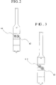
- FIG. 2 is an enlarged view of the vicinity of a first jet nozzle section and a second jet nozzle section of a jet-mixing apparatus according to a first embodiment of the present invention.
- FIG. 3 is an enlarged view of the vicinity of a first jet nozzle section and a second jet nozzle section of a jet-mixing apparatus according to a second embodiment of the present invention.
- FIG. 4 is a cross-sectional view of a rod of a jet-mixing apparatus according to the present invention.
- the jet-mixing apparatus 10 of the present invention comprises a drive unit 20 , thruster (feed unit) 3 and a rod 40 .
- a drive unit 20 As other required components not shown in the drawing, there are separately provided pumps for pressurized delivery of water, compressed air, ground improvement medium and reactant to the interior of the rod 40 .
- the drive unit 20 and thruster 30 can be of the same type as used in the prior art and the details thereof will be explained only to the extent necessary.
- the rod 40 shown in the drawing is a multiple-tube rod equipped with a first jet nozzle section 42 and a second jet nozzle section 44 having nozzles facing in substantially the same direction and further equipped above the first and second jet nozzle sections with a third jet nozzle section 46 having a nozzle facing in substantially the opposite direction from those of the first and second jet nozzle sections.
- Passages are provided inside the rod for supplying water, compressed air, ground improvement medium and reactant to the respective nozzle sections. The passages are used to supply material to be jetted to the respective nozzle sections.
- the rod may have a multiplex structure consisting of four tubes of different diameter for enabling water, compressed air, ground improvement medium and reactant to be individually pumped through the gaps between the tubes and jetted without intermixing.
- a mixing section for mixing compressed air and water is provided near the third jet nozzle section.
- no particular restriction is placed on the mixing method or the structure of the mixing section.
- the first jet nozzle section 42 is constituted as a nozzle for jetting ground improvement medium consisting mainly of a hardening material such as cement milk and the second jet nozzle section 44 is constituted as a nozzle for jetting reactant in substantially the same direction as the jet direction of the first jet nozzle section 42 .
- the shapes of the jet nozzle sections are not particularly limited and can be suitably determined taking into account the properties of the ground improvement medium and reactant used.
- the ground improvement medium and reactant used in the conventional jet-mixing method can be used in the present invention without modification.
- the main component of the ground improvement medium used in the conventional ground jet-mixing method is a hardening material such as cement milk. Further, it is also possible to mix a hardening material with surplus soil obtained by removing solids of larger than a predetermined diameter from mud discharged when the jet-mixing method is conducted and to use the mixture as ground improvement medium. Although it is possible to separate and remove solids by a method using a sieve or the like, the method used is not particularly specified.
- the reactant there is used water glass, sodium silicate or other such material that promotes hardening by reacting with cement milk or the like.
- the ground improvement medium and reactant are only required to harden or reform the ground by reacting when mixed, and the properties and chemical composition thereof are not particularly defined.
- the positional relationship between the first jet nozzle section 42 and second jet nozzle section 44 need only be such that the materials jetted thereby are jetted in substantially the same direction and need not be defined exactly.
- the simplest configuration would be to dispose the first and second jet nozzle sections immediately above and below each other. In the present invention, however, uneven mixing of the reactant and ground improvement medium is minimized by, as shown in FIGS. 2 and 3 , disposing the first and second jet nozzle sections in parallel or with a small vertical offset. Configurations having the first jet nozzle section 42 and second jet nozzle section 44 installed in the manner of FIGS. 2 and 3 are explained in detail below regarding the embodiments.
- the jet directions of the first jet nozzle section 42 and second jet nozzle section 44 are preferably parallel, the jet directions need not be absolutely parallel.
- the direction of the force acting on the rod is the direction of the resultant force of the forces produced by jetting in the two directions.
- the directions of the first jet nozzle section 42 and second jet nozzle section 44 can be defined as desired.
- the location of the third jet nozzle section 46 is likely to be easier to decide when the jet directions in which the reactant and ground improvement medium are jetted in parallel are unified.
- the third jet nozzle section 46 is constituted as a nozzle located above the first jet nozzle section 42 and second jet nozzle section 44 for jetting a mixture of compressed air and water in about the same direction as the reaction force produced by the jetting of material from the first and second jet nozzle sections.
- the shape of the nozzle of the third jet nozzle section is not particularly limited and can be any shape that enables the compressed air and water to be jetted at a prescribed pressure.
- the location and direction of the third jet nozzle section 46 must be determined taking into account the locations and directions of the first and second jet nozzle sections, the direction(s) in which they jet material and the force(s) produced with respect to the rod during jetting. For example, when the first and second jet nozzle sections jet in parallel in a specific direction, the third jet nozzle section should be installed to jet in the opposite direction from the first and second jet nozzle sections. When the jet directions of the first and second jet nozzle sections are slightly different, the direction of the third jet nozzle section is determined based on the resultant force produced by the first and second jet nozzle sections.
- the jet-mixing method of the present invention will now be explained in detail with reference to FIG. 1 , focusing particularly on the points of difference from the conventional jet-mixing method.
- the rod 40 is thrust into the ground to the desired depth.
- the rod is kept in rotation while being drawn upward.
- compressed air and water are jetted from the third jet nozzle section 46 to reach a prescribed distance (range), thereby forming a cylindrical bored region (ground improvement region) centered on the rod.
- the jet-mixing apparatus 10 of the present invention is configured to jet compressed air and water in only one direction, it can achieve the same actions and effects as the conventional apparatus that conducts bidirectional jetting when the rotational speed and the like are appropriately set. It should be noted that when the third jet nozzle section 46 commences jetting, the jet reaction force simultaneously acts on the rod.
- Mud composed of small stones, soil and water generated by cutting and crushing is discharged to the ground surface through the bored hole.
- the mud would ordinarily have to be treated as industrial waste but the present invention enables it to be reused by removing its water content, separating out solids of larger than a predetermined diameter, and then mixing the remaining mud with ground improvement medium.
- the present invention differs markedly from the prior art on this point.
- the rod 40 is gradually raised and when the lower first jet nozzle section 42 and second jet nozzle section 44 reach the ground improvement region, reactant is jetted from the second jet nozzle section 44 and ground improvement medium is jetted from the first jet nozzle section 42 .
- the jetted materials are mixed and churned into the ground improvement region.
- the first and second jet nozzle sections commence jetting, the resultant of the forces produced by the jetting simultaneously acts on the rod 40 in the direction opposite from the force produced by the third jet nozzle section 46 . Since the forces are applied in opposite directions, bending of the rod is minimized to prevent wobbling of the rotating rod.
- the mixed reactant and ground improvement medium react and solidify to form a pile.
- Embodiments of the jet-mixing method and jet-mixing apparatus characterized by the positioning of the first jet nozzle section 42 and second jet nozzle section 44 are explained in detail below with reference to the drawings.
- the jet-mixing method and jet-mixing apparatus of a first embodiment of the jet-mixing method and jet-mixing apparatus will be explained with reference to FIG. 2 .
- the jet-mixing apparatus 10 used for the jet-mixing method of this embodiment is characterized in the point that the first jet nozzle section 42 and second jet nozzle section 44 are installed side-by-side in the horizontal direction and their nozzles are directed in substantially the same direction so as to make their jet directions substantially parallel.
- the second jet nozzle section 44 is installed on the leading side relative to the rotational direction of the rod and the first jet nozzle section 42 is installed on the trailing side.
- the present invention teaches a jet-mixing method in which the second jet nozzle section 44 for jetting reactant is installed on the leading side of the rod rotation to mix the reactant with the ground first and the ground improvement medium is mixed later.
- the direction of rod rotation in this embodiment is indicated by an arrow in FIG. 1 .
- a configuration should be adopted in which the positions of the first and second jet nozzle sections are reversed from the foregoing.
- the first jet nozzle section 42 and second jet nozzle section 44 are positioned at the same height in the jet-mixing method and jet-mixing apparatus of this embodiment.
- the rotation of the rod therefore causes the reactant to be mixed with the ground first and the ground improvement medium to be jetted and mixed with the ground immediately thereafter. This is especially effective when it is desired to rapidly mix the reactant and ground improvement medium. It suffices to install the constituent first jet nozzle section 42 and second jet nozzle section 44 both at the same height. Although no particular restriction is placed on the nozzle angles, it is desirable for the jet directions of the jet nozzle sections to be as near parallel as possible.
- the jet-mixing method and jet-mixing apparatus of a second embodiment of the jet-mixing method and jet-mixing apparatus will be explained with reference to FIG. 3 .
- the jet-mixing apparatus 10 used for the jet-mixing method of this embodiment is characterized in the point that the second jet nozzle section 44 is located a prescribed distance above the first jet nozzle section 42 and the nozzles of the two jet nozzle sections are directed in substantially the same direction so as to make their jet directions substantially parallel.
- the second jet nozzle section 44 is installed on the leading side relative to the rotational direction of the rod and the first jet nozzle section 42 is installed on the trailing side.
- the second jet nozzle section 44 for jetting the reactant is located above the first jet nozzle section 42 so as to mix the reactant with the ground before the ground improvement medium.
- the distance by which the second jet nozzle section 44 positioned above the first jet nozzle section 42 is not particularly defined, an appropriate proximal location enabling the reactant and ground improvement medium to be uniformly blended should be selected.
Landscapes
- Engineering & Computer Science (AREA)
- Life Sciences & Earth Sciences (AREA)
- Mining & Mineral Resources (AREA)
- General Life Sciences & Earth Sciences (AREA)
- Environmental & Geological Engineering (AREA)
- Structural Engineering (AREA)
- Geology (AREA)
- Geochemistry & Mineralogy (AREA)
- Physics & Mathematics (AREA)
- Agronomy & Crop Science (AREA)
- Soil Sciences (AREA)
- Fluid Mechanics (AREA)
- Paleontology (AREA)
- Civil Engineering (AREA)
- General Engineering & Computer Science (AREA)
- Consolidation Of Soil By Introduction Of Solidifying Substances Into Soil (AREA)
Abstract
Description
Claims (10)
Priority Applications (1)
| Application Number | Priority Date | Filing Date | Title |
|---|---|---|---|
| US12/170,841 US7874766B2 (en) | 2008-07-10 | 2008-07-10 | Jet-mixing method and jet-mixing apparatus |
Applications Claiming Priority (1)
| Application Number | Priority Date | Filing Date | Title |
|---|---|---|---|
| US12/170,841 US7874766B2 (en) | 2008-07-10 | 2008-07-10 | Jet-mixing method and jet-mixing apparatus |
Publications (2)
| Publication Number | Publication Date |
|---|---|
| US20100006168A1 US20100006168A1 (en) | 2010-01-14 |
| US7874766B2 true US7874766B2 (en) | 2011-01-25 |
Family
ID=41504040
Family Applications (1)
| Application Number | Title | Priority Date | Filing Date |
|---|---|---|---|
| US12/170,841 Expired - Fee Related US7874766B2 (en) | 2008-07-10 | 2008-07-10 | Jet-mixing method and jet-mixing apparatus |
Country Status (1)
| Country | Link |
|---|---|
| US (1) | US7874766B2 (en) |
Cited By (1)
| Publication number | Priority date | Publication date | Assignee | Title |
|---|---|---|---|---|
| US20110110726A1 (en) * | 2009-11-06 | 2011-05-12 | Thomas Plahert | Jet grouting device with rotating roller bearing within casing pipe and rotating pipe |
Families Citing this family (4)
| Publication number | Priority date | Publication date | Assignee | Title |
|---|---|---|---|---|
| ITBO20130070A1 (en) * | 2013-02-19 | 2014-08-20 | Elas Geotecnica Srl | DEVICE, EQUIPMENT AND PROCEDURE FOR THE CONSOLIDATION OF LAND FOR INJECTION |
| ITPC20130020A1 (en) * | 2013-06-13 | 2014-12-14 | Francese Mauro Del | COMPUTERIZED POWER INJECTION SYSTEM FOR VALVE MULTIPLE ENTRY PIPES |
| GB2562389B (en) * | 2016-03-08 | 2022-03-02 | Halliburton Energy Services Inc | Rapid setting in situ cement plugs |
| JP6304730B1 (en) * | 2017-12-20 | 2018-04-04 | ケミカルグラウト株式会社 | Mud discharge promotion device and ground improvement method |
Citations (8)
| Publication number | Priority date | Publication date | Assignee | Title |
|---|---|---|---|---|
| US3763654A (en) * | 1971-11-08 | 1973-10-09 | K Matsushita | Pile driving and drawing apparatus |
| US4397588A (en) * | 1981-01-23 | 1983-08-09 | Vibroflotation Foundation Company | Method of constructing a compacted granular or stone column in soil masses and apparatus therefor |
| JP2000027173A (en) | 1998-07-10 | 2000-01-25 | Nit Co Ltd | Ground hardening layer formation method by polymerization jet |
| JP2000290991A (en) | 1999-04-02 | 2000-10-17 | Nit Co Ltd | Soil improvement method |
| US6231270B1 (en) * | 1999-05-27 | 2001-05-15 | Frank Cacossa | Apparatus and method of installing piles |
| US6241426B1 (en) * | 1999-05-25 | 2001-06-05 | Aerial Industrial, Inc. | Method for forming an interconnected underground structure |
| JP2001279661A (en) | 2000-03-31 | 2001-10-10 | Nippon Sogo Bosui Kk | High pressure injection agitating mixing device and high pressure injection agitating mixing construction method using this |
| JP2005113647A (en) | 2003-10-02 | 2005-04-28 | Eikou Sangyo Kk | Jet stirring method and jet stirring device |
-
2008
- 2008-07-10 US US12/170,841 patent/US7874766B2/en not_active Expired - Fee Related
Patent Citations (8)
| Publication number | Priority date | Publication date | Assignee | Title |
|---|---|---|---|---|
| US3763654A (en) * | 1971-11-08 | 1973-10-09 | K Matsushita | Pile driving and drawing apparatus |
| US4397588A (en) * | 1981-01-23 | 1983-08-09 | Vibroflotation Foundation Company | Method of constructing a compacted granular or stone column in soil masses and apparatus therefor |
| JP2000027173A (en) | 1998-07-10 | 2000-01-25 | Nit Co Ltd | Ground hardening layer formation method by polymerization jet |
| JP2000290991A (en) | 1999-04-02 | 2000-10-17 | Nit Co Ltd | Soil improvement method |
| US6241426B1 (en) * | 1999-05-25 | 2001-06-05 | Aerial Industrial, Inc. | Method for forming an interconnected underground structure |
| US6231270B1 (en) * | 1999-05-27 | 2001-05-15 | Frank Cacossa | Apparatus and method of installing piles |
| JP2001279661A (en) | 2000-03-31 | 2001-10-10 | Nippon Sogo Bosui Kk | High pressure injection agitating mixing device and high pressure injection agitating mixing construction method using this |
| JP2005113647A (en) | 2003-10-02 | 2005-04-28 | Eikou Sangyo Kk | Jet stirring method and jet stirring device |
Cited By (2)
| Publication number | Priority date | Publication date | Assignee | Title |
|---|---|---|---|---|
| US20110110726A1 (en) * | 2009-11-06 | 2011-05-12 | Thomas Plahert | Jet grouting device with rotating roller bearing within casing pipe and rotating pipe |
| US20110110727A1 (en) * | 2009-11-06 | 2011-05-12 | Thomas Plahert | Jet grouting apparatus for confined spaces and rapid mobilization requirements |
Also Published As
| Publication number | Publication date |
|---|---|
| US20100006168A1 (en) | 2010-01-14 |
Similar Documents
| Publication | Publication Date | Title |
|---|---|---|
| US7874766B2 (en) | Jet-mixing method and jet-mixing apparatus | |
| JPWO2006051865A1 (en) | Jet stirring method and jet stirring device | |
| JP2000290993A (en) | Ground mixing method and equipment | |
| JP2001073369A (en) | Press-fitting method for piles | |
| JP3626972B1 (en) | Jet stirring method and jet stirring device | |
| JP4684142B2 (en) | Injection mixing treatment method | |
| JPH0885941A (en) | System for mixing method with stirring | |
| JP4648764B2 (en) | Jet stirring method and jet stirring device | |
| JP4072968B2 (en) | Columnar pile building device and columnar pile building method | |
| KR100585422B1 (en) | Ground improvement reinforcement method and device | |
| JP5015558B2 (en) | Fiber reinforced cement ground improvement method | |
| JP2009275378A (en) | Fiber-reinforced cement-based soil improvement method | |
| JP2006144536A (en) | Ground improvement construction machine and ground improvement construction method | |
| JP3964904B2 (en) | Jet stirring method and jet stirring device | |
| JP2007077739A (en) | Jet grout type ground improvement construction method | |
| JP2009275379A (en) | Fiber-reinforced cement-based soil improvement method | |
| TWI415998B (en) | Jetting and agitating construction method and jetting and agitating device | |
| JP3247516B2 (en) | Injection pipe for ground improvement | |
| JPH03197714A (en) | Method and device for soil improvement | |
| JP3731669B2 (en) | Ground improvement system and construction method | |
| JPH0813471A (en) | Mechanical stirring method | |
| JP7599927B2 (en) | Method and equipment for treating raised portions of ground improvement bodies | |
| CN203594034U (en) | Pile-making vibrofluctuation device for vibrofluctuation powder-sprayed gravel pile | |
| KR200266675Y1 (en) | Mixer | |
| JPH02289719A (en) | Concrete sheet piles and press-fitting methods for the same sheet piles |
Legal Events
| Date | Code | Title | Description |
|---|---|---|---|
| AS | Assignment |
Owner name: FUJI KOEI INC., JAPAN Free format text: ASSIGNMENT OF ASSIGNORS INTEREST;ASSIGNOR:YANO, HIDEO;REEL/FRAME:021265/0339 Effective date: 20080630 Owner name: DAIEI SANGYO CO., LTD, JAPAN Free format text: ASSIGNMENT OF ASSIGNORS INTEREST;ASSIGNOR:YANO, HIDEO;REEL/FRAME:021265/0339 Effective date: 20080630 |
|
| AS | Assignment |
Owner name: FUJIJYUKI KOJI CO., LTD., JAPAN Free format text: ASSIGNMENT OF ASSIGNORS INTEREST;ASSIGNOR:FUJI KOEI INC.;REEL/FRAME:025331/0910 Effective date: 20101027 |
|
| FPAY | Fee payment |
Year of fee payment: 4 |
|
| AS | Assignment |
Owner name: DAIEI SANGYO CO., LTD., JAPAN Free format text: ASSIGNMENT OF ASSIGNORS INTEREST;ASSIGNOR:FUJIJYUKI KOJI CO., LTD.;REEL/FRAME:035083/0957 Effective date: 20150302 |
|
| FEPP | Fee payment procedure |
Free format text: MAINTENANCE FEE REMINDER MAILED (ORIGINAL EVENT CODE: REM.); ENTITY STATUS OF PATENT OWNER: SMALL ENTITY |
|
| LAPS | Lapse for failure to pay maintenance fees |
Free format text: PATENT EXPIRED FOR FAILURE TO PAY MAINTENANCE FEES (ORIGINAL EVENT CODE: EXP.); ENTITY STATUS OF PATENT OWNER: SMALL ENTITY |
|
| STCH | Information on status: patent discontinuation |
Free format text: PATENT EXPIRED DUE TO NONPAYMENT OF MAINTENANCE FEES UNDER 37 CFR 1.362 |
|
| FP | Lapsed due to failure to pay maintenance fee |
Effective date: 20190125 |