US7859961B2 - Optical disk recording method and optical disk recording apparatus - Google Patents

Optical disk recording method and optical disk recording apparatus Download PDF

Info

Publication number
US7859961B2
US7859961B2 US11/775,935 US77593507A US7859961B2 US 7859961 B2 US7859961 B2 US 7859961B2 US 77593507 A US77593507 A US 77593507A US 7859961 B2 US7859961 B2 US 7859961B2
Authority
US
United States
Prior art keywords
signal
reference clock
clock signal
optical disk
amount
Prior art date
Legal status (The legal status is an assumption and is not a legal conclusion. Google has not performed a legal analysis and makes no representation as to the accuracy of the status listed.)
Expired - Fee Related, expires
Application number
US11/775,935
Other versions
US20080019259A1 (en
Inventor
Tetsuji Nakaseko
Hisao Osabe
Current Assignee (The listed assignees may be inaccurate. Google has not performed a legal analysis and makes no representation or warranty as to the accuracy of the list.)
Sony Corp
Original Assignee
Sony Corp
Priority date (The priority date is an assumption and is not a legal conclusion. Google has not performed a legal analysis and makes no representation as to the accuracy of the date listed.)
Filing date
Publication date
Application filed by Sony Corp filed Critical Sony Corp
Assigned to SONY CORPORATION reassignment SONY CORPORATION ASSIGNMENT OF ASSIGNORS INTEREST (SEE DOCUMENT FOR DETAILS). Assignors: OSABE, HISAO, NAKASEKO, TETSUJI
Publication of US20080019259A1 publication Critical patent/US20080019259A1/en
Application granted granted Critical
Publication of US7859961B2 publication Critical patent/US7859961B2/en
Expired - Fee Related legal-status Critical Current
Adjusted expiration legal-status Critical

Links

Images

Classifications

    • GPHYSICS
    • G11INFORMATION STORAGE
    • G11BINFORMATION STORAGE BASED ON RELATIVE MOVEMENT BETWEEN RECORD CARRIER AND TRANSDUCER
    • G11B7/00Recording or reproducing by optical means, e.g. recording using a thermal beam of optical radiation by modifying optical properties or the physical structure, reproducing using an optical beam at lower power by sensing optical properties; Record carriers therefor
    • G11B7/004Recording, reproducing or erasing methods; Read, write or erase circuits therefor
    • G11B7/0045Recording
    • GPHYSICS
    • G11INFORMATION STORAGE
    • G11BINFORMATION STORAGE BASED ON RELATIVE MOVEMENT BETWEEN RECORD CARRIER AND TRANSDUCER
    • G11B7/00Recording or reproducing by optical means, e.g. recording using a thermal beam of optical radiation by modifying optical properties or the physical structure, reproducing using an optical beam at lower power by sensing optical properties; Record carriers therefor
    • G11B7/007Arrangement of the information on the record carrier, e.g. form of tracks, actual track shape, e.g. wobbled, or cross-section, e.g. v-shaped; Sequential information structures, e.g. sectoring or header formats within a track
    • G11B7/00736Auxiliary data, e.g. lead-in, lead-out, Power Calibration Area [PCA], Burst Cutting Area [BCA], control information
    • GPHYSICS
    • G11INFORMATION STORAGE
    • G11BINFORMATION STORAGE BASED ON RELATIVE MOVEMENT BETWEEN RECORD CARRIER AND TRANSDUCER
    • G11B20/00Signal processing not specific to the method of recording or reproducing; Circuits therefor
    • G11B20/10Digital recording or reproducing
    • G11B20/14Digital recording or reproducing using self-clocking codes
    • G11B20/1403Digital recording or reproducing using self-clocking codes characterised by the use of two levels
    • GPHYSICS
    • G11INFORMATION STORAGE
    • G11BINFORMATION STORAGE BASED ON RELATIVE MOVEMENT BETWEEN RECORD CARRIER AND TRANSDUCER
    • G11B7/00Recording or reproducing by optical means, e.g. recording using a thermal beam of optical radiation by modifying optical properties or the physical structure, reproducing using an optical beam at lower power by sensing optical properties; Record carriers therefor
    • G11B7/004Recording, reproducing or erasing methods; Read, write or erase circuits therefor
    • G11B7/005Reproducing
    • G11B7/0053Reproducing non-user data, e.g. wobbled address, prepits, BCA
    • GPHYSICS
    • G11INFORMATION STORAGE
    • G11BINFORMATION STORAGE BASED ON RELATIVE MOVEMENT BETWEEN RECORD CARRIER AND TRANSDUCER
    • G11B7/00Recording or reproducing by optical means, e.g. recording using a thermal beam of optical radiation by modifying optical properties or the physical structure, reproducing using an optical beam at lower power by sensing optical properties; Record carriers therefor
    • G11B7/007Arrangement of the information on the record carrier, e.g. form of tracks, actual track shape, e.g. wobbled, or cross-section, e.g. v-shaped; Sequential information structures, e.g. sectoring or header formats within a track
    • GPHYSICS
    • G11INFORMATION STORAGE
    • G11BINFORMATION STORAGE BASED ON RELATIVE MOVEMENT BETWEEN RECORD CARRIER AND TRANSDUCER
    • G11B7/00Recording or reproducing by optical means, e.g. recording using a thermal beam of optical radiation by modifying optical properties or the physical structure, reproducing using an optical beam at lower power by sensing optical properties; Record carriers therefor
    • G11B7/24Record carriers characterised by shape, structure or physical properties, or by the selection of the material
    • G11B7/2407Tracks or pits; Shape, structure or physical properties thereof
    • G11B7/24073Tracks
    • G11B7/24082Meandering
    • GPHYSICS
    • G11INFORMATION STORAGE
    • G11BINFORMATION STORAGE BASED ON RELATIVE MOVEMENT BETWEEN RECORD CARRIER AND TRANSDUCER
    • G11B7/00Recording or reproducing by optical means, e.g. recording using a thermal beam of optical radiation by modifying optical properties or the physical structure, reproducing using an optical beam at lower power by sensing optical properties; Record carriers therefor
    • G11B7/24Record carriers characterised by shape, structure or physical properties, or by the selection of the material
    • G11B7/2403Layers; Shape, structure or physical properties thereof
    • G11B7/24035Recording layers
    • G11B7/24038Multiple laminated recording layers

Definitions

  • the present invention contains subject matter related to Japanese Patent Application JP 2006-196406 filed in the Japanese Patent Office on Jul. 19, 2006, the entire contents of which are incorporated herein by reference.
  • the present invention relates to optical disk recording methods and optical disk recording apparatuses. More specifically, the present invention relates to an optical disk recording method for recording data on an optical disk including a groove track on which a wobble signal is recorded and a land track having land pre-pits carrying track position information, and an optical disk recording apparatus.
  • An optical disk such as a digital versatile disk-recordable/rewritable (DVD-R/RW) disk generally has, on a recording surface thereof, a groove track on which a wobble signal is recorded and a land track having land pre-pits carrying track position information.
  • DVD-R/RW digital versatile disk-recordable/rewritable
  • an optical pickup When desired data is written to such an optical disk using an optical disk recording apparatus, an optical pickup reads the wobble signal from the groove track to generate a recording reference clock signal from the wobble signal. The data is written to the optical disk on the basis of the reference clock signal.
  • the optical pickup further reads a pre-pit signal from the land track to reproduce, from the pre-pit signal, address/data information having a predetermined phase relationship with the wobble signal.
  • the data is written to the optical disk on the basis of the address/data information.
  • phase shift induced by crosstalk has an unfixed value but periodically fluctuates in accordance with the shape of the adjacent groove track, it is difficult to cancel the phase shift simply by applying an offset. Due to the phase shift, a recording position may not be located within a standard range when predetermined data is written to the optical disk.
  • FIG. 12 shows the relationship between a phase comparison reference counter and a pre-pit signal.
  • the phase comparison reference counter operates in response to the pre-pit signal.
  • a wobble signal is not affected by the influence of crosstalk, and has no phase difference from the pre-pit signal.
  • the wobble signal is affected by the influence of crosstalk, and has a phase difference from the pre-pit signal.
  • FIG. 13 shows phase comparison.
  • an interval of the recording end position relative to the recording start position corresponds to a period of n channel clocks, which are maximally affected by crosstalk.
  • the wobble signal is maximally affected by crosstalk in the opposite direction at the end of the recording operation in response to the n channel clocks, which are maximally affected by crosstalk, and the maximum phase difference amounts to n ⁇ 2 channel clocks.
  • the pre-pit signal is necessary.
  • the read rate of the pre-pit signal may be lowered during or after the recording of predetermined data, resulting in failure of phase shift correction.
  • optical disk capable of high-speed processing and having multiple recording layers, which does not depend on the quality of a pre-pit signal during recording.
  • an optical disk recording method for recording predetermined data on an optical disk on the basis of a first reference clock signal used for recording, the optical disk including a groove track having a wobble signal recorded thereon and a land track having a land pre-pit carrying track position information, the first reference clock signal being generated on the basis of the wobble signal reproduced from the optical disk.
  • the method includes the steps of reproducing a pre-pit signal from the optical disk; generating a second reference clock signal from the pre-pit signal; detecting an amount of phase shift of the first reference clock signal using the second reference clock signal; and correcting the first reference clock signal on the basis of an average value of the detected amount of phase shift.
  • an optical disk recording apparatus for recording predetermined data on an optical disk including a groove track having a wobble signal recorded thereon and a land track having a land pre-pit carrying track position information.
  • the apparatus includes wobble signal reproducing means for reproducing the wobble signal from the optical disk; first reference clock signal generating means for generating a first reference clock signal used for recording from the wobble signal, the predetermined data being recorded on the optical disk on the basis of the first reference clock signal; pre-pit signal reproducing means for reproducing a pre-pit signal from the optical disk; second reference clock signal generating means for generating a second reference clock signal from the pre-pit signal; shift-amount detecting means for detecting an amount of phase shift of the first reference clock signal using the second reference clock signal; and correcting means for correcting the first reference clock signal on the basis of an average value of the amount of phase shift detected by the shift-amount detecting means.
  • the shift-amount detecting means may include maximum-shift-amount detecting means for detecting a maximum amount of phase shift, and minimum-shift-amount detecting means for detecting a minimum amount of phase shift.
  • the average value of the amount of phase shift may be an intermediate value between the maximum amount of phase shift detected by the maximum-shift-amount detecting means and the minimum amount of phase shift detected by the minimum-shift-amount detecting means.
  • the shift-amount detecting means may include adding means for accumulating the amount of phase shift a predetermined number of times.
  • the average value of the amount of phase shift may be an average value of the amount of phase shift accumulated by the adding means.
  • the shift-amount detecting means may include interval detecting means for detecting an interval over which the amount of phase shift changes, and amplitude detecting means for detecting an amplitude of the change in the amount of phase shift.
  • the correcting means may correct the first reference clock signal on the basis of the interval and the amplitude.
  • the optical disk recording apparatus may further include phase-defect detecting means for detecting a phase defect of the wobble signal.
  • phase-defect detecting means detects a phase defect of the wobble signal, an amount of phase shift detected by the shift-amount detecting means in the detected phase defect may be ignored.
  • the optical disk recording apparatus may further include radio-frequency (RF) signal reproducing means for, when the optical disk has data recorded thereon, reproducing an RF signal from a region of the optical disk in which the data has been recorded, and third reference clock signal generating means for generating a third reference clock signal on the basis of the RF signal.
  • the shift-amount detecting means may detect an amount of phase shift of the first reference clock signal using the third reference clock signal.
  • a second reference clock signal is generated on the basis of a pre-pit signal, and an amount of phase shift of the first reference clock signal is detected on the basis of the second reference clock signal.
  • An average value of the detected amount of phase shift is used to correct the first reference clock signal, whereby the first reference clock signal that is less affected by the influence of crosstalk can be generated. Therefore, the recording operation can be started without any influence of crosstalk, and can be ended without any influence of crosstalk.
  • data is recorded onto an optical disk using the first reference clock signal, and the first reference clock signal is corrected using the second reference clock signal before starting the recording of the data onto the optical disk using the first reference clock signal. Therefore, the influence of crosstalk can be eliminated or reduced even if a pre-pit signal fails to be detected during the recording of the data onto the optical disk.
  • the first reference clock signal can be satisfactorily corrected using a third reference clock signal based on an RF signal.
  • FIG. 1 is a schematic block diagram showing a basic system configuration of an optical disk recording apparatus according to an embodiment of the present invention
  • FIG. 2 is a diagram showing an example of phase comparison
  • FIG. 3 is a diagram showing a recording state and a sequence for a recording reference clock reproduction PLL
  • FIG. 4 is a diagram showing adjustment of wobble phase comparison reference
  • FIG. 5 is a diagram showing the advantages of the embodiment of the present invention.
  • FIG. 6 is a schematic block diagram showing a system configuration of an optical disk recording apparatus according to another embodiment of the present invention.
  • FIG. 7 is a schematic block diagram showing a system configuration of an optical disk recording apparatus according to still another embodiment of the present invention.
  • FIG. 8 is a diagram showing an example of detection of phase error peak values
  • FIG. 9 is a schematic block diagram showing a system configuration of an optical disk recording apparatus according to still another embodiment of the present invention.
  • FIG. 10 is a schematic block diagram showing a system configuration of an optical disk recording apparatus according to still another embodiment of the present invention.
  • FIG. 11 is a diagram showing a recording state and a sequence for a recording reference clock reproduction PLL
  • FIG. 12 is a timing diagram showing a problem with a system of the related art.
  • FIG. 13 is a timing diagram showing another problem with a system of the related art.
  • FIG. 1 is a schematic block diagram showing a system configuration of an optical disk recording apparatus according to an embodiment of the present invention.
  • the optical disk recording apparatus includes an optical pickup 1 that irradiates laser light onto an optical disk D serving as a recording medium to read the laser light reflected from a signal recording surface of the optical disk D.
  • the optical pickup 1 outputs a wobble/pre-pit signal N 1 including a wobble signal read from a groove track and a pre-pit signal read from a land track.
  • the wobble/pre-pit signal N 1 is input to a signal amplifier 10 .
  • the signal amplifier 10 amplifies the wobble/pre-pit signal N 1 , and outputs an amplified wobble/pre-pit signal N 10 .
  • the amplified wobble/pre-pit signal N 10 is input to a wobble filter circuit 30 for desired filtering processing.
  • the amplified wobble/pre-pit signal N 10 subjected to the filtering processing is input to a wobble extraction circuit 31 to extract a wobble signal N 31 , and a wobble phase comparator 32 generates a first phase control signal N 32 for the wobble signal reference on the basis of the wobble signal N 31 .
  • the amplified wobble/pre-pit signal N 10 is also input to a pre-pit filter circuit 20 for desired filtering processing.
  • the amplified wobble/pre-pit signal N 10 subjected to the filtering processing is input to a pre-pit extraction circuit 21 to extract a pre-pit signal N 21 , and a pre-pit phase comparator 22 generates a second phase control signal N 22 for the pre-pit signal reference on the basis of the pre-pit signal N 21 .
  • FIG. 2 shows the timing in the wobble phase comparator 32 . Since one wobble cycle generally corresponds to a period of 186 channel clocks, the wobble phase comparator 32 is based on the outputs of a phase comparison counter provided at intervals of 186 channel clocks starting from a phase comparison reference. In FIG. 2 , phase comparison is performed at the rising edge of the wobble signal N 31 . If the wobble phase comparator 32 has a count value less than 186/2, the measured value is determined as a phase error value. If the wobble phase comparator 32 has a count value not less than 186/2, a value obtained by subtracting 186 from the count value is determined as an error value.
  • the optical disk recording apparatus further includes a sequencer 40 implemented by a general-purpose central processing unit (CPU).
  • the sequencer 40 outputs a phase-control-signal selection signal N 40 for selecting a phase control signal to be input to a phase-locked loop (PLL) for generating a recording reference clock signal according to the state of a PLL that is to generate a reference clock signal used for recording on the optical disk D or the recording status.
  • PLL phase-locked loop
  • first phase control signal N 32 is output as a phase control signal N 41 selected and output from a selection output circuit 41 on the basis of the phase-control-signal selection signal N 40 , a first PLL circuit G 1 generates a first reference clock signal. If the second phase control signal N 22 is output from the selection output circuit 41 , a second PLL circuit G 2 generates a second reference clock signal.
  • the first and second PLL circuits G 1 and G 2 include a filter circuit 50 and a voltage-controlled oscillator (VCO) circuit 51 .
  • VCO voltage-controlled oscillator
  • a frequency divider 53 in the first PLL circuit G 1 divides the frequency of the first reference clock signal to generate a phase comparison reference.
  • a frequency divider 52 in the second PLL circuit G 2 divides the frequency of the second reference clock signal to generate a phase comparison reference.
  • FIG. 3 shows an example of the operation sequence of the optical disk recording apparatus of the present embodiment.
  • the sequencer 40 sets the second phase control signal N 22 for the pre-pit signal reference as a phase control signal to be input to a PLL for generating a reference clock signal until the first PLL circuit G 1 that is to generate the first reference clock signal used for recording has been locked before the recording on the optical disk D. Therefore, during reproduction of the reference clock signal using the second phase control signal N 22 for the pre-pit signal reference, the reference clock signal is not affected by the influence of crosstalk.
  • a maximum-shift-amount (maximum phase error) detection circuit 60 detects a maximum phase error, i.e., a maximum amount of phase shift, of the wobble signal using the second reference clock signal generated by the second PLL circuit G 2 .
  • a minimum-shift-amount (minimum phase error) detection circuit 61 detects a minimum phase error of the wobble signal.
  • a phase error analysis circuit 62 determines, as an average amount of shift, an intermediate value between the maximum phase error detected by the maximum-shift-amount detection circuit 60 and the minimum phase error detected by the minimum-shift-amount detection circuit 61 , and detects the center position of phase-shift fluctuations caused by crosstalk, i.e., an ideal wobble phase control reference point free from any influence of crosstalk.
  • the average amount of shift is input to the wobble phase comparator 32 as phase control reference offset information to adjust the first phase control signal N 32 for the wobble signal reference.
  • the center position of phase-shift fluctuations caused by crosstalk may also be determined from records of maximum and minimum values using a digital signal processor (DSP). Therefore, the center position can be determined with higher accuracy.
  • DSP digital signal processor
  • the first phase control signal N 32 is adjusted by, as shown in FIG. 4 , applying the amount of offset of the phase control reference point detected by the phase error analysis circuit 62 to the phase comparison counter to displace the phase comparison reference.
  • phase comparison reference for the wobble signal can coincide with the phase comparison reference for the pre-pit signal, and therefore the displacement of the recording position can be reduced to a half of that when the adjustment is not performed.
  • the average amount of shift is determined using the maximum-shift-amount detection circuit 60 and the minimum-shift-amount detection circuit 61 .
  • an integrator 70 may be provided to accumulate the amount of phase shift a predetermined number of times to determine the accumulated amount of phase shift.
  • a phase error analysis circuit 62 ′ determines an average value of the accumulated amount of phase shift to detect the average amount of shift. The detected average amount of shift may be used as the amount of offset of the phase control reference point.
  • the integrator 70 allows the phase comparison reference for the wobble signal to coincide with that for the pre-pit signal using a simple structure, and the displacement of the recording position can be reduced to a half of that when the adjustment is not performed.
  • periodic phase-shift fluctuations output from the wobble phase comparator 32 may be analyzed to determine an offset, and the offset may be added to the periodic phase-shift fluctuations to reduce the influence of crosstalk.
  • the optical disk recording apparatus includes an interval detection (crosstalk interval analysis) circuit 80 that detects an interval over which the amount of phase shift changes due to crosstalk, and an amplitude detection (phase error peak value detection) circuit 81 that detects the amplitude of the change in the amount of phase shift.
  • interval detection crosstalk interval analysis
  • amplitude detection phase error peak value detection
  • the amount of shift of the phase comparison reference for the wobble signal periodically fluctuates due to crosstalk, and peaks appear at constant intervals. Therefore, the amplitude of the change in the amount of shift is detected by comparing the peak position of the current amount of shift with that of the previous amount of shift. Frequency analysis of crosstalk is conducted to provide information concerning the timing of detection of peaks.
  • a defect detection circuit 90 serving as a phase-defect detector detecting a phase defect of the wobble signal may be provided.
  • the defect detection circuit 90 detects a defect in the phase of the wobble signal output from the wobble phase comparator 32 , an amount of shift detected in the detected defect portion is ignored to prevent the occurrence of malfunction due to a defective signal caused by scratches on the medium or the like.
  • the quality of the wobble signal may be degraded by scratches on the medium as well as the phase shift induced by crosstalk.
  • phase-shift fluctuations induced by crosstalk can be more accurately detected.
  • the optical disk recording apparatus when the optical disk D is not blank and is recorded with predetermined data, it is difficult to read a pre-pit signal from the region where the data has been recorded. Therefore, the second reference clock signal based on the pre-pit signal may not be generated.
  • an amplified signal N 10 ′ is input to an RF signal filter circuit 100 for predetermined filtering processing.
  • An amplified signal N 100 subjected to the filtering processing is input to an RF signal extraction circuit 101 to extract an RF signal N 101 , and an RF signal phase comparator 102 generates a third phase control signal N 102 for the RF signal reference on the basis of the RF signal N 101 .
  • the PLL circuit is locked using the third phase control signal N 102 instead of the second phase control signal N 22 , thereby correcting the first phase control signal N 32 .
  • FIG. 11 shows an example of the operation sequence of the optical disk recording apparatus using an RF signal.
  • the sequencer 40 sets the third phase control signal N 102 for the RF signal reference as a phase control signal to be input to a PLL for generating a reference clock signal until the first PLL circuit G 1 that is to generate the first reference clock signal used for recording has been locked before the recording on the optical disk D. Therefore, during reproduction of the reference clock signal using the third phase control signal N 102 for the RF signal reference, the reference clock signal is not affected by the influence of crosstalk.
  • the phase control reference is adjusted to a wobble phase comparator on the basis of an RF signal instead of a pre-pit signal. This ensures accurate correction.

Abstract

An optical disk recording method for recording predetermined data on an optical disk on the basis of a first reference clock signal used for recording, the optical disk including a groove track having a wobble signal recorded thereon and a land track having a land pre-pit carrying track position information, the first reference clock signal being generated on the basis of the wobble signal reproduced from the optical disk, includes the steps of reproducing a pre-pit signal from the optical disk; generating a second reference clock signal from the pre-pit signal; detecting an amount of phase shift of the first reference clock signal using the second reference clock signal; and correcting the first reference clock signal on the basis of an average value of the detected amount of phase shift.

Description

CROSS REFERENCES TO RELATED APPLICATIONS
The present invention contains subject matter related to Japanese Patent Application JP 2006-196406 filed in the Japanese Patent Office on Jul. 19, 2006, the entire contents of which are incorporated herein by reference.
BACKGROUND OF THE INVENTION
1. Field of the Invention
The present invention relates to optical disk recording methods and optical disk recording apparatuses. More specifically, the present invention relates to an optical disk recording method for recording data on an optical disk including a groove track on which a wobble signal is recorded and a land track having land pre-pits carrying track position information, and an optical disk recording apparatus.
2. Description of the Related Art
An optical disk such as a digital versatile disk-recordable/rewritable (DVD-R/RW) disk generally has, on a recording surface thereof, a groove track on which a wobble signal is recorded and a land track having land pre-pits carrying track position information.
When desired data is written to such an optical disk using an optical disk recording apparatus, an optical pickup reads the wobble signal from the groove track to generate a recording reference clock signal from the wobble signal. The data is written to the optical disk on the basis of the reference clock signal.
In the optical disk recording apparatus, the optical pickup further reads a pre-pit signal from the land track to reproduce, from the pre-pit signal, address/data information having a predetermined phase relationship with the wobble signal. The data is written to the optical disk on the basis of the address/data information.
With the recent progress on high-density optical disks, there has been a tendency to narrow the track pitch between the groove track and the land track. Thus, when a beam is irradiated onto the optical disk from the optical pickup, the phase of the wobble signal is likely to change due to the signal leakage from the adjacent groove track. The influence of the adjacent groove track, which causes such changes in the phase of the wobble signal, is called “crosstalk”.
Since the phase shift induced by crosstalk has an unfixed value but periodically fluctuates in accordance with the shape of the adjacent groove track, it is difficult to cancel the phase shift simply by applying an offset. Due to the phase shift, a recording position may not be located within a standard range when predetermined data is written to the optical disk.
FIG. 12 shows the relationship between a phase comparison reference counter and a pre-pit signal. As shown in FIG. 12, the phase comparison reference counter operates in response to the pre-pit signal. At time t0, a wobble signal is not affected by the influence of crosstalk, and has no phase difference from the pre-pit signal. However, at time t1, the wobble signal is affected by the influence of crosstalk, and has a phase difference from the pre-pit signal.
FIG. 13 shows phase comparison. As shown in FIG. 13, if the recording operation starts at time t0 and ends at time t2, an interval of the recording end position relative to the recording start position corresponds to a period of n channel clocks, which are maximally affected by crosstalk. On the other hand, if the recording operation starts at time t1 and ends at time t2, the wobble signal is maximally affected by crosstalk in the opposite direction at the end of the recording operation in response to the n channel clocks, which are maximally affected by crosstalk, and the maximum phase difference amounts to n×2 channel clocks.
To solve such a problem, a method of feeding back a phase difference between a wobble signal and a pre-pit signal to correct a phase shift of the wobble signal has been proposed (see, for example, Japanese Unexamined Patent Application Publication No. 2005-322407).
SUMMARY OF THE INVENTION
In the case where a phase difference between a wobble signal and a pre-pit signal is fed back to correct a phase shift of the wobble signal, the pre-pit signal is necessary. However, with the recent high-speed recording or reproduction or multiple recording layers, the read rate of the pre-pit signal may be lowered during or after the recording of predetermined data, resulting in failure of phase shift correction.
It is therefore desirable to provide an optical disk capable of high-speed processing and having multiple recording layers, which does not depend on the quality of a pre-pit signal during recording.
According to an embodiment of the present invention, there is provided an optical disk recording method for recording predetermined data on an optical disk on the basis of a first reference clock signal used for recording, the optical disk including a groove track having a wobble signal recorded thereon and a land track having a land pre-pit carrying track position information, the first reference clock signal being generated on the basis of the wobble signal reproduced from the optical disk. The method includes the steps of reproducing a pre-pit signal from the optical disk; generating a second reference clock signal from the pre-pit signal; detecting an amount of phase shift of the first reference clock signal using the second reference clock signal; and correcting the first reference clock signal on the basis of an average value of the detected amount of phase shift.
According to another embodiment of the present invention, there is provided an optical disk recording apparatus for recording predetermined data on an optical disk including a groove track having a wobble signal recorded thereon and a land track having a land pre-pit carrying track position information. The apparatus includes wobble signal reproducing means for reproducing the wobble signal from the optical disk; first reference clock signal generating means for generating a first reference clock signal used for recording from the wobble signal, the predetermined data being recorded on the optical disk on the basis of the first reference clock signal; pre-pit signal reproducing means for reproducing a pre-pit signal from the optical disk; second reference clock signal generating means for generating a second reference clock signal from the pre-pit signal; shift-amount detecting means for detecting an amount of phase shift of the first reference clock signal using the second reference clock signal; and correcting means for correcting the first reference clock signal on the basis of an average value of the amount of phase shift detected by the shift-amount detecting means.
The shift-amount detecting means may include maximum-shift-amount detecting means for detecting a maximum amount of phase shift, and minimum-shift-amount detecting means for detecting a minimum amount of phase shift. The average value of the amount of phase shift may be an intermediate value between the maximum amount of phase shift detected by the maximum-shift-amount detecting means and the minimum amount of phase shift detected by the minimum-shift-amount detecting means.
The shift-amount detecting means may include adding means for accumulating the amount of phase shift a predetermined number of times. The average value of the amount of phase shift may be an average value of the amount of phase shift accumulated by the adding means.
The shift-amount detecting means may include interval detecting means for detecting an interval over which the amount of phase shift changes, and amplitude detecting means for detecting an amplitude of the change in the amount of phase shift. The correcting means may correct the first reference clock signal on the basis of the interval and the amplitude.
The optical disk recording apparatus may further include phase-defect detecting means for detecting a phase defect of the wobble signal. When the phase-defect detecting means detects a phase defect of the wobble signal, an amount of phase shift detected by the shift-amount detecting means in the detected phase defect may be ignored.
The optical disk recording apparatus may further include radio-frequency (RF) signal reproducing means for, when the optical disk has data recorded thereon, reproducing an RF signal from a region of the optical disk in which the data has been recorded, and third reference clock signal generating means for generating a third reference clock signal on the basis of the RF signal. The shift-amount detecting means may detect an amount of phase shift of the first reference clock signal using the third reference clock signal.
According to an embodiment of the present invention, when a first reference clock signal used for recording is generated on the basis of a wobble signal, a second reference clock signal is generated on the basis of a pre-pit signal, and an amount of phase shift of the first reference clock signal is detected on the basis of the second reference clock signal. An average value of the detected amount of phase shift is used to correct the first reference clock signal, whereby the first reference clock signal that is less affected by the influence of crosstalk can be generated. Therefore, the recording operation can be started without any influence of crosstalk, and can be ended without any influence of crosstalk.
In particular, data is recorded onto an optical disk using the first reference clock signal, and the first reference clock signal is corrected using the second reference clock signal before starting the recording of the data onto the optical disk using the first reference clock signal. Therefore, the influence of crosstalk can be eliminated or reduced even if a pre-pit signal fails to be detected during the recording of the data onto the optical disk.
Further, in the case where it is difficult to generate the second reference clock signal because the data is recorded on the optical disk, the first reference clock signal can be satisfactorily corrected using a third reference clock signal based on an RF signal.
BRIEF DESCRIPTION OF THE DRAWINGS
FIG. 1 is a schematic block diagram showing a basic system configuration of an optical disk recording apparatus according to an embodiment of the present invention;
FIG. 2 is a diagram showing an example of phase comparison;
FIG. 3 is a diagram showing a recording state and a sequence for a recording reference clock reproduction PLL;
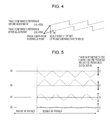
FIG. 4 is a diagram showing adjustment of wobble phase comparison reference;
FIG. 5 is a diagram showing the advantages of the embodiment of the present invention;
FIG. 6 is a schematic block diagram showing a system configuration of an optical disk recording apparatus according to another embodiment of the present invention;
FIG. 7 is a schematic block diagram showing a system configuration of an optical disk recording apparatus according to still another embodiment of the present invention;
FIG. 8 is a diagram showing an example of detection of phase error peak values;
FIG. 9 is a schematic block diagram showing a system configuration of an optical disk recording apparatus according to still another embodiment of the present invention;
FIG. 10 is a schematic block diagram showing a system configuration of an optical disk recording apparatus according to still another embodiment of the present invention;
FIG. 11 is a diagram showing a recording state and a sequence for a recording reference clock reproduction PLL;
FIG. 12 is a timing diagram showing a problem with a system of the related art; and
FIG. 13 is a timing diagram showing another problem with a system of the related art.
DESCRIPTION OF THE PREFERRED EMBODIMENTS
FIG. 1 is a schematic block diagram showing a system configuration of an optical disk recording apparatus according to an embodiment of the present invention.
The optical disk recording apparatus includes an optical pickup 1 that irradiates laser light onto an optical disk D serving as a recording medium to read the laser light reflected from a signal recording surface of the optical disk D. The optical pickup 1 outputs a wobble/pre-pit signal N1 including a wobble signal read from a groove track and a pre-pit signal read from a land track.
The wobble/pre-pit signal N1 is input to a signal amplifier 10. The signal amplifier 10 amplifies the wobble/pre-pit signal N1, and outputs an amplified wobble/pre-pit signal N10.
The amplified wobble/pre-pit signal N10 is input to a wobble filter circuit 30 for desired filtering processing. The amplified wobble/pre-pit signal N10 subjected to the filtering processing is input to a wobble extraction circuit 31 to extract a wobble signal N31, and a wobble phase comparator 32 generates a first phase control signal N32 for the wobble signal reference on the basis of the wobble signal N31.
The amplified wobble/pre-pit signal N10 is also input to a pre-pit filter circuit 20 for desired filtering processing. The amplified wobble/pre-pit signal N10 subjected to the filtering processing is input to a pre-pit extraction circuit 21 to extract a pre-pit signal N21, and a pre-pit phase comparator 22 generates a second phase control signal N22 for the pre-pit signal reference on the basis of the pre-pit signal N21.
FIG. 2 shows the timing in the wobble phase comparator 32. Since one wobble cycle generally corresponds to a period of 186 channel clocks, the wobble phase comparator 32 is based on the outputs of a phase comparison counter provided at intervals of 186 channel clocks starting from a phase comparison reference. In FIG. 2, phase comparison is performed at the rising edge of the wobble signal N31. If the wobble phase comparator 32 has a count value less than 186/2, the measured value is determined as a phase error value. If the wobble phase comparator 32 has a count value not less than 186/2, a value obtained by subtracting 186 from the count value is determined as an error value.
The optical disk recording apparatus further includes a sequencer 40 implemented by a general-purpose central processing unit (CPU). The sequencer 40 outputs a phase-control-signal selection signal N40 for selecting a phase control signal to be input to a phase-locked loop (PLL) for generating a recording reference clock signal according to the state of a PLL that is to generate a reference clock signal used for recording on the optical disk D or the recording status.
If the first phase control signal N32 is output as a phase control signal N41 selected and output from a selection output circuit 41 on the basis of the phase-control-signal selection signal N40, a first PLL circuit G1 generates a first reference clock signal. If the second phase control signal N22 is output from the selection output circuit 41, a second PLL circuit G2 generates a second reference clock signal. In FIG. 1, the first and second PLL circuits G1 and G2 include a filter circuit 50 and a voltage-controlled oscillator (VCO) circuit 51.
A frequency divider 53 in the first PLL circuit G1 divides the frequency of the first reference clock signal to generate a phase comparison reference. A frequency divider 52 in the second PLL circuit G2 divides the frequency of the second reference clock signal to generate a phase comparison reference.
FIG. 3 shows an example of the operation sequence of the optical disk recording apparatus of the present embodiment. In the optical disk recording apparatus, the sequencer 40 sets the second phase control signal N22 for the pre-pit signal reference as a phase control signal to be input to a PLL for generating a reference clock signal until the first PLL circuit G1 that is to generate the first reference clock signal used for recording has been locked before the recording on the optical disk D. Therefore, during reproduction of the reference clock signal using the second phase control signal N22 for the pre-pit signal reference, the reference clock signal is not affected by the influence of crosstalk.
A maximum-shift-amount (maximum phase error) detection circuit 60 detects a maximum phase error, i.e., a maximum amount of phase shift, of the wobble signal using the second reference clock signal generated by the second PLL circuit G2. A minimum-shift-amount (minimum phase error) detection circuit 61 detects a minimum phase error of the wobble signal.
A phase error analysis circuit 62 determines, as an average amount of shift, an intermediate value between the maximum phase error detected by the maximum-shift-amount detection circuit 60 and the minimum phase error detected by the minimum-shift-amount detection circuit 61, and detects the center position of phase-shift fluctuations caused by crosstalk, i.e., an ideal wobble phase control reference point free from any influence of crosstalk.
The average amount of shift is input to the wobble phase comparator 32 as phase control reference offset information to adjust the first phase control signal N32 for the wobble signal reference.
The center position of phase-shift fluctuations caused by crosstalk may also be determined from records of maximum and minimum values using a digital signal processor (DSP). Therefore, the center position can be determined with higher accuracy.
The first phase control signal N32 is adjusted by, as shown in FIG. 4, applying the amount of offset of the phase control reference point detected by the phase error analysis circuit 62 to the phase comparison counter to displace the phase comparison reference.
If the adjustment based on the phase control reference point detected by the phase error analysis circuit 62 is not performed, as shown in part (a) or (b) of FIG. 5, there is a deviation between the phase comparison references for the pre-pit signal and the wobble signal, leading to a possibility of a larger displacement of the recording position. With the adjustment based on the phase control reference point, as shown in part (c) of FIG. 5, the phase comparison reference for the wobble signal can coincide with the phase comparison reference for the pre-pit signal, and therefore the displacement of the recording position can be reduced to a half of that when the adjustment is not performed.
In the above-described embodiment, the average amount of shift is determined using the maximum-shift-amount detection circuit 60 and the minimum-shift-amount detection circuit 61. According to another embodiment of the present invention, as shown in FIG. 6, an integrator 70 may be provided to accumulate the amount of phase shift a predetermined number of times to determine the accumulated amount of phase shift. A phase error analysis circuit 62′ determines an average value of the accumulated amount of phase shift to detect the average amount of shift. The detected average amount of shift may be used as the amount of offset of the phase control reference point.
The integrator 70 allows the phase comparison reference for the wobble signal to coincide with that for the pre-pit signal using a simple structure, and the displacement of the recording position can be reduced to a half of that when the adjustment is not performed.
In an optical disk recording apparatus according to a further embodiment of the present invention, as shown in FIG. 7, periodic phase-shift fluctuations output from the wobble phase comparator 32 may be analyzed to determine an offset, and the offset may be added to the periodic phase-shift fluctuations to reduce the influence of crosstalk.
Specifically, the optical disk recording apparatus includes an interval detection (crosstalk interval analysis) circuit 80 that detects an interval over which the amount of phase shift changes due to crosstalk, and an amplitude detection (phase error peak value detection) circuit 81 that detects the amplitude of the change in the amount of phase shift. Periodic phase-shift fluctuations are analyzed, and an offset is applied to the phase comparator 32 for the wobble signal in the direction opposite to that of the periodic phase-shift fluctuations. Therefore, as shown in part (d) of FIG. 5, the periodic phase-shift fluctuations caused by crosstalk can be canceled.
As shown in FIG. 8, the amount of shift of the phase comparison reference for the wobble signal periodically fluctuates due to crosstalk, and peaks appear at constant intervals. Therefore, the amplitude of the change in the amount of shift is detected by comparing the peak position of the current amount of shift with that of the previous amount of shift. Frequency analysis of crosstalk is conducted to provide information concerning the timing of detection of peaks.
According to a still further embodiment of the present invention, as shown in FIG. 9, a defect detection circuit 90 serving as a phase-defect detector detecting a phase defect of the wobble signal may be provided. When the defect detection circuit 90 detects a defect in the phase of the wobble signal output from the wobble phase comparator 32, an amount of shift detected in the detected defect portion is ignored to prevent the occurrence of malfunction due to a defective signal caused by scratches on the medium or the like.
The quality of the wobble signal may be degraded by scratches on the medium as well as the phase shift induced by crosstalk.
If the signal quality is low, the amount of phase shift may not be correctly detected. An analysis based on such an incorrect phase error may provide inaccurate detection of the center of phase-shift fluctuations induced by crosstalk. Therefore, by detecting and eliminating a defective phase error, the center of the phase-shift fluctuations induced by crosstalk can be more accurately detected.
Furthermore, in the optical disk recording apparatus, when the optical disk D is not blank and is recorded with predetermined data, it is difficult to read a pre-pit signal from the region where the data has been recorded. Therefore, the second reference clock signal based on the pre-pit signal may not be generated.
To address this problem, as shown in FIG. 10, an amplified signal N10′ is input to an RF signal filter circuit 100 for predetermined filtering processing. An amplified signal N100 subjected to the filtering processing is input to an RF signal extraction circuit 101 to extract an RF signal N101, and an RF signal phase comparator 102 generates a third phase control signal N102 for the RF signal reference on the basis of the RF signal N101.
The PLL circuit is locked using the third phase control signal N102 instead of the second phase control signal N22, thereby correcting the first phase control signal N32.
FIG. 11 shows an example of the operation sequence of the optical disk recording apparatus using an RF signal. In the optical disk recording apparatus, the sequencer 40 sets the third phase control signal N102 for the RF signal reference as a phase control signal to be input to a PLL for generating a reference clock signal until the first PLL circuit G1 that is to generate the first reference clock signal used for recording has been locked before the recording on the optical disk D. Therefore, during reproduction of the reference clock signal using the third phase control signal N102 for the RF signal reference, the reference clock signal is not affected by the influence of crosstalk.
With the use of the third phase control signal N102 for the RF signal reference, even if it is difficult to detect a pre-pit signal from a recorded region of the optical disk D or from a high-speed multilayer medium suitable for high-speed recording or having multiple layers, the phase control reference is adjusted to a wobble phase comparator on the basis of an RF signal instead of a pre-pit signal. This ensures accurate correction.
It should be understood by those skilled in the art that various modifications, combinations, sub-combinations and alterations may occur depending on design requirements and other factors insofar as they are within the scope of the appended claims or the equivalents thereof.

Claims (8)

1. An optical disk recording method for recording predetermined data on an optical disk on the basis of a first reference clock signal used for recording, the optical disk including a groove track having a wobble signal recorded thereon and a land track having a land pre-pit carrying track position information, the first reference clock signal being generated on the basis of the wobble signal reproduced from the optical disk, the method comprising the steps of:
reproducing a pre-pit signal from the optical disk;
generating a second reference clock signal from the pre-pit signal;
detecting an amount of phase shift of the first reference clock signal using the second reference clock signal; and
correcting the first reference clock signal on the basis of an average value of the detected amount of phase shift,
wherein,
a first phase control signal or a second phase control signal is selected based upon a phase-control-signal-selection signal such that:
if the first phase control signal is selected, then the first reference clock signal is generated, and
if the second phase control signal is selected, then the second reference clock signal is generated.
2. An optical disk recording apparatus for recording predetermined data on an optical disk including a groove track having a wobble signal recorded thereon and a land track having a land pre-pit carrying track position information, the apparatus comprising:
wobble signal reproducing means for reproducing the wobble signal from the optical disk;
selection output circuit to select a first phase control signal or a second phase control signal based upon a phase-control-signal-selection signal;
first reference clock signal generating means for generating a first reference clock signal used for recording from the wobble signal, the predetermined data being recorded on the optical disk on the basis of the first reference clock signal;
pre-pit signal reproducing means for reproducing a pre-pit signal from the optical disk;
second reference clock signal generating means for generating a second reference clock signal from the pre-pit signal;
shift-amount detecting means for detecting an amount of phase shift of the first reference clock signal using the second reference clock signal; and
correcting means for correcting the first reference clock signal on the basis of an average value of the amount of phase shift detected by the shift-amount detecting means
wherein,
if the first phase control signal is selected, then the first reference clock signal is generated, and
if the second phase control signal is selected, then the second reference clock signal is generated.
3. The optical disk recording apparatus according to claim 2, wherein:
the shift-amount detecting means includes maximum-shift-amount detecting means for detecting a maximum amount of phase shift, and minimum-shift-amount detecting means for detecting a minimum amount of phase shift; and
the average value of the amount of phase shift is an intermediate value between the maximum amount of phase shift detected by the maximum-shift-amount detecting means and the minimum amount of phase shift detected by the minimum-shift-amount detecting means.
4. The optical disk recording apparatus according to claim 2, wherein:
the shift-amount detecting means includes adding means for accumulating the amount of phase shift a predetermined number of times; and
the average value of the amount of phase shift is an average value of the amount of phase shift accumulated by the adding means.
5. The optical disk recording apparatus according to claim 2, wherein:
the shift-amount detecting means includes
interval detecting means for detecting an interval over which the amount of phase shift changes, and
amplitude detecting means for detecting an amplitude of the change in the amount of phase shift; and
the correcting means corrects the first reference clock signal on the basis of the interval and the amplitude.
6. An optical disk recording apparatus for recording predetermined data on an optical disk including a groove track having a wobble signal recorded thereon and a land track having a land pre-pit carrying track position information, the apparatus comprising:
wobble signal reproducing means for reproducing the wobble signal from the optical disk;
first reference clock signal generating means for generating a first reference clock signal used for recording from the wobble signal, the predetermined data being recorded on the optical disk on the basis of the first reference clock signal;
pre-pit signal reproducing means for reproducing a pre-pit signal m the optical disk;
second reference clock signal generating means for generating a second reference clock signal from the pre-pit signal;
shift-amount detecting means for detecting an amount of phase shift of the first reference clock signal using the second reference clock signal;
correcting means for correcting the first reference clock signal on the basis of an average value of the amount of phase shift detected by the shift-amount detecting means; and
phase-defect detecting means for detecting a phase defect of the wobble signal,
wherein when the phase-defect detecting means detects a phase defect of the wobble signal, an amount of phase shift detected by the shift-amount detecting means in the detected phase defect is ignored.
7. An optical disk recording apparatus for recording predetermined data on an optical disk including a groove track having a wobble signal recorded thereon and a land track having a land pre-pit carrying track position information, the apparatus comprising:
wobble signal reproducing means for reproducing the wobble signal from the optical disk;
first reference clock signal generating means for generating a first reference clock signal used for recording from the wobble signal, the predetermined data being recorded on the optical disk on the basis of the first reference clock signal;
pre-pit signal reproducing means for reproducing a pre-pit signal from the optical disk;
second reference clock signal generating means for generating a second reference clock signal from the pre-pit signal;
shift-amount detecting means for detecting an amount of phase shift of the first reference clock signal using the second reference clock signal;
correcting means for correcting the first reference clock signal on the basis of an average value of the amount of phase shift detected by the shift-amount detecting means;
radio-frequency signal reproducing means for, when the optical disk has data recorded thereon, reproducing a radio-frequency signal from a region of the optical disk in which the data has been recorded; and
third reference clock signal generating means for generating a third reference clock signal on the basis of the radio-frequency signal,
wherein the shift-amount detecting means detects an amount of phase shift of the first reference clock signal using the third reference clock signal.
8. An optical disk recording apparatus for recording predetermined data on an optical disk including a groove track having a wobble signal recorded thereon and a land track having a land pre-pit carrying track position information, the apparatus comprising:
a wobble signal reproducing unit reproducing the wobble signal from the optical disk;
selection output circuit to select a first phase control signal or a second phase control signal based upon a phase-control-signal-selection signal;
a first reference clock signal generator generating a first reference clock signal used for recording from the wobble signal, the predetermined data being recorded on the optical disk on the basis of the first reference clock signal;
a pre-pit signal reproducing unit reproducing a pre-pit signal from the optical disk;
a second reference clock signal generator generating a second reference clock signal from the pre-pit signal;
a shift-amount detector detecting an amount of phase shift of the first reference clock signal using the second reference clock signal; and
a corrector correcting the first reference clock signal on the basis of an average value of the amount of phase shift detected by the shift-amount detector;
wherein,
if the first phase control signal is selected, then the first reference clock signal is generated, and
if the second phase control signal is selected, then the second reference clock signal is generated.
US11/775,935 2006-07-19 2007-07-11 Optical disk recording method and optical disk recording apparatus Expired - Fee Related US7859961B2 (en)

Applications Claiming Priority (2)

Application Number Priority Date Filing Date Title
JP2006196406A JP4218706B2 (en) 2006-07-19 2006-07-19 Optical disc recording method and optical disc recording apparatus
JP2006-196406 2006-07-19

Publications (2)

Publication Number Publication Date
US20080019259A1 US20080019259A1 (en) 2008-01-24
US7859961B2 true US7859961B2 (en) 2010-12-28

Family

ID=38971330

Family Applications (1)

Application Number Title Priority Date Filing Date
US11/775,935 Expired - Fee Related US7859961B2 (en) 2006-07-19 2007-07-11 Optical disk recording method and optical disk recording apparatus

Country Status (5)

Country Link
US (1) US7859961B2 (en)
JP (1) JP4218706B2 (en)
KR (1) KR20080008287A (en)
CN (1) CN101110224B (en)
TW (1) TW200818136A (en)

Cited By (2)

* Cited by examiner, † Cited by third party
Publication number Priority date Publication date Assignee Title
DE1222488B (en) * 1960-06-20 1966-08-11 Dow Chemical Co Process for the production of hexafluoroethane and fluorocarbons of higher molecular weight
US20090262620A1 (en) * 2008-04-17 2009-10-22 Tzu-Chieh Lin Methods and devices for detecting wobbles on an optical disc

Citations (8)

* Cited by examiner, † Cited by third party
Publication number Priority date Publication date Assignee Title
JPH11345462A (en) 1998-06-02 1999-12-14 Pioneer Electron Corp Information recorder
JP2000040302A (en) 1998-07-22 2000-02-08 Sanyo Electric Co Ltd Disk recording device
US20020018415A1 (en) * 1997-02-21 2002-02-14 Pioneer Electronic Corporation Clock signal generating system
JP2003123403A (en) 2001-10-10 2003-04-25 Matsushita Electric Ind Co Ltd Recording clock generating circuit
JP2004046924A (en) 2002-07-09 2004-02-12 Pioneer Electronic Corp Clock signal generator for recording and its method
JP2004178743A (en) 2002-11-28 2004-06-24 Ricoh Co Ltd Optical disk recorder
US20050088935A1 (en) * 2003-10-24 2005-04-28 Kohei Nakata Clock signal generation apparatus, apparatus for generating a clock signal using an information recording medium, integrated circuit, clock signal generation method, and method for generating a clock signal using an information recording medium
JP2005322407A (en) 2005-06-21 2005-11-17 Pioneer Electronic Corp Information recording device and method

Family Cites Families (2)

* Cited by examiner, † Cited by third party
Publication number Priority date Publication date Assignee Title
DE69803230T2 (en) * 1998-04-14 2002-08-08 Fraunhofer Ges Forschung ECHOPHASE DEVIATION COMPENSATION IN A MULTI-CARRIER DEMODULATION SYSTEM
EP1155407A1 (en) * 1999-12-15 2001-11-21 Koninklijke Philips Electronics N.V. Optical record carrier and scanning device

Patent Citations (9)

* Cited by examiner, † Cited by third party
Publication number Priority date Publication date Assignee Title
US20020018415A1 (en) * 1997-02-21 2002-02-14 Pioneer Electronic Corporation Clock signal generating system
JPH11345462A (en) 1998-06-02 1999-12-14 Pioneer Electron Corp Information recorder
JP2000040302A (en) 1998-07-22 2000-02-08 Sanyo Electric Co Ltd Disk recording device
JP2003123403A (en) 2001-10-10 2003-04-25 Matsushita Electric Ind Co Ltd Recording clock generating circuit
JP2004046924A (en) 2002-07-09 2004-02-12 Pioneer Electronic Corp Clock signal generator for recording and its method
US20040037185A1 (en) * 2002-07-09 2004-02-26 Yuji Tawaragi Recording clock signal generating apparatus and recording clock signal generating method
JP2004178743A (en) 2002-11-28 2004-06-24 Ricoh Co Ltd Optical disk recorder
US20050088935A1 (en) * 2003-10-24 2005-04-28 Kohei Nakata Clock signal generation apparatus, apparatus for generating a clock signal using an information recording medium, integrated circuit, clock signal generation method, and method for generating a clock signal using an information recording medium
JP2005322407A (en) 2005-06-21 2005-11-17 Pioneer Electronic Corp Information recording device and method

Non-Patent Citations (1)

* Cited by examiner, † Cited by third party
Title
Japanese Office Action dated Jun. 10, 2008 for Application No. 2006-196406.

Cited By (3)

* Cited by examiner, † Cited by third party
Publication number Priority date Publication date Assignee Title
DE1222488B (en) * 1960-06-20 1966-08-11 Dow Chemical Co Process for the production of hexafluoroethane and fluorocarbons of higher molecular weight
US20090262620A1 (en) * 2008-04-17 2009-10-22 Tzu-Chieh Lin Methods and devices for detecting wobbles on an optical disc
US8270266B2 (en) 2008-04-17 2012-09-18 Mediatek Inc. Methods and devices for detecting wobbles on an optical disc

Also Published As

Publication number Publication date
TW200818136A (en) 2008-04-16
CN101110224A (en) 2008-01-23
JP4218706B2 (en) 2009-02-04
US20080019259A1 (en) 2008-01-24
CN101110224B (en) 2010-06-02
KR20080008287A (en) 2008-01-23
JP2008027482A (en) 2008-02-07

Similar Documents

Publication Publication Date Title
US6856586B2 (en) Recording clock generating device and method thereof
US8065552B2 (en) Clock generation circuit, recording device and clock generation method
US7433289B2 (en) Frequency detection method for optical disc bit data reproduction apparatus
JP2002056534A (en) Circuit for measuring time base error parameter of pulse train, and optical disk recorder
US6639882B2 (en) Pre-pit detecting apparatus
US7859961B2 (en) Optical disk recording method and optical disk recording apparatus
US7218583B2 (en) Method for land pre-pit recovery
KR100505634B1 (en) Apparatus and method for detecting phase difference between phase reference and wobble signal
JP3969042B2 (en) Optical disk recording device
EP1225571B1 (en) Pre-pit detecting apparatus
US7978578B2 (en) Optical disc device and defect detection method for optical disc medium
EP1353326A2 (en) Apparatus for detecting and correcting wobble error and phase locked loop circuit using the same
US20030151987A1 (en) Control apparatus and optical disk apparatus
US7038987B2 (en) Optical disk device
KR100459704B1 (en) Apparatus and method for compensating phase difference between phase reference and wobble signal on optical storage medium
JP4017122B2 (en) Information recording apparatus and method
US20070086286A1 (en) Wobble signal synthesizer and method for generating synthesized wobble signal synchronized with physical wobble signal through comparing phases of both land pre-pit signal and synthesized wobble signal with a reference clock
EP1494216B1 (en) Method for land pre-pit recovery
JP2003045028A (en) Synchronizing clock extracting method and data storage device
JPH11191225A (en) Optical disk device
EP1486954A1 (en) Method for land pre-pit recovery
US20060187791A1 (en) Disk reproducing apparatus and method
JP2006318617A (en) Reference clock generating circuit and recording medium recorder
JP2009176365A (en) Optical disk device and optical disk processing method
JP2004145922A (en) Optical disk device, and prepit signal detection method for optical disk device

Legal Events

Date Code Title Description
AS Assignment

Owner name: SONY CORPORATION, JAPAN

Free format text: ASSIGNMENT OF ASSIGNORS INTEREST;ASSIGNORS:NAKASEKO, TETSUJI;OSABE, HISAO;REEL/FRAME:019542/0071;SIGNING DATES FROM 20070620 TO 20070625

Owner name: SONY CORPORATION, JAPAN

Free format text: ASSIGNMENT OF ASSIGNORS INTEREST;ASSIGNORS:NAKASEKO, TETSUJI;OSABE, HISAO;SIGNING DATES FROM 20070620 TO 20070625;REEL/FRAME:019542/0071

FEPP Fee payment procedure

Free format text: PAYOR NUMBER ASSIGNED (ORIGINAL EVENT CODE: ASPN); ENTITY STATUS OF PATENT OWNER: LARGE ENTITY

REMI Maintenance fee reminder mailed
LAPS Lapse for failure to pay maintenance fees
STCH Information on status: patent discontinuation

Free format text: PATENT EXPIRED DUE TO NONPAYMENT OF MAINTENANCE FEES UNDER 37 CFR 1.362

FP Lapsed due to failure to pay maintenance fee

Effective date: 20141228