US7836948B2 - Flow hydraulic amplification for a pulsing, fracturing, and drilling (PFD) device - Google Patents
Flow hydraulic amplification for a pulsing, fracturing, and drilling (PFD) device Download PDFInfo
- Publication number
- US7836948B2 US7836948B2 US12/004,121 US412107A US7836948B2 US 7836948 B2 US7836948 B2 US 7836948B2 US 412107 A US412107 A US 412107A US 7836948 B2 US7836948 B2 US 7836948B2
- Authority
- US
- United States
- Prior art keywords
- flow
- pilot
- ftd
- pfd
- throttling device
- Prior art date
- Legal status (The legal status is an assumption and is not a legal conclusion. Google has not performed a legal analysis and makes no representation as to the accuracy of the status listed.)
- Active, expires
Links
- 238000005553 drilling Methods 0.000 title claims abstract description 131
- 230000003321 amplification Effects 0.000 title description 7
- 238000003199 nucleic acid amplification method Methods 0.000 title description 7
- 230000015572 biosynthetic process Effects 0.000 claims abstract description 44
- 238000000034 method Methods 0.000 claims abstract description 31
- 238000002347 injection Methods 0.000 claims abstract description 10
- 239000007924 injection Substances 0.000 claims abstract description 10
- 230000002441 reversible effect Effects 0.000 claims abstract description 6
- 230000033001 locomotion Effects 0.000 claims description 77
- 230000008878 coupling Effects 0.000 claims description 28
- 238000010168 coupling process Methods 0.000 claims description 28
- 238000005859 coupling reaction Methods 0.000 claims description 28
- 238000005096 rolling process Methods 0.000 claims description 28
- 239000007788 liquid Substances 0.000 claims description 21
- 238000006073 displacement reaction Methods 0.000 claims description 15
- 230000003993 interaction Effects 0.000 claims description 7
- 238000011084 recovery Methods 0.000 claims description 7
- 238000005755 formation reaction Methods 0.000 abstract description 40
- 230000001965 increasing effect Effects 0.000 abstract description 17
- 230000007246 mechanism Effects 0.000 abstract description 12
- 238000002955 isolation Methods 0.000 abstract description 5
- 238000003860 storage Methods 0.000 abstract description 3
- 229930195733 hydrocarbon Natural products 0.000 abstract description 2
- 150000002430 hydrocarbons Chemical class 0.000 abstract description 2
- 210000001367 artery Anatomy 0.000 abstract 1
- 239000012530 fluid Substances 0.000 description 120
- 238000005520 cutting process Methods 0.000 description 25
- 230000000694 effects Effects 0.000 description 19
- 238000013461 design Methods 0.000 description 18
- 238000007789 sealing Methods 0.000 description 14
- XLYOFNOQVPJJNP-UHFFFAOYSA-N water Substances O XLYOFNOQVPJJNP-UHFFFAOYSA-N 0.000 description 13
- 238000005259 measurement Methods 0.000 description 10
- 238000011144 upstream manufacturing Methods 0.000 description 10
- 230000005251 gamma ray Effects 0.000 description 9
- 241000283216 Phocidae Species 0.000 description 8
- 239000007789 gas Substances 0.000 description 8
- 238000004891 communication Methods 0.000 description 7
- 230000003247 decreasing effect Effects 0.000 description 7
- 238000005265 energy consumption Methods 0.000 description 7
- 230000009471 action Effects 0.000 description 6
- 230000008901 benefit Effects 0.000 description 6
- 238000004140 cleaning Methods 0.000 description 6
- 230000001276 controlling effect Effects 0.000 description 6
- 230000007423 decrease Effects 0.000 description 6
- 238000005516 engineering process Methods 0.000 description 6
- 230000035515 penetration Effects 0.000 description 6
- 230000010349 pulsation Effects 0.000 description 6
- 230000004044 response Effects 0.000 description 6
- 230000001050 lubricating effect Effects 0.000 description 5
- 230000008859 change Effects 0.000 description 4
- 230000036461 convulsion Effects 0.000 description 4
- 230000008569 process Effects 0.000 description 4
- 230000035939 shock Effects 0.000 description 4
- 230000000712 assembly Effects 0.000 description 3
- 238000000429 assembly Methods 0.000 description 3
- 230000006835 compression Effects 0.000 description 3
- 238000007906 compression Methods 0.000 description 3
- 230000006870 function Effects 0.000 description 3
- 239000000696 magnetic material Substances 0.000 description 3
- 239000000463 material Substances 0.000 description 3
- 230000001105 regulatory effect Effects 0.000 description 3
- 241000237942 Conidae Species 0.000 description 2
- XQCFHQBGMWUEMY-ZPUQHVIOSA-N Nitrovin Chemical compound C=1C=C([N+]([O-])=O)OC=1\C=C\C(=NNC(=N)N)\C=C\C1=CC=C([N+]([O-])=O)O1 XQCFHQBGMWUEMY-ZPUQHVIOSA-N 0.000 description 2
- 230000000903 blocking effect Effects 0.000 description 2
- 239000013078 crystal Substances 0.000 description 2
- 230000001747 exhibiting effect Effects 0.000 description 2
- 230000001976 improved effect Effects 0.000 description 2
- 238000010348 incorporation Methods 0.000 description 2
- 230000006698 induction Effects 0.000 description 2
- 238000009434 installation Methods 0.000 description 2
- 230000014759 maintenance of location Effects 0.000 description 2
- 238000012544 monitoring process Methods 0.000 description 2
- 230000009467 reduction Effects 0.000 description 2
- 230000001360 synchronised effect Effects 0.000 description 2
- 240000002114 Satureja hortensis Species 0.000 description 1
- 241000270295 Serpentes Species 0.000 description 1
- 230000033228 biological regulation Effects 0.000 description 1
- 230000005540 biological transmission Effects 0.000 description 1
- 229910010293 ceramic material Inorganic materials 0.000 description 1
- 238000007872 degassing Methods 0.000 description 1
- 230000005611 electricity Effects 0.000 description 1
- 230000002708 enhancing effect Effects 0.000 description 1
- 230000005484 gravity Effects 0.000 description 1
- 230000002706 hydrostatic effect Effects 0.000 description 1
- 230000006872 improvement Effects 0.000 description 1
- 230000001939 inductive effect Effects 0.000 description 1
- 230000000977 initiatory effect Effects 0.000 description 1
- 238000012423 maintenance Methods 0.000 description 1
- 238000004519 manufacturing process Methods 0.000 description 1
- 238000013507 mapping Methods 0.000 description 1
- 238000012986 modification Methods 0.000 description 1
- 230000004048 modification Effects 0.000 description 1
- 230000000737 periodic effect Effects 0.000 description 1
- 230000035699 permeability Effects 0.000 description 1
- 239000003208 petroleum Substances 0.000 description 1
- 238000010248 power generation Methods 0.000 description 1
- 230000000644 propagated effect Effects 0.000 description 1
- 230000001902 propagating effect Effects 0.000 description 1
- 230000001846 repelling effect Effects 0.000 description 1
- 239000011435 rock Substances 0.000 description 1
- 230000035945 sensitivity Effects 0.000 description 1
Images


Classifications
-
- E—FIXED CONSTRUCTIONS
- E21—EARTH OR ROCK DRILLING; MINING
- E21B—EARTH OR ROCK DRILLING; OBTAINING OIL, GAS, WATER, SOLUBLE OR MELTABLE MATERIALS OR A SLURRY OF MINERALS FROM WELLS
- E21B4/00—Drives for drilling, used in the borehole
- E21B4/02—Fluid rotary type drives
-
- E—FIXED CONSTRUCTIONS
- E21—EARTH OR ROCK DRILLING; MINING
- E21B—EARTH OR ROCK DRILLING; OBTAINING OIL, GAS, WATER, SOLUBLE OR MELTABLE MATERIALS OR A SLURRY OF MINERALS FROM WELLS
- E21B21/00—Methods or apparatus for flushing boreholes, e.g. by use of exhaust air from motor
- E21B21/10—Valve arrangements in drilling-fluid circulation systems
-
- E—FIXED CONSTRUCTIONS
- E21—EARTH OR ROCK DRILLING; MINING
- E21B—EARTH OR ROCK DRILLING; OBTAINING OIL, GAS, WATER, SOLUBLE OR MELTABLE MATERIALS OR A SLURRY OF MINERALS FROM WELLS
- E21B34/00—Valve arrangements for boreholes or wells
- E21B34/06—Valve arrangements for boreholes or wells in wells
- E21B34/10—Valve arrangements for boreholes or wells in wells operated by control fluid supplied from outside the borehole
-
- E—FIXED CONSTRUCTIONS
- E21—EARTH OR ROCK DRILLING; MINING
- E21B—EARTH OR ROCK DRILLING; OBTAINING OIL, GAS, WATER, SOLUBLE OR MELTABLE MATERIALS OR A SLURRY OF MINERALS FROM WELLS
- E21B41/00—Equipment or details not covered by groups E21B15/00 - E21B40/00
- E21B41/0085—Adaptations of electric power generating means for use in boreholes
-
- E—FIXED CONSTRUCTIONS
- E21—EARTH OR ROCK DRILLING; MINING
- E21B—EARTH OR ROCK DRILLING; OBTAINING OIL, GAS, WATER, SOLUBLE OR MELTABLE MATERIALS OR A SLURRY OF MINERALS FROM WELLS
- E21B7/00—Special methods or apparatus for drilling
- E21B7/18—Drilling by liquid or gas jets, with or without entrained pellets
Definitions
- the current invention includes an apparatus and a method for creating a hydraulically amplified pulse within pulsing, fracturing, and drilling (PFD) medium (fluid or gas), generally known as drilling mud, fracturing fluid, injection fluids, or gas, etc. that is generated by selectively initiating flow driven bi-directional pulses.
- PFD drilling
- drilling mud pulsing, fracturing, and drilling
- fracturing fluid fracturing fluid
- injection fluids injection fluids, or gas, etc.
- the present disclosure describes devices relating to flow pulsing methods and apparatus for use in various applications, such as in: down-hole drilling equipment and in particular to an improved flow pulsing method and apparatus of this type adapted to be connected in a drill string above a drill bit for securing improvements in the overall drilling process; fracturing the formation through perforations or liners or while drilling due to the hydraulic amplification of the PFD device; injection of fluids or gases for tertiary recovery or other sorts of injections requiring hydraulic amplification for delivery purposes; sending out large pulses downhole that could be read in nearby wells for seismic mapping.
- the device include operating a flow throttling device (FTD) within a specially designed annular drill collar flow channel (upper, middle, outer, and lower).
- FTD flow throttling device
- the pulse is used for; the reduction of “stick-slip”; increased rate of penetration of the drill bit due to the hammer-like pulsation and increased jetting action caused by the hydraulic amplification of the drilling fluid; removal of cuttings from the annular drill collar flow channel behind the drill string; and optionally, an increase of the hydraulic fracturing pressure downhole at the formation of interest.
- the number of uphole pumps for this process could be conceivably reduced to one.
- Use of a gamma ray detector, pressure or other formation sensors at or above the drill bit is also a portion of the present disclosure and can be used in conjunction with the pulsing mechanism for the capture and transmittal of formation information.
- Coiled tubing drill strings with downhole motors powered by drilling fluids are restricted by the amount of pressure that can be tolerated inside the coiled tubing.
- the axial jerk on the bit and hydraulic amplification of this flow throttling device (FTD) allows for increased jetting and removal of cuttings at the bit, where the pressure pulses and weight on the bit are most needed.
- the increased jetting action clears away the cuttings during drilling which may cause the drill string to become stuck in the hole if not removed from the annular drill collar flow channel between the drill pipe and the formation. Removing these cuttings will reduce the NPT (non-productive time) associated with the drill string getting stuck in the hole when cuttings build up.
- the flow throttling device may optionally be set so that the pressure pulses downhole are hydraulically amplified so that the formation is fractured to increase the permeability of the formation of interest and extend the flow channels further outward away from the drill bore, thus increasing the surface area of the formation from which hydrocarbons can be produced.
- This fracturing while drilling or after drilling (with a formation isolation mechanism similar to a pack which will be referred to as a packer isolation mechanism (PIM)) can be used selectively, depending on whether the operator wants to produce the well while drilling, or fracture the formation of interest through liners or perforations subsequent to the drilling operation.
- PIM packer isolation mechanism
- Use of a single uphole pump (frac truck) may be possible in this case and this represents a dramatic capital and labor savings uphole compared with conventional technology.
- the pulses can be adjusted to be large enough to be read uphole through an annular pressure transducer, the use of a gamma ray detector directly above the bit in conjunction with the pulser can be used to maintain the drill string within the formation of interest.
- the gamma ray detector is located several feet above the drill bit so that when the bit strays outside the formation of interest, the driller can more quickly correct direction and thereby maximize the time within the pay zone.
- the FTD will also, for a short period of time, release some of that compression on the drill string when it generates its large pressure pulse downhole, similar to a snake coiling and uncoiling. This coiling and uncoiling effect known as “axial jerk” also produces the added benefit of drilling a straighter hole. Additionally, the FTD will have a tendency to “pick” forward straight through formation induced deviations.
- the benefits of drilling a straighter hole include allowing for the FTD to spend less time stuck in the hole; more accurate placement of the bit into the formation of interest thus enhancing recovery efficiencies; less time correcting direction when the drill string wanders off course; less mechanical inefficiencies caused by the drill string rubbing against the side of the 20 hole if the hole is not vertical; less wear on the drill string during drilling; and an overall increase in the ROP (rate of penetration) primarily due to drilling a straighter hole.
- the present disclosure includes embodiments of devices with decreased sensitivity to fluid flow rate or pressure within limits, does not require field adjustment, and is capable of creating recognizable, repeatable, reproducible, clean (i.e. noise free) fluid pulses using minimum power due to a unique flow throttling devices (FTD) that may partially be powered by magneto-electric and turbine generated energy systems as well as a unique pilot flow channel design.
- FTD flow throttling devices
- the annular drill collar flow channel is specifically designed such that Tprimarily laminar flow exists in the area where the pulse occurs. Additional pulsers with varying pressure amplitudes and/or frequencies are easily added to enable an exponential increase in the bit amplitude and/or pulse rate.
- the devices of the present disclosure provide larger pressure pulses due to the fact that the design allows for closing of 100% of the fluid flow stream with a pulser bell portion of the flow throttling device (FTD).
- FTD flow throttling device
- Other earlier developed devices possess different failure mechanisms that include closing valves and utilizing operating springs with by-pass channels, which are unnecessary for the devices of the present disclosure.
- the failure mechanism for the devices of the present disclosure includes a flow throttling device (FTD) that exists in the open state when not functioning. The need for a by-pass channel design is optional for the present devices.
- the present disclosure includes devices which provide a higher bit rate and potentially more easily controlled pulses which can utilize downhole pressure transducers that are energized with an electrical circuitry control package.
- the flow throttling devices (FTD's) utilized allow for a more controlled opening of channels for the fluid flow and therefore the frequency, duration, and amplitude of the pulses can be provided as needed by a knowledgeable operator.
- the amplitude may be adjusted by keeping the pulser bell from closing off fluid channel flow completely. In fact, the bell itself may provide channel opening and closing vents or ducts.
- the pulse generated by the present devices also is not required to be periodic, but could be “aperiodic” in that the residence frequency is also controllable.
- An additional objective is to provide apparatus that would allow the continuation of the drilling process without the benefit of the pulsating flow, in the event that the restricting member fails in operation and remains in the opened position.
- the present disclosure in one aspect provides a flow pulsing apparatus including a housing providing a passage for a main flow of fluid and a means for periodically interrupting the flow through main passage to create pulsations in the flow with a time delay between pulses and a cyclical water-hammer effect to vibrate the drill string during use.
- the present invention discloses a novel device for creating pulses in drilling fluid media flowing through a drill string near or at the drill bit.
- Devices currently in use require springs or other techniques to assist in creating pulses.
- U.S. Pat. No. 7,100,708; to Koederitz, William I.; and assigned to Varco I/P, Inc. describes a method for controlling the placement of weight on a bit of a drilling assembly during the start of a drilling operation with the method comprising the steps of; establishing a set point for a parameter of interest related to the placement of weight on the bit; monitoring the parameter of interest and increasing actual weight on bit in a gradual manner until the set point is reached for the parameter of interest.
- the weight on bit is increased in a gradual manner by establishing a plurality of intermediate set points below the set point and sequentially moving the weight on bit along the intermediate set points.
- the drillstring includes at least one cleaning device while rotating the drillstring and circulating fluid through the drillstring into the hole.
- at least one adjustable vane is extended away from the cleaning device to clean accumulated cuttings from the drilled hole.
- U.S. Pat. No. 7,032,689 to Goldman, et. al.; and assigned to Halliburton, describes an apparatus for predicting the performance of a drilling system comprising a first input device for receiving data representative of a geology characteristic of a formation per unit depth wherein the geology characteristic includes at least rock strength; a second input device for receiving data representative of specifications of proposed drilling equipment of the drilling system for use in drilling a well bore in the formation wherein the specifications include at least a specification of a drill bit.
- a processor is operatively connected to the first and second input devices for determining a predicted drilling mechanics in response to the specifications data of the proposed drilling equipment as a function of the geology characteristic data per unit depth according to a drilling mechanics model and outputting data representative of the predicted drilling mechanics.
- the predicted drilling mechanics includes at least one selected from the group consisting of bit wear, mechanical efficiency, and power and operating parameters.
- the processor further outputs control parameter data responsive to the predicted drilling mechanics data wherein the control parameter data is adaptable for use in a recommended controlling of a control parameter in drilling of the well bore with the drilling system.
- the control parameter includes at least one selected from the group consisting of weight-on-bit, rpm, pump flow rate, and hydraulics.
- a third input device for receiving data representative of a real, time measurement parameter during the drilling of the well bore where the measurement parameter includes at least one selected from the group consisting of weight-on-bit, rpm, pump flow rate, and hydraulics.
- the processor is further operatively connected to the third input device and configured for history matching the measurement parameter data with a back calculated value of the measurement parameter data wherein the back calculated value of the measurement parameter data is a function of the drilling mechanics model and at least one control parameter and therein responsive to a prescribed deviation between the measurement parameter data and the back calculated value of the measurement parameter data.
- the processor is configured to perform at least one selected from the group consisting of; adjust the drilling mechanics model and modifying the control parameter data of a control parameter.
- U.S. Pat. No. 7,011,156; to von Gynz-Rekowski, Gunther H H; and assigned to Ashmin, L C describes a tool for delivering an impact comprising a cylindrical member having an internal bore, a first anvil and a first rotor disposed within the internal bore of the cylindrical member.
- the first rotor has an outer circumference with a first profile and contains an internal portion, a radial hammer face and a first sleeve disposed within the internal bore of the cylindrical member.
- the first sleeve has a top radial face containing a second profile that cooperates with the first profile.
- the first rotor has a position relative to the first sleeve wherein the first profile cooperates with the second profile so that the first radial hammer face contacts the first anvil and the first rotor has another position relative to the first sleeve wherein the first profile cooperates with the second profile so that the first radial hammer face is separated from the first anvil.
- U.S. Pat. No. 6,997,272; to Eppink, Jay M.; and assigned to Halliburton, describes an assembly for drilling a deviated borehole from the surface using drilling fluids comprising a bottom hole assembly connected to a string of coiled tubing extending to the surface having a flowbore for the passage of drilling fluids.
- the bottom hole assembly includes a bit driven by a downhole motor powered by the drilling fluids, the bottom hole assembly and string forming an annulus with the borehole, a surface pump at the surface to pump the drilling fluids downhole, a first cross valve associated with the surface pump providing a first path directing drilling fluids down the flowbore and a second path directing drilling fluids down the annulus.
- a second cross valve adjacent the bottom hole assembly has an open position allowing flow through an opening between the flowbore and the annulus above the downhole motor and a closed position preventing flow through the opening.
- U.S. Pat. No. 6,840,337 to Terry, et. al.; and assigned to Halliburton, describes an apparatus for removing cuttings in a deviated borehole using drilling fluids.
- the apparatus comprises a pipe string; a bottom hole assembly having a down hole motor and bit for drilling the borehole.
- the pipe string has one end attached to the bottom hole assembly; the pipe string being non-rotating during drilling and a means for raising at least a portion of the pipe string in the deviated borehole to remove cuttings from underneath the pipe string portion.
- the pipe string portion is disposed in the deviated borehole significantly uphole of the bottom hole assembly.
- U.S. Pat. No. 6,668,948; to Buckman, et. al.; and assigned to Buckman Jet Drilling, Inc. describes a nozzle for jet drilling, comprising a body having an inlet end and an outlet end.
- the inlet end has a connector mechanism and the body has a longitudinal axis and forming an inlet chamber adjacent the inlet end.
- the second chamber has an outlet and the disk has a plurality of orifices therethrough. At least one of the orifices is directed at a selected tangential angle with respect to the longitudinal axis for imparting a swirling motion to fluid in the second chamber.
- front orifice forming the outlet of the second chamber with the front orifice having a selected diameter and an extension affixed to the outlet end of the body.
- the extension has an interior surface for confining fluid in a radial direction with the interior surface having a diameter greater than the diameter of the front orifice.
- U.S. Pat. No. 6,588,518; to Eddison, Alan Martyn; and assigned to Andergauge Limited describes a downhole drilling method comprising producing pressure pulses in drilling fluid using measurement-while-drilling (MWD) apparatus in a drill string having a drill bit and allowing the pressure pulses to act upon a pressure responsive device to create an impulse force on a portion of the drill string.
- the impulse force is utilized to provide a hammer drilling effect at the drill bit.
- the housing defines a throughbore to permit passage of drilling fluid and a valve located in the bore, including first and second valve members, each defining a respective axial flow opening and which openings are aligned to collectively define an open axial drilling fluid flow port.
- the first member is rotatable about a longitudinal axis of the housing to vary the alignment of the openings between a first alignment in which the openings collectively define an open axial flow port of a first open area and a second alignment in which the openings collectively define an open axial flow port of a second open area greater than the first open area to, in use, provide a varying flow therethrough and variation of the drilling fluid pressure and drive means operatively associated with the valve for rotating the first member.
- U.S. Pat. No. 6,439,316; to Penisson, Dennis; and assigned to Bilco Tools, Inc. describes a safety system for controlling operation of a power tong used to make up and break apart a threaded oilfield tubular connection.
- the power tong includes a tong frame having a frame open throat, a rotary ring rotatably supported on the tong frame and having a ring open throat.
- There is a door supported on the tong frame for opening to laterally move the power tong on and off the oilfield tubular connection and for closing over the frame open throat when the oilfield tubular connection is within the rotary ring, and a hydraulic motor supported on the tong frame for rotating the rotary ring.
- the safety system comprises a motor control valve operable to control flow of pressurized fluid from a hydraulic power source to the hydraulic motor, a switch supported on the tong frame for outputting a signal in response to the position of the door with respect to the tong frame, a valve operator for controlling operation of the motor control valve, a fluid pressure responsive member for automatically engaging and disengaging operation of the valve operator and thus the motor control valve.
- the fluid pressure responsive member is biased for disengaging operation of the motor control valve and a safety control line for interconnecting to the switch and the fluid pressure responsive member such that the switch engages operation of the valve operator by transmitting a closed door signal to the valve operator when the door is closed and the switch disengages operation of the valve operator by transmitting an open door signal to the valve operator when the door is open.
- U.S. Pat. No. 6,338,390 to Tibbitts, Gordon A.; and assigned to Baker Hughes, Inc., describes an earth drilling device for variably contacting an earth formation comprising a near bit sub member configured for attachment to the downhole end of a drill string. There is a bit body attached to the near-bit sub member with the bit body having fixed cutting elements secured thereto and positioned to contact an earth formation.
- An apparatus associated with the near-bit sub member for for produces a variable depth of cut by the fixed cutting elements into the earth formation while the bit body is rotated by the drill string.
- the apparatus is structured to provide axial movement of the bit body relative to the near-bit sub member to produce a variable depth of cut by the fixed cutting elements into the earth formation during drilling.
- the apparatus comprises a lower member attached to the bit body and an upper member spaced from the lower member and biased with respect thereto by a resilient member providing movement of the lower member relative to the upper member.
- the housing defines a throughbore to permit passage of fluid therethrough.
- a valve located in the bore defines a flow passage and includes a valve member.
- the valve member is movable varying the area of the flow passage to, in use, provide a varying fluid flow therethrough.
- a fluid actuated positive displacement motor operatively associated with the valve drives the valve member and a pressure responsive device which expands or retracts in response to the varying fluid pressure created by the varying fluid flow and the expansion or retraction providing a percussive effect.
- U.S. Pat. No. 6,237,701; to Kolle, et. al.; and assigned to Tempress Technologies, Inc. describes an apparatus for generating a suction pressure pulse in a borehole in which a pressurized fluid is being circulated comprising a valve having an inlet port, an outlet port, and a drain port.
- the inlet port of the valve is adapted to couple to a conduit through which the pressurized fluid is conveyed down into the borehole.
- the valve including a first member, that is actuated by the pressurized fluid to cycle between an open state and at least a partially closed state and the first member, while in the at least partially closed state, partially interrupts a flow of the pressurized fluid through the outlet port so that at least a portion of the flow of the pressurized fluid is redirected within the valve without completely interrupting the flow of the pressurized fluid into the inlet port.
- the pressurized fluid that was redirected within the valve when the first member was last in the at least partially closed state subsequently flows through the drain port and back up the borehole.
- a high velocity flow course is coupled in fluid communication with the outlet port of the valve. Having an inlet and an outlet, the suction pressure pulse is generated when the first member is in the at least partially closed state by substantially reducing the flow of the pressurized fluid through the high velocity flow course.
- U.S. Pat. No. 6,102,138; to Fincher, Roger W.; and assigned to Baker Hughes, Inc. describes a downhole drilling assembly comprising a downhole motor supported on tubing with a bit driven by the motor, a thruster mounted to the tubing which extends in length for application of a desired weight on the bit and a compensating device to compensate for pressure change in the tubing caused by the bit or the motor to allow proper functioning of the thruster.
- the body defines a central passageway extending therethrough from the top to the bottom in an axial direction so that the body has a side wall and a central passageway defining an inlet aperture at the top of the body, an exit aperture at the bottom of the body and a cylindrical portion.
- the body also defines a side passageway extending through the side wall intermediate the top and bottom of the body.
- the side passageway is in flow communication with the central passageway and intersecting the cylindrical portion.
- the space between the nozzle and the upstream end provides communication between the main flow passage and the by-pass flow passage.
- An axially movable valve member located in the downstream end of the conduit and co-operating with a valve seat located downstream of the valve member interrupts the flow through the conduit.
- There is one or more passages downstream of the valve seat providing communication between the main flow passage and the by-pass passage in a region downstream of the valve seat.
- the valve member is adapted to move to a closed position in response to flow along the valve member thus interrupting the flow through the conduit creating a water hammer pulse which travels upstream through the conduit and the nozzle and also through the space between the nozzle and the upstream end of the conduit.
- the pulse also travels downstream along the by-pass passage and through the further passage(s) to the region downstream of the valve member thus tending to momentarily equalize water hammer pressures on upstream and downstream sides of the valve member.
- the spring is adapted to move the valve member away from the seat under these equalized pressures whereupon flow within the conduit again commences thus again effecting the closure of the valve member whereupon the above recited sequence of events is repeated to produce a cyclical water hammer and flow pulsating effect.
- the hollow element comprises a deformable wall enclosing a fluid-filled cavity and first and second mounting points on the deformable wall.
- a change in a fluid pressure in the fluid-filled cavity causes the second mounting point to move relative to the first mounting point; connecting the first mounting point to a structure to be vibrated relative to a member and connecting the second mounting point to the member and opening the valve and holding the valve open until the fluid flows through the conduit with a velocity sufficient to create a water hammer within the conduit.
- suddenly closing the valve creates a water hammer within the conduit comprising a pressure pulse having a pressure significantly greater than the output pressure;
- U.S. Pat. No. 5,508,975; to Walter, Bruno H.; and assigned to Industrial Sound Technologies, Inc. describes a liquid degassing apparatus and driving system comprising means for causing a first liquid to flow through a first conduit from an upstream end to a downstream end and a valve in the first conduit for selectively substantially blocking the flow of the first liquid.
- the valve has an open position wherein the flow is substantially unimpeded and a closed position wherein the flow is at least substantially blocked.
- Closing the valve produces a continuous series of water hammer acoustic pulses within the first conduit.
- a chamber containing a second liquid coupled to the hydraulic driving system and a coupler in fluid communication with the driving system and the chamber with the coupler comprising a fluid-filled passage having a first end connected to the first conduit upstream from the valve and a second end connected to an interior region of the chamber and a stiff, resiliently deformable, impermeable, deflection cap blocking the fluid-filled passage.
- U.S. Pat. No. 5,190,114; to Walter, Bruno H.; and assigned to Intech International, Inc. describes a liquid flow pulsing apparatus including a housing having means providing a passage for a flow of liquid and means for periodically restricting the flow through the passage to create pulsations in the flow and a cyclical water-hammer effect to vibrate the housing during use.
- the means for periodically restricting the flow including a constriction means in the passage to accelerate the flow to a higher velocity and a first passage region through which the accelerated higher velocity liquid flows followed by a downstream passage region adapted to provide for a reduced liquid velocity and a movably mounted control means exposed in use to the liquid pressures associated with the first passage region and to the liquid pressures associated with the downstream passage region.
- the housing is arranged such that the movably mounted control means has one surface portion exposed to the liquid flow in the first passage region and a generally opposing surface position in communication with the liquid pressure existing in the downstream passage region such that the control means tends to be moved rapidly in a cyclical fashion between the first and second positions by virtue of the alternating differential pressure forces which arise from liquid flow induced pressure effects and water hammer effects acting on the control means during use.
- U.S. Pat. No. 5,009,272; to Walter, Bruno H.; and assigned to Intech International, Inc. describes a flow pulsing apparatus including a housing having means providing a passage for a flow of fluid and means for periodically interrupting the flow through the passage to create a cyclical water-hammer effect to vibrate the housing and provide pulsations in the flow during use.
- the means for periodically interrupting the flow include a constriction means in the passage to accelerate the flow to a higher velocity and a first passage region through which the accelerated higher velocity fluid flows followed by an enlarged downstream passage region adapted to provide for a reduced fluid velocity and a control means having a pair of generally opposed faces.
- the control means is associated with the first passage region and being movable between a substantially open full-flow position and a substantially closed flow interrupting position.
- the control means in use, has one of the faces at least partially exposed to the higher velocity fluid flow provided by the first passage region such that when the control means is in the open position the higher velocity fluid flow tends to reduce the pressure force acting on at least a portion of the one face and when the control means is in the closed position the flow interruption creates a fluid pressure force increase acting on at least a portion of the one face while the other of the faces of the control means is, in use, at least partially exposed to the fluid pressures existing in the downstream passage region.
- the control means thus tends to be moved rapidly, or to vibrate, between the substantially open and substantially closed positions under the influence of the alternating differential pressure forces acting on the opposed faces of the control means during use.
- U.S. Patent Publication No. US20060076163A1; to Terracina, et. al.; and assigned to Smith International, Inc. describes a method for designing a drill bit comprising modeling a domain between a drill bit having a first design and a surrounding wellbore, defining a plurality of regions wherein one of the plurality of regions is disposed within each of a plurality of flow paths through which fluid travels through the domain, determining an allocation of flow among the plurality of flow paths through the domain and modifying the first design of the drill bit such that the allocation of flow is substantially uniform among the plurality of flow paths.
- U.S. Patent Publication No. US20050121235A1; to Larsen, et. al.; and assigned to Smith International, Inc. describes a drill bit comprising a bit body with a bit central axis and defining a gage diameter.
- a first roller cone, attached to the bit body has a cone shell, a journal axis, a gage curve, a first set of cutting elements that cut to the gage diameter and a second set of cutting elements that cut inside the gage diameter. There is a gage point at the intersection of the gage curve and at least one of the first set of cutting elements.
- a second roller cone attached to the bit body, having a cone shell, a journal axis, a third set of cutting elements that cut to the gage diameter and a forth set of cutting elements that cut inside of the gage diameter.
- a first nozzle receptacle formed by the bit body and closer to the gage diameter than to the central axis with the first nozzle receptacle forming a first centroid and a first projected fluid path.
- the lateral angle for the first projected fluid path defined with respect to a first plane, the first plane being defined by the bit body central axis, and by a first line lying parallel to the bit body central axis and intersecting the first centroid.
- the first projected fluid path is disposed at an angle of at most a magnitude of six degrees to the first plane and a second nozzle receptacle formed by the bit body and closer to the gage diameter than to the central axis.
- the second nozzle receptacle forms a second centroid and a second projected fluid path.
- a lateral angle for the second projected fluid path is defined with respect to a second plane and also being defined by the bit body central axis.
- a second line lying parallel to the bit body central axis and intersecting the second centroid defines the second projected fluid path and is disposed at an angle of at least a magnitude of six degrees to the second plane wherein a radial angle for the second projected fluid path is defined with respect to at least two bounding lines.
- the second projected fluid path is directed between an outer gage boundary line and an inside boundary line with the outer gage boundary line being defined in a viewing plane perpendicular to the second projected fluid path.
- the outer gage boundary line is perpendicular to the projection of the journal axis for the first roller cone on the viewing plane and intersects the projected journal axis at a point of projection of an outer gage point on the viewing plane.
- the outer gage point is disposed at the intersection of the journal axis and a line perpendicular to the journal axis extending through the gage point.
- An inside boundary line is defined in the viewing plane where the inside boundary line is perpendicular to the projected journal axis and intersects the projected journal axis at a projection of the inside bounding point on the viewing plane.
- the inside bounding point is disposed along the journal axis at a distance equal to 20 percent of the gage diameter from the outer gage point toward the bit body central axis.
- the device provided by the current disclosure invention allows for the use of a flow throttling device (FTD) that moves from an initial position to an intermediate and final position in both the upward and downward direction corresponding to the direction of the fluid flow.
- FTD flow throttling device
- the present invention avoids the direct use of springs, the use of which are described in the following patents which are also herewith incorporated by reference in U.S. Pat. No. 3,958,217, U.S. Pat. No. 4,901,290, and U.S. Pat. No. 5,040,155, and U.S. Pat. Nos. 6,588,518, 6,508,317, 6,279,670, and 6,053,261.
- An objective of the disclosure is an apparatus, method and system for generating pressure pulses flowing within a drill string having a pulse generating device longitudinally and axially positioned within an annular drill collar flow channel in a region above or below the drill the positive displacement motor, or the rotary steerable tool, or situated near the formation of interest that needs injection for tertiary recovery, or is situated adjacent to a formation that is being fractured.
- a pulsing/fracturing/drilling (PFD) medium liquid or gas flows through the annular drill collar flow channel (upper, middle, lower, and outer) and the PFD medium is guided into two sets of selectively reversible flow, pilot and lower flow connecting channels, wherein the connecting channels are connected to the guide pole channel and the annular drill collar flow channel.
- the annular drill collar flow channel is acted upon by one or more flow throttling devices (FTD's) thereby transmitting signals i.e. large, high frequency pressure pulses, wherein the apparatus utilizes a turbine residing near and within proximity of a flow diverter that diverts the PFD medium in the annular drill collar flow channel into and away from the turbine blades such that the force of the PFD medium causes the turbine blades and the turbine to rotationally spin around a coil assembly to generate electricity to operate and control the FTD.
- FTD flow throttling devices
- the apparatus for generating pulses includes a pilot actuator assembly including, a pilot, a pilot shaft, a double rolling bellows, a flow throttling device (FTD), a bellows chamber, and a pulser guide pole.
- Pilot and lower inner flow connecting channels provide for reversal of flow wherein the pilot seals a middle annular drill collar flow channel from the lower annular drill collar flow channel such that the flow throttling device (FTD) and the pilot are capable of bi-directional axial movement along or within the pulser guide pole.
- the coil assembly generates electrical power for operating a motor and other operating equipment useful for instrumentation with the motor having a drive shaft centrally located between the motor and a magnetic pressure coupling wherein the motor and the coupling are mechanically coupled such that the motor rotates a magnetic pressure coupling outer magnets and moves the pilot actuator assembly.
- the magnetic coupling is formed by a location external and internal to the magnetic pressure cup where outer magnets are placed in relation to inner magnets.
- the inner magnets are located in a position inside the magnetic pressure cup. Coupling of the inner and outer magnets allow for translating rotational motion of the motor and outer magnets to linear motion of the inner magnets via a magnetic polar interaction wherein linear motion of the inner magnets move the pilot actuator assembly.
- the linear movement of the pilot into a pilot seat closes a pilot seat orifice lifting a flow throttling device (FTD) into a flow throttling orifice and thereby generating a pulse.
- Further rotation of the motor drive shaft and outer magnets move the pilot actuator assembly and the pilot away from the pilot seat causing the flow throttling device (FTD) to move away from the flow throttling orifice thereby ending the positive pulse.
- FTD flow throttling device
- the motor is connected to a drive shaft through a mechanical device including a worm gear, or other mechanical means for converting the rotational motion of the motor into linear motion to propel the pilot actuator assembly.
- Another objective of the disclosure includes a pulser guide pole capable of providing a path for the pilot and the flow throttling device (FTD) for operation in a bi-directional axial movement.
- FTD flow throttling device
- pilot actuator assembly is comprised of a rear pilot shaft, front pilot shaft, and pilot.
- the differential pressure is minimal in that slight force acting on a small cross-sectional area of a pilot seat defines a pressure that is required to either engage or disengage the pilot.
- the motor is synchronous, asynchronous, or stepper and is activated to fully rotate or to rotate incrementally in various degrees depending on wellbore conditions, the observed signal intensity, and/or duration of drilling.
- Another objective is where the turbine resides within the annular drill collar flow channel of a flow guide and wherein the annular drill collar flow channel has diverting vanes that direct flow of PFD medium through and around a surface of the turbine.
- the turbine includes a turbine shroud having turbine magnets that rotate with the motion of the turbine around the coil assembly causing electrical power to be generated and allowing for decreased battery requirements, a decrease in cost of the battery, decreased operational downtime, and subsequently decreased cost of the apparatus.
- energy consumption may also be further reduced by pre-filling a bellows chamber located within the double rolling bellows with a lubricating fluid, gel or paste.
- Another objective of the disclosure is where the outside diameters of the turbine blades around a pulser housing is smaller than a flow guide extension inner diameter thereby allowing the turbine to be removed concurrently with the pulser housing.
- the apparatus for generating pulses includes allowing a double rolling bellows to move linearly, concurrent with the pilot actuator assembly.
- the design of the double rolling bellows interacts with the pilot actuator assembly and a bellows chamber allowing the double rolling bellows to conform to the space constraints of the bellows chamber providing flexible sealing without the double rolling bellows being displaced by the pressure differential created by the drilling fluid.
- the double rolling bellows may include a double loop configuration designed for flexible sealing thereby requiring less energy consumption during displacement of the double rolling bellows.
- Another objective of the disclosure is where the pressure pulse in the PFD medium is sensed by instrumentation located uphole and wherein the pulse is communicated with wireless devices to a computer with a programmable controller for interpretation.
- the pulse is used for isolating the fracturing the formation of interest with a packer isolation mechanism (PIM) and flow throttling device (FTD), either while or after drilling, thus reducing the number of frac pumps required uphole.
- PIM packer isolation mechanism
- FTD flow throttling device
- the drill collar which can act as a packer isolation mechanism (PIM) in cased hole applications, where the PFD medium flows into a flow guide into the upper annular drill collar flow channel and also into a pulser guide pole such that the PFD medium from the upper annular drill collar flow channel flows through outer annular drill collar flow channels when the flow throttling device (FTD) is in the open position and not in contact with a flow throttling device (FTD) seat.
- PIM packer isolation mechanism
- Another objective of the disclosure is when the flow throttling device (FTD) is in the open position, the PFD medium flows unrestricted around the flow throttling device (FTD) bypass flow regulators and continues exiting the outer annular drill collar flow channels.
- FTD flow throttling device
- Another objective of the disclosure is where the linear movement of the flow throttling device (FTD) is caused by the PFD medium that is moving through the pulser guide pole, passing through the pulser guide pole and exiting into a flow throttling device (FTD) pressure chamber above a rotating valve which includes a featured rotating valve flow bevel that is coupled to a positive displacement motor.
- FTD flow throttling device
- the positive displacement motor provides rotational motion to the rotating valve such that the upper portion of the rotating valve resides at the bottom of the pulser guide pole and, upon rotation, allows the rotating valve flow bevel to seal and unseal the guide pole channel forcing the PFD medium to flow into the flow throttling device (FTD) pressure chamber, thereby hydraulically moving the flow throttling device (FTD) up the pulser guide pole until it contacts the flow throttling device (FTD) seat, thus closing off the outer annular drill collar flow channels.
- FTD flow throttling device
- Another objective of the disclosure is where the rotational motion of a rotating valve moves the rotating valve flow bevel past the guide pole channel sealing the guide pole channel and creating back pressure within the pulser guide pole, refilling the flow throttling device (FTD) pressure chamber.
- FTD flow throttling device
- Another objective discloses a high pressure relief spring such that should the positive displacement motor fail, the rotating valve is pulled away from the guide pole channel, allowing the PFD medium to evacuate the system.
- the PFD medium flows into the flow guide and into the annular drill collar flow channel and also into the guide pole channel within the pulser guide pole.
- the PFD medium from the annular drill collar flow channel flows through the outer annular drill collar flow channels when the flow throttling device (FTD) is in the open position and not in contact with the flow throttling device (FTD) seat such that when the flow throttling device (FTD) is in the open position the PFD medium flows unrestricted around the flow throttling device (FTD) bypassing the flow regulator.
- the PFD medium from a bypass flow regulator continues moving down the outer annular drill collar flow channels where the mud contacts the turbine blade causing the turbine blade to rotate the positive displacement turbine thus using the linear motion of the PFD medium to convert into rotational motion at the positive displacement turbine.
- the positive displacement turbine rotates the rotating valve within the flow throttling device (FTD).
- the rotating valve includes a top angled cutout and a bottom angled cutout located at a top-most portion of the rotating valve within a lower end of the pulser guide pole such that the PFD medium in the pulser guide pole contacts the top angle cutout of the rotating valve.
- an angle of a rotating top angled guide coincides with a chamber inlet channel within the pulser guide pole such that the PFD medium is allowed to enter the flow throttling device (FTD) pressure chamber allowing the PFD medium to exert a hydraulic pressure raising the flow throttling device (FTD) until the PFD medium contacts the flow throttling device (FTD) seat shutting off the flow of the PFD medium through the outer annular drill collar flow channels.
- FFD flow throttling device
- Another objective of the disclosure is where the movement of the flow throttling device (FTD) against and away from the flow throttling device (FTD) seat causes opening and closing the outer annular drill collar flow channels sending a pressure pulse through the PFD medium capable of measurement uphole by a pressure or sonic sensor or elsewhere in another borehole or various surface or subsurface locations.
- FTD flow throttling device
- FTD flow throttling device
- a top angled cutout and bottom angled cutout are continuously rotated as part of the rotating valve any time within the PFD medium such that a rotational frequency of the top angled cutout and the bottom angled cutout by a chamber inlet channel and a chamber exhaust channel determines the pressure pulse duration and frequency.
- rotational speeds are generally slow and generate pressure pulses varying frequencies and amplitudes, depending on whether you are increasing the rate of drilling, sending information, propagating seismic waves, fracturing the formation, or providing pulses for the injection into a formation for tertiary recovery.
- pulser guide pole allows for the chamber inlet channel and the chamber exhaust channel to be linearly offset so that the top angled cutout never aligns with the chamber exhaust channel and the bottom angled cutout never aligns with the chamber inlet channel.
- the flow throttling device includes within and attached to the flow throttling device (FTD) at least one outer magnet and inner magnets are attached to an inner magnet sleeve which moves axially along the pulser guide pole allowing the PFD medium to flow down the pulser guide pole when the flow throttling device (FTD) is in the open position and flows into the flow throttling device (FTD) pressure chamber creating a hydraulic pressure that moves the flow throttling device (FTD) upwards to ensure contact with the flow throttling device (FTD) seat thus closing off the outer annular drill collar flow channels.
- FTD flow throttling device
- Another objective of the disclosure is where the outer magnets attached to the flow throttling device (FTD) move with the flow throttling device (FTD) past the inner magnets causing a magnetic end field of the outer magnets to pass a magnetic end field of the inner magnets, wherein the inner magnet also includes a plurality of ports that align with the flow throttling device (FTD) pressure chamber and pilot exhaust channels.
- FTD flow throttling device
- Another objective of the disclosure is where the arrangement of the magnetic poles at the ends of the magnets and orientation of the magnets within the flow throttling device (FTD), wherein the passing of the outer magnets causes the inner magnets to switch from magnetic repulsion (of like poles) to magnetic attraction (of unlike poles) causing the inner magnets to move upward thereby sealing the guide pole channel from the flow throttling device (FTD) pressure chamber such that in this position the inner magnets open up the pilot exhaust channels such that pressure is relieved from the flow throttling device (FTD) pressure chamber and the flow throttling device (FTD) is pushed down the pulser guide pole.
- FTD flow throttling device
- Another objective of the disclosure is where the movement of the flow throttling device (FTD) and outer magnets downward allows the outer magnets to travel past the inner magnets, magnetically attracting the inner magnets and allowing for movement away from openings for the flow throttling device (FTD) pressure chamber such that the outer magnets move down to cover the pilot exhaust channels opening up the guide pole channel allowing for filling of the flow throttling device (FTD) pressure chambers.
- FTD flow throttling device
- the apparatus has a drill string adapter and with an outer casing with an upper pressure chamber and a lower pressure chamber such that the lower pressure chamber has one or more vent channels allowing for internal pressure to be equal to that of an annulus pressure.
- Another objective of the disclosure includes a drill bit adapter shaped such that a piston land with a top land surface and a bottom land surface and land seal are all axially moveable and define a variable volume within the upper pressure chamber and lower pressure chamber.
- the drill bit adapter also has a centrally located adapter channel through which drill mud flows to a drilling head.
- the lower pressure chamber has an internal lower end spline through which an external drill bit adapter spline fits and an internal lower end spline and external drill bit adapter spline allowing for axial movement of the drill bit adapter and independent of the drill string adapter.
- Yet another objective of the disclosure is where the intermeshing of the internal lower end spline and the external drill bit adapter spline interlock the drill string adapter and the drill bit adapter so that the adapters move as a unit rotationally.
- the upper pressure chamber contains an upper spring functioning to provide a variable pressure on the top land surface of the piston land thereby transmitting that force through the piston land to the drill bit adapter, wherein an upper spring compensates for variations in movement of a drill bit and subsequently the drill bit adapter and wherein the lower pressure chamber includes a lower spring which resides below the piston land and the drill bit adapter and contacts the bottom land surface.
- Another objective of the disclosure is where the lower spring and the upper spring act in opposing directions to each other on the piston land, bottom land surface and top land surface thereby dampening axial motion of the drill bit adapter.
- a drill bit adapter vent is included wherein the adapter channel to the lower pressure chamber for a measurement while drilling (MWD)/pulser or PFD device exists such that the vent channel may be capped or blocked and wherein installation of an MWD/pulser or PFD device may be installed within the adapter channel.
- MWD measurement while drilling
- the downhole drilling apparatus for mounting on a drill string, having a drill bit, exists and the apparatus has a MWD or PFD apparatus.
- a pressure responsive device operatively associated with the MWD or PFD apparatus and responsive to pressure pulses produced by the MWD or PFD apparatus creates an impulse force on a portion of the drill string, wherein the impulse force is utilized to provide a hammer drilling effect at the drill bit.
- the pressure responsive device is in the form of a shock tool.
- shock tool forms part of the drill string and axially extends and retracts in response to changes in internal fluid pressure.
- the shock tool is tubular and comprises of two telescoping parts with a spring located there between.
- Another objective of the disclosure is where the one of the parts defines a piston, such that a rise in PFD medium pressure within the tool tends to separate the parts and thus axially extend the tool.
- Another objective of the disclosure is where the pressure responsive device is located above the MWD or PFD apparatus.
- Another objective of the disclosure is where the pressure responsive device is located below the MWD or PFD apparatus.
- An additional objective of the disclosure is where two or more apparatuses for generating pressure pulses in a PFD medium are combined, flowing within a drill string having a pulse generating device longitudinally and axially positioned within an annular drill collar flow channel such that the PFD medium flows through the annular drill collar flow channel and the PFD medium is guided into two sets of selectively reversible flow, pilot and lower flow connecting channels, wherein the connecting channels are connected to an guide pole channel and the annular drill collar flow channel, and wherein the annular drill collar flow channel is acted upon by one or more flow throttling devices thereby transmitting signals, wherein the device utilizes a turbine residing near and within proximity of a flow diverter that diverts the PFD medium in the annular drill collar flow channel into and away from turbine blades such that the force of the PFD medium causes the turbine blades and the turbine to rotationally spin around a coil assembly.
- An additional objective in the disclosure is to claim this method in which pressure pulses apply an additional force to the bit and then releasing this force, thus pulling the drill bit away from the cutting surface and allowing the stored energy in the fluid column to clean the bit and cuttings away as the bit withdraws from the cutting surface.
- PFD Pulsing-Fracturing-Drilling
- FTD flow throttling device
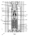
- the device illustrated produces pressure pulses in PFD medium flowing through a tubular drill collar or PIM and an upper annular drill collar flow channel.
- the flow guide is secured to the inner diameter of the drill collar/PIM.
- the centralizer secures the lower portion of the pulse generating device and is comprised of a non-magnetic, rigid, wear resistant material with outer flow channels.
- the pulser assembly provides essentially four outer flow channels that allow fluid or gas, such as drilling mud, or PFD medium to flow. These are defined as the upper annular, the middle annular, lower annular, and centralizer annular collar flow channels.
- the inner lower and inner middle flow channels direct the PFD medium flow to the pulser assembly within the PFD device.
- Annular flow of the PFD medium, by the flow guide and flow throttling device (FTD) is essentially laminar, and pulse signals are generated that are more detectable. Incorporation of a method and system of magnetic coupling, a concentrically located turbine, inductive coil for electrical power generation, double rolling bellows design and reduced pressure differential, collectively significantly reduce battery energy consumption when compared with conventional PFD devices.
- the PFD device utilizes a turbine residing near and within the proximity of a flow diverter.
- the flow diverter diverts PFD medium in an annular drill collar flow channel into and away from the turbine blades such that the force of the PFD medium causes the turbine blades and turbine to rotationally spin around an induction coil.
- the induction coil generates electrical power for operating the motor and other instrumentation mentioned previously.
- the motor is connected to the pilot actuator assembly via a drive shaft.
- the pilot actuator assembly comprises a magnetic coupling and pilot assembly.
- the magnetic coupling comprises outer magnets placed in direct relation to inner magnets located within the magnetic pressure cup or magnetic coupling bulkhead. The magnetic coupling translates the rotational motion of the motor, via the outer magnets to linear motion of the inner magnets via magnetic polar interaction.
- the linear motion of the inner magnets moves the pilot assembly, comprising the pilot shaft, and pilot valve, linearly moving the pilot into the pilot seat.
- This action allows for closing the pilot seat, pressurizing the flow throttling device (FTD), closing the flow throttling device (FTD) orifice, thereby generating a pressure pulse.
- Further rotation of the motor and drive shaft, via the magnetic coupling, moves the pilot assembly and pilot away from the pilot seat, depressurizing the flow throttling device (FTD) pressure chamber and opening the flow throttling device (FTD) and completing the pressure pulse.
- Identical operation of the pilot into and out of the pilot seat orifice can also be accomplished via linear to linear and also rotation to rotation motions of the outer magnets in relation to the inner magnets such that, for example, rotating the outer magnet to rotate the inner magnet to rotate a (rotating) pilot valve causing changes in the pilot pressure, thereby pushing the FTD (flow throttling device) up or down.
- Unique features of the pulser include the combination of middle and lower annular drill collar flow channels, flow throttling device (FTD), double rolling bellows, and pilot and lower flow connecting channels possessing angled outlet openings that helps create signals during transitioning from both the sealed (closed) and unsealed (open) positions. Additional unique features include a flow guide for transitional flow and a flow throttling device (FTD) pressure chamber designed to allow for generation of the pressure pulses. The flow throttling device (FTD) slides axially on a pulser guide pole being pushed by the pressure generated in the flow throttling device (FTD) pressure chamber when the pilot is in the seated position.
- FTD flow throttling device
- Increased bit rate is generated by allowing the PFD medium to quickly back flow through the unique connecting channel openings when the pilot is in the open position.
- Bi-directional axial movement of the poppet assembly is generated by rotating the motor causing magnets to convert the rotational motion to linear motion which opens and closes the pilot valve.
- rotary-rotary, rotary-linear, and linear-linear interaction of magnets with the poppet valve of the flow throttling device (FTD) are all acceptable and possible modes of moving the pulser in a bi-directional manner.
- Pulses of identical magnitude and frequency may be transmitted because the pulse is developed in near-laminar flow within the uniquely designed flow channels and a repeatable water hammer effect occurs due to the small amount of time required to close the flow throttling device (FTD).
- FTD flow throttling device
- the method for generating pressure pulses in a PFD medium flowing downward within a drill string or PIM in a region above or below the drill bit/PIM and/or the positive displacement motor or rotary steerable tool includes starting at an initial first position wherein a pilot (that can seat within a pilot seat which resides at the bottom of the middle annular drill collar flow channel) within a lower annular drill collar flow channel is not initially engaged with the pilot seat. The pilot is held in this position with the magnetic coupling. The next step involves rotating the motor causing the magnetic fields of the outer and inner magnets to move the pilot actuator assembly thereby moving the pilot into an engaged position with the pilot seat.
- This motion seals a lower annular drill collar flow channel from the middle annular drill collar flow channel and forces the inner PFD medium into a pair of upper connecting flow channels, expanding the flow throttling device (FTD) pressure chamber, causing a flow throttling device (FTD) to move up toward a middle annular drill collar flow channel and stopping before the orifice seat, thereby causing a flow restriction.
- the flow restriction causes a pressure pulse or pressure increase transmitted uphole.
- PFD medium remains in the exterior of the lower connecting flow channels, thus reducing the pressure drop across the pilot seat. This allows for minimal force requirements for holding the pilot in the closed position.
- the pilot moves back to the original or first position away from the pilot orifice while allowing fluid to flow through the second set of lower connecting flow channels within the lower annular drill collar flow channel.
- the flow throttling device (FTD) moves in a downward direction along the same direction as the flowing PFD medium until it is motionless. This decreases the FTD created pressure restriction of the main PFD medium flow past the flow throttling device (FTD) orifice completing the pulse.
- Controlling the pulse near the drill bit is essential to the operation of the present device.
- By developing and/or controlling the pulse it is possible to prevent, avoid, or eliminate “stick-slip” in many deviated or horizontal wells and placement of this amplification pulser with regard to the positive displacement motor or other similar device will likely determine the success rate of employing the PFD.
- Optimizing the pressure pulses' amplitudes and frequencies will also enhance the ROP (rate of penetration) in vertical sections along with increase the directional accuracy and aid in drilling a more vertical well, of so desired. It will also allow for an increased horizontal and vertical depth due to the increased ROP and ability to remove cutting and apply WOB (weight on the bit) in the deeper wells due to its snake-like action.
- An alternative embodiment for this PFD assembly unit includes connecting the motor to a drive shaft through a mechanical device such as a worm gear, barrel cam face cam or other mechanical means for converting the rotational motion of the motor into linear motion to propel the pilot actuator assembly.
- a mechanical device such as a worm gear, barrel cam face cam or other mechanical means for converting the rotational motion of the motor into linear motion to propel the pilot actuator assembly.
- An electronic circuit package can be used to control the motion and frequency of opening and closing the flow throttling device (FTD).
- FTD flow throttling device
- Yet another embodiment of the this PFD assembly unit includes a device which includes a pulser housing or bell with ports or channels through the housing or bell itself to allow for pilot flow exhaust adding another feature which assists in ensuring that pulsing continues if other flow channels become clogged during operation.
- the use of hydraulics together with an anti-magnetic polar interaction is used to drive the flow throttling device (FTD) such that magnets are located both within an extended and elongated pulser bell housing and as part of the magnet coupling assembly that is initially located below the flow throttling device (FTD).
- FTD flow throttling device
- the anti-magnetic forces (caused by N-S pole alignments) push the pulser bell/flow throttling device (FTD) assembly toward either an opened or closed position.
- the magnetic forces are always pushing against each other which allows for more regulated movement of the bell and FTD and helps ensure that there is little or no “sticking” of the position of the bell or poppet in the “dead center” position.
- a rotational poppet is utilized, similar or identical to that used with the prior inventors' MWD tool.
- This poppet activates the flow throttling device (FTD) so that pulses are created.
- the flow is diverted directly to the turbine which rotates the turbine blades (similar in design to the MWD turbine blades) at different or variable speeds depending on channel dimensions as well as the design of the turbine blades themselves. It has been determined that blades with small degree angles may turn slowly enough so that control of the motion of FTD is possible without the use of gears. For example, a high torque provided by the flow to the turbine could lead to a low spin speed of the blade, thereby allowing the operator freedom to choose pulse frequency and amplitude/magnitude. Pulse amplitude and rate is vitally important to drilling straight holes, drilling speeds, drilling lengths or fracturing of the formation(s). Additionally, separate flow channels can be used as a failsafe mechanism to allow flow to by-pass the FTD.
- FTD flow throttling device
- a more conventional telescoping hammer “sub” drill arrangement can be employed in that the flow throttling device (FTD) and remainder of the PFD described in the first apparatus above is located in special location with the drill collar.
- the location allows for telescoping of the collar, such that the collar provides a pistoning effect as pulsing occurs.
- FTD flow throttling device
- the pressure above the drill collar increases. This increased pressure expands the hammer “sub” drill arrangement.
- a gamma ray sensor together with any of the aforementioned designs will enhance the ability to keep the drilling rig and bit within the “payzone” for extended times.
- the use of these designs with or without a drill bit can be extended to determining more information regarding the oil/gas formation by measuring the magnitude of the pulses at distances remote from the downhole bore location.
- Sensors which may be placed at different locations away from the drilling site i.e. in nearby boreholes or several locations on the surface could be used to triangulate the exact location of the drill bit based on transit times in formations, indicate formation types due to pulse magnitude and propagation dampening, location of fractures in real time relative to the bit for directing while drilling, travel distance and velocities as required by the operation.
- FIG. 1 the device illustrated produces pressure pulses in drilling fluid flowing through a tubular drill collar and upper annular drill collar flow channel.
- the flow guide is secured to the inner diameter of the drill collar/PIM.
- the centralizer secures the lower portion of the pulse generating device and is comprised of a non-magnetic, rigid, wear resistant material with outer flow channels.
- the pilot In the open position the pilot is not engaged within the pilot seat allowing flow through the pilot seat. In the open position, fluid flows past the fishing head through the mud screen where a portion of the fluid flows through the pilot assembly. Fluid within the fishing head assembly flows through the upper orifice between the fishing head inner screen and the guide pole channel to allow for flow within the guide pole channel in the center of the pulser guide pole.
- pilot actuator assembly moves the pilot until it is in closed position with the pilot seat where no flow through can occur.
- the pilot actuator assembly is the only portion of the shaft that moves the pilot in a translational or rotational direction.
- the pilot orifice and pilot seat must be related to ensure hydraulic pressure differential which allows proper movement of the flow throttling device (FTD).
- the lower annular drill collar flow channel and the lower flow connecting channels are effectively sealed from the pilot channel so that their fluid flow is completely restricted from the interior of the FTD.
- fluid still enters the guide pole channel via the connecting channel, thus almost equalizing the pressure across the pilot assembly.
- the downward flow through the drill collar causes the fluid to flow past the fishing head and mud screen assembly.
- Fluid then flows into the middle guide pole channel through the pilot connecting channels and into the flow throttling device (FTD) pressure chamber filling and expanding the flow throttling device (FTD) pressure chamber, causing the flow throttling device (FTD) to rise along the pulser guide pole.
- FTD flow throttling device
- FTD flow throttling device
- FTD flow throttling device
- the signal provided in conventional technology is by a pulse that can be received up hole by use of a pressure transducer that is able to differentiate pressure pulses (generated downhole). These uphole pulses are then converted into useful signals providing information for the oilfield operator, such as gamma ray counts per second, azimuth, etc.
- Another advantage of the present disclosure is the ability to create a clean (essentially free of noise) pulse signal that is essentially independent of the fluid flow rate or pressure within the drill collar.
- the present invention thereby allows for pulses of varying amplitudes (in pressure) and frequencies to increase the bit rate. Addition of more than one pulser assemblies would lead to an exponential increase in the data bit rate received uphole.
- the connecting flow channels allow for equalization of the pressure drop across the pilot to be matched by the flow throttling device (FTD) as a servo-amplifier.
- the primary pressure change occurs between the inner middle and inner lower flow channels providing a pressure drop created by the flow throttling device (FTD) restricting the annular flow through the throttle zone.
- the pressure drop across the pilot is the only force per unit area that must be overcome to engage or disengage the pilot from the seated position and effect a pulse. This pressure drop across a minimal cross-sectional area of the pilot ensures that only a small force is required to provide a pulse in the larger flow area of the FTD.
- Magnetic coupling alleviates the concern for a rotary seal or bellow type seal which other MWD tools possess and it is noted that such seals have caused flooding and maintenance issues.
- FIG. 1 is an overview of an MWD
- FIG. 2A is a cut-away longitudinal sectional view of the fishing head assembly.
- FIG. 2B is a continuation of the cross-sectional view shown in FIG. 2A and includes details of the pulser, turbine, coil and motor assemblies.
- FIG. 2C is a continuation of FIG. 2B , illustrating more of the MWD components, particularly the various instrumentation, starting with the motor assembly through the gamma ray chassis end plug.
- FIG. 2D shows the final section of the MWD device.
- FIG. 3 describes the pulser system operation.
- FIG. 4 describes the operation of the magnetic coupling and how the pilot is actuated.
- FIG. 5 describes the double rolling bellows operation.
- FIG. 6 describes the guide pole channel and orifice chamber.
- FIG. 7 describes a cross section of a downhole pulse generating device in the open position.
- FIG. 8 describes a downhole pulse generating device powered by a positive displacement motor or turbine with a rotating valve flow bevel.
- FIG. 9 describes a downhole pulse generating device with an alternate valving for filling the pressure chambers.
- FIG. 10 describes a downhole pulse generating device where the inner and outer magnets are contained within the flow throttling device (FTD).
- FTD flow throttling device
- FIG. 11 describes a downhole pulse generating device where the flow through, a drill string adapter, and alternative measurement while drilling device allows for annular drill collar flow that is directed to the drilling bit to aid in clearing debris from the drill head.
- MWD Measurement-While-Drilling
- the device illustrated produces pressure pulses in drilling fluid flowing through a tubular drill collar [ 29 ] and an upper annular drill collar flow channel [ 2 ].
- the flow guide [ 23480 ] is secured to the inner diameter of the drill collar [ 29 ].
- the centralizer [ 36 ] secures the lower portion of the MWD device [ 100 ] and is comprised of a non-magnetic, rigid, wear resistant material with outer flow channels.
- Major assemblies of the MWD device [ 100 ] are shown as the fishing head assembly [ 15000 ], flow throttling device (FTD) and pulser actuator assembly complete the pulser assembly [ 170 ], turbine [ 110 ] and coil assembly [ 125 ], motor [ 130 ], various instrumentation [ 160 ], battery [ 71500 ], and stinger [ 87010 ].
- FTD flow throttling device
- FIG. 2A details the open position; drilling mud [ 115 ] flows past the fishing head assembly [ 15000 ] and fishing head outer screen [ 15020 ] where a portion of the drilling mud [ 115 ] flows through the fishing head inner screen [ 15030 ].
- Drilling mud [ 115 ] within the fishing head assembly [ 15000 ] flows through the upper orifice [ 26020 ] between the fishing head inner screen [ 15030 ] and the guide pole channel [ 175 ] to allow for flow within the guide pole channel [ 175 ] in the center of the pulser guide pole [ 26010 ].
- the present invention allows for several sized flow throttling devices ( FIG. 1 ) to be placed in a drilling collar, thereby allowing for various pressure pulse amplitudes and/or frequencies and consequential exponential increases in the data rate.
- FIG. 2B describes the MWD device [ 100 ] which utilizes a turbine [ 100 ] residing near and within proximity of a flow diverter [ 38013 ].
- the flow diverter [ 38013 ] diverts drilling mud [ 115 ] in an lower annular drill collar flow channel [ 120 ] into and away from the turbine blade [ 38230 ] such that the force of the drilling mud [ 115 ] causes the turbine blade [ 38230 ] and turbine assembly [ 110 ] to rotationally spin around a coil assembly [ 125 ].
- the coil assembly [ 125 ] generates electrical power for operating the motor [ 130 ] and various instrumentation [ 160 ] ( FIG. 1 ).
- the motor [ 130 ] comprises a worm gear [ 26920 ] or transmission system with fixed or adjustable gear ratios, a drive shaft [ 26910 ] centrally located between the motor [ 130 ] and the outer magnets [ 26510 ] and mechanically coupled to both.
- Located in a position external to the magnetic pressure cup [ 26210 ] are outer magnets [ 26510 ] placed in relation to inner magnets [ 26410 ] located in a position inside the magnetic pressure cup [ 26210 ] forming a magnetic coupling.
- the coupling is for translating the rotational motion of the motor [ 130 ], and outer magnets [ 26510 ] to linear motion for the inner magnets [ 26410 ] via a magnetic polar interaction.
- the linear motion of the inner magnets [ 26410 ] help move the pilot actuator assembly [ 135 ], comprised of the rear pilot shaft [ 26240 ], front pilot shaft [ 26230 ] and pilot [ 26220 ], linearly moving the pilot [ 26220 ] into the pilot seat [ 140 ] closing the pilot seat orifice [ 145 ] lifting the flow throttling device (FTD) [ 26150 ] into the flow throttling device (FTD) orifice [ 150 ] thereby generating a pressure pulse.
- a pilot valve [ 26225 ] is comprised of the pilot [ 26220 ], the pilot seat [ 140 ] and the pilot seat orifice [ 145 ].
- a pulse in the drilling mud [ 115 ] is sensed by the uphole system comprised of a pressure transducer and/or other sound wave receivers and communicated, optionally with wireless devices, to a computer [ 165 ](not shown) for interpretation and data reception and storage.
- FIG. 2B shows the turbine [ 110 ] which resides within the lower annular drill collar flow channel [ 120 ] of the flow guide [ 23480 ].
- the lower annular drill collar flow channel [ 120 ] may have special flow diverters [ 38013 ] that direct the flow of the drilling mud [ 115 ] through and around the surface of the turbine [ 110 ].
- the flow diverters [ 38013 ] project from the flow guide extension [ 26710 ] in a fashion so as to direct the flow of the drilling mud [ 115 ] to move the turbine blade [ 38230 ] and attached turbine assembly [ 110 ] thereby changing the linear motion of the drilling mud [ 115 ] into rotational motion of the turbine assembly [ 110 ].
- the turbine shroud [ 38310 ] contains magnets [ 155 ] that rotate with the motion of the turbine [ 110 ] around a coil assembly [ 125 ] causing electrical power to be generated for the operation of the motor [ 130 ].
- the outside diameter of the turbine blade [ 38230 ] is smaller than the flow guide extension [ 26710 ] inner diameter, thereby allowing the turbine [ 110 ] to be removed concurrently with the pulser housing [ 26810 ] from the MWD device [ 100 ].
- the configuration of the turbine blade [ 38230 ] and flow diverter [ 38013 ] may be of various angles depending on the drilling conditions and needs of the pulsation rate (frequency) and magnitude (amplitude) for the downhole pulser.
- the electrical power is used for operation of various instrumentation [ 160 ] ( FIG. 1 ) such as accelerometers, photo-multiplier tubes (PMT), crystal gamma ray scintillators and other useful instrumentation sensors and processors.
- instrumentation such as accelerometers, photo-multiplier tubes (PMT), crystal gamma ray scintillators and other useful instrumentation sensors and processors.
- Excess power provides charging for the battery [ 71500 ] ( FIG. 1 ) for storage and use under certain conditions where the coil assembly [ 125 ] does not generate enough power to operate the MWD device [ 100 ] under no flow conditions.
- the velocity and consistency of the drilling mud [ 115 ] traveling through the lower annular drill collar flow channel [ 120 ] may vary due to wellbore conditions generally providing varying forces on the turbine [ 110 ].
- the varying forces cause the turbine [ 110 ] to spin at different velocities exhibiting a wide range of power to be developed by the coil assembly [ 125 ]. Fluctuations in the power are regulated through an electrical regulation circuit.
- the motor [ 130 ] receives a signal from a computer [ 165 ] (not shown) that is onboard the MWD device [ 100 ] to move the drive shaft [ 26910 ].
- the motor [ 130 ] may be synchronous, asynchronous, or stepper and is activated to fully rotate or to rotationally increment various degrees, depending on the wellbore conditions or the observed signal intensity and/or duration.
- FIG. 2C shows the section of the MWD device [ 100 ] containing various instrumentation [ 160 ], starting with the motor [ 130 ].
- Standard instrumentation known to those skilled in the art, may include but are not limited to accelerometers, photo-multiplier tubes (PMT), crystal gamma ray scintillators and other useful instrumentation needed for monitoring drilling, fracing, formations, pressures, and/or temperatures.
- PMT photo-multiplier tubes
- crystal gamma ray scintillators and other useful instrumentation needed for monitoring drilling, fracing, formations, pressures, and/or temperatures.
- FIG. 2D illustrates the final bottom section of the MWD device [ 100 ] including the battery [ 71500 ], the stinger [ 87010 ] and the stinger nose [ 87020 ].
- the linear motion of the flow throttling device (FTD) [ 26150 ] axially along the pulser guide pole [ 26010 ] is both up and down (along a bi-axial direction).
- FIG. 3 shows the pulser assembly [ 170 ] within a drill collar [ 29 ] when in the closed position the pilot actuator assembly [ 135 ] moves the pilot [ 26220 ] until it is in closed position with the pilot seat [ 140 ] where no flow through can occur.
- the front pilot shaft [ 26230 ] is the only portion of the pilot actuator assembly [ 135 ] that moves the pilot [ 26220 ] in a translational or rotational direction.
- the pulser assembly [ 170 ] comprising a pulser housing [ 26810 ] of a non-magnetic material, and a magnetic pressure cup [ 26210 ], which is also comprised of a non-magnetic material, and encompassed by the outer magnets [ 26510 ].
- the outer magnets [ 26510 ] may comprise several magnets, or one or more components of magnetic or ceramic material exhibiting several magnetic poles within a single component. Additionally the magnetic pole positions may be customizable, depending on the drilling conditions, to achieve a clear pressure signal.
- the outer magnets [ 26510 ] are housed in an outer magnet housing [ 26515 ] that is attached to the drive shaft [ 26910 ].
- the inner magnet assembly that contains the pilot actuator assembly [ 135 ] comprised of the rear pilot shaft [ 26240 ] linearly engaged in a front pilot shaft [ 26230 ], which is moved longitudinally in the center of the pulser assembly [ 170 ].
- the rear pilot shaft [ 26240 ] also comprised of non-magnetic material.
- the outer magnets [ 26510 ] and the inner magnets [ 26410 ] are placed so that the magnetic polar regions interact, attracting and repelling as the outer magnets [ 26510 ] are moved about the inner magnets [ 26410 ].
- Using the relational combination of magnetic poles of the moving outer magnets [ 26510 ] and inner magnets [ 26410 ], causes the inner magnets [ 26410 ] with the rear pilot shaft [ 26240 ], to move the pilot actuator assembly [ 135 ] linearly and interactively as a magnetic field coupling.
- the linear motion is along the rear pilot shaft [ 26240 ], through the front pilot shaft [ 26230 ], the double rolling bellows [ 26310 ] and to the pilot [ 26220 ] thereby opening or closing the passage between the pilot [ 26220 ] and the pilot seat [ 140 ].
- the use of outer magnets [ 26510 ] and inner magnets [ 26410 ] to provide movement from rotational motion to linear motion also allows the motor [ 130 ] ( FIG. 2B ) to be located in an air atmospheric environment in lieu of the use of a lubricating fluid [ 180 ] environment inside the magnetic pressure cup [ 26210 ]. This also allows for a decrease in the cost of the motor [ 130 ] ( FIG.
- Switching fields between the outer magnets [ 26510 ] and the inner magnets [ 26410 ] provides a magnetic spring like action that allows for pressure relief by moving the pilot [ 26220 ] away from the pilot seat [ 140 ] thereby regulating the pulse magnitude. Additionally the outer magnets [ 26510 ], operate in the lower pressure of the pulser housing [ 26810 ] as opposed to the higher pressure within the magnetic pressure cup [ 26210 ], allowing for a greatly reduced need in the amount of energy required by the motor to longitudinally move the pilot actuator assembly [ 135 ].
- the front pilot shaft [ 26230 ] passes through the anti-rotation block [ 26350 ] located below the double rolling bellows [ 26310 ].
- the anti-rotation block [ 26350 ] located near the double rolling bellows is secured to the inside of the magnetic pressure cup [ 26210 ] and restricts the rotational movement of the front pilot shaft [ 26230 ].
- an embodiment of the double rolling bellows [ 26310 ] includes sealing a portion of the surface of the front pilot shaft [ 26230 ] engaged around a pilot shaft land [ 26351 ] and the interior of the hollow magnetic pressure cup [ 26210 ]. Sealing of the double rolling bellows [ 26310 ] keeps drilling mud [ 115 ] from entering the bellows chamber [ 185 ] and intermingling with the inner magnet chamber lubricating fluid [ 180 ] when the pilot [ 26220 ] is moved to an open position off the pilot seat [ 140 ]. Another embodiment is to allow the double rolling bellows [ 26310 ] to move linearly, concurrent with the front pilot shaft [ 26230 ].
- the design of the double rolling bellows [ 26310 ] interacting with the front pilot shaft [ 26230 ] and the bellows chamber [ 185 ] allow the double rolling bellows [ 26310 ] to conform to the space constraints of the bellows chamber [ 185 ] providing flexible sealing without the double rolling bellows [ 26310 ] being displaced by the drilling mud [ 115 ]. It was also found that the double loop [ 190 ] configuration of the double rolling bellows [ 26310 ] consumes much less energy than previous designs thereby reducing the overall consumption of energy. Energy consumption is also reduced by pre-filling the bellows chamber [ 185 ] with appropriate lubricating fluid [ 180 ]. This allows for reduction of the pressure differential on both sides of the double rolling bellows [ 26310 ].
- the smaller pressure differential enhances performance by the double rolling bellows [ 26310 ] and minimizes wear and energy consumption.
- the lubricating fluid [ 180 ] may be petroleum, synthetic or bio-based and should exhibit compression characteristics similar to hydraulic fluid.
- the double loop [ 190 ] configuration of the double rolling bellows is designed to minimize energy consumption.
- FIG. 6 shows another embodiment of the present disclosure pertaining to the configuration of the guide pole channel [ 175 ] and orifice chamber [ 200 ] in the proximity of the pilot seat [ 140 ] and pilot seat orifice [ 145 ].
- the flow throttling device (FTD) [ 26150 ] moves toward the flow throttling device (FTD) seat [ 210 ].
- the flow throttling device (FTD) [ 26150 ] withdraws from the flow throttling device (FTD) seat [ 210 ].
- the pressure differential between the drilling mud [ 115 ] pressure and the orifice chamber [ 200 ] moves the flow throttling device (FTD) [ 26150 ] more rapidly, enabling a very forceful restriction of the flow throttling device (FTD) orifice [ 150 ] and a very defined pulse and therefore clearer signals which are more easily interpreted.
- FTD flow throttling device
- FIG. 7 is an alternate view of cross-section of a pulsing/fracturing/drilling (PFD) device [ 101 ] showing the PFD device [ 101 ] without a drill collar [ 29 ].
- the pulsing/fracturing/drilling (PFD) medium [ 116 ] flows into the upper annular drill collar flow channel [ 2 ] located inside the flow guide [ 23480 ] which may be integral to the collar [ 29 ].
- a pulser guide pole [ 26010 ] Internal to the flow guide [ 23480 ] is a pulser guide pole [ 26010 ] which allows the flow throttling device (FTD) [ 26150 ] to move axially along the pulser guide pole [ 26010 ] where the flow throttling device (FTD) [ 26150 ] will contact the flow throttling device (FTD) seat [ 210 ] thereby sealing off the outer annular drill collar flow channels [ 215 ].
- the flow guide seal [ 220 ] keeps or PFD medium [ 116 ] from flowing around the flow guide [ 23480 ] thereby ensuring that the PFD medium [ 116 ] only flows through the outer annular drill collar flow channels [ 215 ] and through the guide pole channel [ 175 ].
- FIG. 7 shows the flow throttling device (FTD) [ 26150 ] in the open position and the pilot [ 23220 ] in the closed position sitting within the pilot seat [ 140 ], where the flow throttling device (FTD) [ 26150 ] is away from the flow throttling device (FTD) seat [ 210 ] allowing the flow throttling device (FTD) pressure chamber [ 225 ] to fill with or PFD medium [ 116 ] through the pilot connecting channel [ 230 ] via the guide pole channel [ 175 ].
- FTD flow throttling device
- the flow throttling device (FTD) [ 26150 ] moves up within the flow guide [ 23480 ] due to hydraulic pressure caused by the or PFD medium [ 116 ] exerting a hydraulic force acting on the flow throttling device (FTD) [ 26150 ] in the flow throttling device (FTD) pressure chamber [ 225 ].
- the force acts to push the flow throttling device (FTD) [ 26150 ] up within the flow guide [ 23480 ] and subsequently moves the outer magnets [ 26510 ] in the same direction.
- the outer magnets [ 26510 ] continue to move up and subsequently the opposing magnetic fields of the outer magnets [ 26510 ] pass the center of the magnetic fields of the inner magnets [ 26410 ].
- the inner magnets [ 26410 ] attached to the pilot [ 23220 ] then, due to the magnetic fields, move in the opposite direction as the outer magnets [ 26510 ] cause the pilot [ 23220 ] to move down, in the same direction as the inner magnets [ 26410 ], thereby moving the pilot [ 23220 ] off the pilot seat [ 140 ].
- Movement of the pilot [ 23220 ] off the pilot seat [ 140 ] allows or PFD medium [ 116 ] to flow through the pilot exhaust channels [ 235 ] into the lower annular drill collar flow channel [ 120 ] thereby relieving pressure in the flow throttling device (FTD) pressure chamber [ 225 ]. Release of this pressure causes the flow throttling device (FTD) [ 26150 ] to reverse direction away from the flow throttling device (FTD) seat [ 210 ].
- FTD flow throttling device
- the outer magnets [ 26510 ] move downward thereby moving past the center of the magnetic fields of the inner magnets [ 26410 ] subsequently causing the inner magnets [ 26410 ] to move in an upward direction, again due to opposing magnetic fields.
- the upward movement of the inner magnets [ 26410 ] moves the pilot [ 23220 ] into the pilot seat [ 140 ] causing the flow throttling device (FTD) pressure chamber [ 225 ] to refill to repeat the aforementioned cycle.
- the outer magnets [ 26510 ] are stacked in position such that the fields are in opposition to each other. For example the stack top magnetic end is “N” and the bottom end is “S”. Moving down to the next magnet the field is “S” on the top and “N” on the bottom. Repeating the first sequence, the top end is “N” and the bottom end is “S”.
- the inner magnets [ 26410 ] fields are stacked similarly.
- the movement of the similar magnetic fields of the outer magnets [ 26510 ] to the inner magnets [ 26410 ] causes repulsion of the flow throttling device (FTD) [ 26150 ] and the pilot [ 23220 ] basically holding the pilot [ 23220 ] in position until the outer magnet passes the center field of the opposing inner magnet [ 26410 ] which is an opposite pole and therefore repelled by the outer magnet [ 26510 ] causing the inner magnet [ 26410 ] to move in the opposite direction as the outer magnet [ 26510 ].
- FTD flow throttling device
- the pilot [ 23220 ] is attached to the inner magnets [ 26410 ] and through a double rolling bellows [ 26310 ] which resides in a bellows chamber [ 185 ].
- the bellows chamber [ 185 ] is filled with a viscous liquid and also acts as a dampening source for the pilot [ 23220 ].
- FIG. 8 shows a cross section of a pulsing/fracturing/drilling (PFD) device [ 101 ] without the drill collar [ 29 ] where the (fluid or gas) PFD medium [ 116 ] (the dashed arrows indicate direction of flow) flows into the flow guide [ 23480 ] and into the upper annular drill collar flow channel [ 2 ] and also into the pulser guide pole [ 26010 ] in the pilot flow channel [ 175 ].
- PFD pulsing/fracturing/drilling
- the flow throttling device (FTD) [ 26150 ] is in the open position the PFD medium [ 116 ] flows unrestricted around the flow throttling device (FTD) [ 26150 ] to the bypass flow regulator [ 255 ].
- PFD medium [ 116 ] from the bypass flow regulator [ 255 ] continues through the turbine blades [ 38230 ] thus rotating the rotating motor [ 250 ] and the rotating pilot valve [ 245 ].
- Linear movement of the flow throttling device (FTD) [ 26150 ] is caused by the PFD medium [ 116 ] that is moving through the pulser guide pole [ 26010 ] in the guide pole channel [ 175 ] and exiting into the flow throttling device (FTD) pressure chamber [ 225 ] above the rotating pilot valve [ 245 ].
- the rotating pilot valve [ 245 ] includes a feature noted as the rotating valve flow bevel [ 280 ] and is coupled to a rotating motor [ 250 ].
- the rotating motor [ 250 ] provides rotational motion to the rotating pilot valve [ 245 ].
- the upper portion of the rotating pilot valve [ 245 ] resides at the bottom of the pulser guide pole [ 26010 ] and, upon rotation, allows the rotating valve flow bevel [ 280 ] to seal and unseal the guide pole exit channel [ 26011 ].
- the rotating motor [ 250 ] rotates the rotating pilot valve [ 245 ] such that the rotating valve flow bevel [ 280 ] passes the guide pole exit channel [ 26011 ] allowing for the PFD medium [ 116 ] in the flow throttling device (FTD) pressure chamber [ 225 ] to evacuate, thereby reducing the hydraulic pressure acting on the flow throttling device (FTD) [ 26150 ] and allowing the flow throttling device (FTD) [ 26150 ] to move downward on the pulser guide pole [ 26010 ] unsealing the outer annular drill collar flow channels [ 215 ].
- FDD flow throttling device
- FIG. 9 shows a cross section of a PFD device [ 101 ] in a drill collar [ 29 ] where the PFD medium [ 116 ] (the dashed arrows indicate direction of flow) flows into the flow guide [ 23480 ] into the upper annular drill collar flow channel [ 2 ] and also into the pulser guide pole [ 26010 ] in the guide pole channel [ 175 ].
- the PFD medium [ 116 ] from the upper annular drill collar flow channel [ 2 ] flows through the outer annular drill collar flow channels [ 215 ] when the flow throttling device (FTD) [ 26150 ] is in the open position and not in contact with the flow throttling device (FTD) seat [ 210 ].
- FTD flow throttling device
- the PFD medium [ 116 ] flows unrestricted around the flow throttling device (FTD) [ 26150 ] to the bypass flow regulator [ 255 ].
- PFD medium [ 116 ] from the bypass flow regulator [ 255 ] continues moving down the outer annular drill collar flow channels [ 215 ] where it contacts the turbine blade [ 38230 ] causing the turbine blade [ 38230 ] to rotate the rotating motor [ 250 ].
- the linear motion of the PFD medium [ 116 ] is converted into rotational motion at the rotating motor [ 250 ].
- the rotating motor [ 250 ] then rotates the rotating pilot valve [ 245 ] within the flow throttling device (FTD) [ 26150 ].
- the rotating pilot valve [ 245 ] has a top angled cutout [ 260 ] and a bottom angled cutout [ 265 ] that are located at the top-most portion of the rotating pilot valve [ 245 ] within the lower end of the pulser guide pole [ 26010 ].
- the top angled cutout [ 260 ] passes by the chamber inlet channel [ 270 ] thus sealing off any PFD medium [ 116 ] flow into the flow throttling device (FTD) pressure chamber [ 225 ].
- FTD flow throttling device
- the bottom angled cutout [ 265 ] then coincides with the chamber exhaust channel [ 275 ] allowing the evacuation of PFD medium [ 116 ] from the flow throttling device (FTD) pressure chamber [ 225 ] and causing the flow throttling device (FTD) [ 26150 ] to move away from the flow throttling device (FTD) seat [ 210 ] and allowing PFD medium [ 116 ] to flow again through the outer annular drill collar flow channels [ 215 ].
- the movement of the flow throttling device (FTD) [ 26150 ] against and away from the flow throttling device (FTD) seat [ 210 ] thereby opening and closing the outer annular drill collar flow channels [ 215 ] sends a pressure pulse through the PFD medium [ 116 ], causing cleansing of any drill bit that may be attached.
- the pulse causes an increased removal of cuttings from any sort of drilling operation, annular area, or drill bit teeth or jets and also assists in fracturing formations due to the high shear pressures caused in the sudden release (shock) of a tremendous volume PFD medium [ 116 ] or of any fluid/gas column.
- top angled cutout [ 260 ] and the bottom angled cutout [ 265 ] are continuously rotated as part of the rotating valve [ 245 ] any time the PFD medium [ 116 ] is being used. Passage of the top angled cutout [ 260 ] and the bottom angled cutout [ 265 ] by the chamber inlet channel [ 270 ] and the chamber exhaust channel [ 275 ] act to provide a constantly intermittent flow of PFD medium [ 116 ] through the flow throttling device (FTD) pressure chamber [ 225 ].
- FTD flow throttling device
- the rotational frequency of the top angled cutout [ 260 ] and the bottom angled cutout [ 265 ] by the chamber inlet channel [ 270 ] and the chamber exhaust channel [ 275 ] determine the pressure pulse duration and frequency. Rotational speeds (frequency) and pulse amplitudes (pressure pulse sizes) are variable, depending on the operator's settings and what is intended.
- the pulser guide pole [ 26010 ] allows for the chamber inlet channel [ 270 ] and the chamber exhaust channel [ 275 ] to be linearly offset so that the top angled cutout [ 260 ] never aligns with the chamber exhaust channel [ 275 ] and in parallel, the bottom angled cutout [ 265 ] never aligns with the chamber inlet channel [ 270 ].
- FIG. 10 is a cross section of a PFD device [ 101 ] without the drill collar [ 29 ] (not shown) where the PFD medium [ 116 ] (the dashed arrows indicate direction of flow) flows into the flow guide [ 23480 ] and into the upper annular drill collar flow channel [ 2 ] and also into the guide pole channel [ 175 ].
- the PFD medium [ 116 ] from the upper annular drill collar flow channel [ 2 ] flows through the outer annular drill collar flow channels [ 215 ] when the flow throttling device (FTD) [ 26150 ] is in the open position and not in contact with the flow throttling device (FTD) seat [ 210 ].
- FTD flow throttling device
- the flow throttling device (FTD) [ 26150 ] has, within and attached to it, outer magnet [ 26510 ] which is arranged in detail as explained in FIG. 7 .
- Inner magnets [ 26410 ] move axially along the pulser guide pole [ 26010 ] to open and close the pilot exhaust channels [ 235 ] and the pilot connecting channels [ 230 ] (shown if FIG. 7 ).
- the flow throttling device (FTD) [ 26150 ] moves up to closed position due to the hydraulic pressure within the flow throttling device (FTD) pressure chamber [ 225 ], the outer magnets [ 26510 ] attached to the flow throttling device (FTD) [ 26150 ] move with the flow throttling device (FTD) [ 26150 ] past the inner magnets [ 26410 ] causing the magnetic field of the outer magnets [ 26510 ] to repel the magnetic field of the inner magnets [ 26410 ] moving the inner magnets [ 26410 ] downward to open up the pilot exhaust channels [ 235 ] and closing off the pilot connecting channels [ 230 ] (shown in FIG. 7 ) decreasing the hydraulic pressure in the flow throttling device (FTD) pressure chamber [ 225 ] and allowing the flow throttling device (FTD) [ 26150 ] to move downward to open position and thus repeating the cycle.
- FTD flow throttling device
- the passing of the outer magnets [ 26510 ] causes the inner magnets [ 26410 ] to repel the inner magnets [ 26410 ] to move upward thereby sealing the flow throttling device (FTD) pressure chamber [ 225 ].
- the inner magnets [ 26410 ] open up the pilot exhaust channels [ 235 ] where pressure is relieved from the flow throttling device (FTD) pressure chamber [ 225 ] and the flow throttling device (FTD) [ 26150 ] is pushed down the pulser guide pole [ 26010 ].
- Movement of the flow throttling device (FTD) [ 26150 ] and outer magnets [ 26510 ] downward allows the outer magnets [ 26510 ] to travel past the inner magnets [ 26410 ], magnetically attracting the inner magnets [ 26410 ] off the openings for the flow throttling device (FTD) pressure chamber [ 225 ].
- the outer magnets [ 26510 ] move down to cover the pilot exhaust channels [ 235 ] opening up the pilot connecting channel [ 230 ] (shown in FIG. 7 ) to allow for filling of the flow throttling device (FTD) pressure chambers [ 225 ].
- the inner magnets [ 26410 ] act as valving to open and close the flow throttling device (FTD) pressure chamber [ 225 ] and the pilot connecting channel [ 230 ] (shown in FIG. 7 ).
- FIG. 11 provides a schematic for a drill string adapter [ 500 ] with an outer casing [ 510 ] with an upper pressure chamber [ 515 ] and a lower pressure chamber [ 520 ].
- the lower pressure chamber [ 520 ] has one or more vent channel [ 525 ] which allows for internal pressure to be equal to that of the annulus pressure.
- a drill bit adapter [ 530 ] is shaped such that a piston land [ 535 ] with a top land surface [ 540 ] and a bottom land surface [ 545 ] and land seal [ 550 ] are axially moveable and define a variable volume within the upper pressure chamber [ 515 ] and lower pressure chamber [ 520 ].
- the drill bit adapter [ 530 ] also has a centrally located adapter channel [ 555 ] through which PFD medium [ 116 ] flows to the drilling head [not shown].
- the lower pressure chamber [ 520 ] has an internal lower end spline [ 560 ] through which an external drill bit adapter spline [ 565 ] fits.
- the internal lower end spline [ 560 ] and external drill bit adapter spline [ 565 ] allow for axial movement of the drill bit adapter [ 530 ] independent of the drill string adapter [ 500 ].
- the intermeshing of the internal lower end spline [ 560 ] and the external drill bit adapter spline [ 565 ] interlock the drill string adapter [ 500 ] and the drill bit adapter [ 530 ] so that they move as a unit rotationally.
- the upper pressure chamber [ 515 ] contains an upper spring [ 570 ] which functions to provide a variable pressure on the top land surface [ 540 ] of the piston land [ 535 ] thereby transmitting that force through the piston land [ 535 ] to the drill bit adapter [ 530 ].
- the upper spring [ 570 ] compensates for variations in movement of the drill bit [not shown] and subsequently the drill bit adapter [ 530 ].
- the lower pressure chamber [ 520 ] includes a lower spring [ 575 ] which resides below the piston land [ 535 ] and the drill bit adapter [ 530 ] and contacts the bottom land surface [ 545 ].
- the lower spring [ 575 ] and the upper spring [ 570 ] act in opposing direction (inversely) to each other on the piston land [ 535 ], bottom land surface [ 545 ] and the top land surface [ 540 ] thereby dampening the axial motion of the drill bit adapter [ 530 ].
- this design may be a drill bit adapter vent [ 580 ] from the adapter channel [ 555 ] to the lower pressure chamber [ 520 ] for an MWD [ 100 ] or PFD device [ 101 ] such that the vent channel [ 525 ] may be capped or blocked.
- Installation of an MWD device [ 100 ] or PFD device [ 101 ] may be installed within the adapter channel [ 555 ].
Landscapes
- Engineering & Computer Science (AREA)
- Life Sciences & Earth Sciences (AREA)
- Geology (AREA)
- Mining & Mineral Resources (AREA)
- Physics & Mathematics (AREA)
- Environmental & Geological Engineering (AREA)
- Fluid Mechanics (AREA)
- General Life Sciences & Earth Sciences (AREA)
- Geochemistry & Mineralogy (AREA)
- Mechanical Engineering (AREA)
- Earth Drilling (AREA)
- Perforating, Stamping-Out Or Severing By Means Other Than Cutting (AREA)
Priority Applications (7)
| Application Number | Priority Date | Filing Date | Title |
|---|---|---|---|
| US12/004,121 US7836948B2 (en) | 2007-05-03 | 2007-12-20 | Flow hydraulic amplification for a pulsing, fracturing, and drilling (PFD) device |
| CA2710281A CA2710281C (en) | 2007-12-20 | 2008-12-17 | Pulse rate of penetration enhancement device and method |
| EP08864254.1A EP2235323B1 (en) | 2007-12-20 | 2008-12-17 | Pulse rate of penetration enhancement device and method |
| RU2010130254/03A RU2010130254A (ru) | 2007-12-20 | 2008-12-17 | Устройство и способ импульсного увеличения скорости проходки |
| MX2010006797A MX351601B (es) | 2007-12-20 | 2008-12-17 | Método y dispositivo de velocidad de penetración de impulso mejorado. |
| PCT/US2008/013804 WO2009082453A2 (en) | 2007-12-20 | 2008-12-17 | Pulse rate of penetration enhancement device and method |
| US12/316,864 US7958952B2 (en) | 2007-05-03 | 2008-12-17 | Pulse rate of penetration enhancement device and method |
Applications Claiming Priority (2)
| Application Number | Priority Date | Filing Date | Title |
|---|---|---|---|
| US92740007P | 2007-05-03 | 2007-05-03 | |
| US12/004,121 US7836948B2 (en) | 2007-05-03 | 2007-12-20 | Flow hydraulic amplification for a pulsing, fracturing, and drilling (PFD) device |
Related Child Applications (1)
| Application Number | Title | Priority Date | Filing Date |
|---|---|---|---|
| US12/316,864 Continuation-In-Part US7958952B2 (en) | 2007-05-03 | 2008-12-17 | Pulse rate of penetration enhancement device and method |
Publications (2)
| Publication Number | Publication Date |
|---|---|
| US20080271923A1 US20080271923A1 (en) | 2008-11-06 |
| US7836948B2 true US7836948B2 (en) | 2010-11-23 |
Family
ID=40801809
Family Applications (1)
| Application Number | Title | Priority Date | Filing Date |
|---|---|---|---|
| US12/004,121 Active 2028-05-27 US7836948B2 (en) | 2007-05-03 | 2007-12-20 | Flow hydraulic amplification for a pulsing, fracturing, and drilling (PFD) device |
Country Status (6)
| Country | Link |
|---|---|
| US (1) | US7836948B2 (es) |
| EP (1) | EP2235323B1 (es) |
| CA (1) | CA2710281C (es) |
| MX (1) | MX351601B (es) |
| RU (1) | RU2010130254A (es) |
| WO (1) | WO2009082453A2 (es) |
Cited By (16)
| Publication number | Priority date | Publication date | Assignee | Title |
|---|---|---|---|---|
| US20090057016A1 (en) * | 2005-11-21 | 2009-03-05 | Hall David R | Downhole Turbine |
| WO2012094318A1 (en) * | 2011-01-06 | 2012-07-12 | Benny Donald Mashburn | Fish-thru screen apparatus and method |
| WO2012106028A1 (en) * | 2011-02-03 | 2012-08-09 | Exxonmobill Upstream Research Company | Systems and methods for managing pressure in casing annuli of subterranean wells |
| US20130048300A1 (en) * | 2011-08-31 | 2013-02-28 | Teledrill, Inc. | Controlled Pressure Pulser For Coiled Tubing Applications |
| US8499857B2 (en) | 2007-09-06 | 2013-08-06 | Schlumberger Technology Corporation | Downhole jack assembly sensor |
| RU2511321C1 (ru) * | 2012-11-07 | 2014-04-10 | Федеральное государственное бюджетное образовательное учреждение высшего профессионального образования "Национальный исследовательский Томский политехнический университет" | Многоимпульсный источник для воздействия на стенки жидкозаполненных скважин |
| US9077616B2 (en) | 2012-08-08 | 2015-07-07 | International Business Machines Corporation | T-star interconnection network topology |
| US9222347B1 (en) | 2014-10-16 | 2015-12-29 | Gary C. Walls | Hydraulic fracturing system and method |
| US9222346B1 (en) | 2014-10-16 | 2015-12-29 | Gary C. Walls | Hydraulic fracturing system and method |
| RU2593842C1 (ru) * | 2012-11-30 | 2016-08-10 | Нэшнл Ойлвэл Варко, Л.П. | Скважинное устройство для создания пульсаций для выполнения внутрискважинных работ |
| US9453410B2 (en) | 2013-06-21 | 2016-09-27 | Evolution Engineering Inc. | Mud hammer |
| US9702204B2 (en) | 2014-04-17 | 2017-07-11 | Teledrill, Inc. | Controlled pressure pulser for coiled tubing measurement while drilling applications |
| RU2637678C1 (ru) * | 2016-07-06 | 2017-12-06 | Федеральное государственное унитарное научно-производственное предприятие "Геологоразведка" | Установка для бурения скважин |
| WO2018204644A1 (en) * | 2017-05-03 | 2018-11-08 | Coil Solutions, Inc. | Bit jet enhancement tool |
| CN109184655A (zh) * | 2018-11-21 | 2019-01-11 | 重庆地质矿产研究院 | 连续油管拖动带底部坐封式的脉冲水力压裂工具及方法 |
| US10633968B2 (en) | 2011-12-23 | 2020-04-28 | Teledrill, Inc. | Controlled pressure pulser for coiled tubing measurement while drilling applications |
Families Citing this family (33)
| Publication number | Priority date | Publication date | Assignee | Title |
|---|---|---|---|---|
| US9284780B2 (en) * | 2001-08-19 | 2016-03-15 | Smart Drilling And Completion, Inc. | Drilling apparatus |
| US7836948B2 (en) | 2007-05-03 | 2010-11-23 | Teledrill Inc. | Flow hydraulic amplification for a pulsing, fracturing, and drilling (PFD) device |
| US20090114396A1 (en) * | 2007-11-05 | 2009-05-07 | David John Kusko | Wellsite measurement and control while producing device |
| NO330266B1 (no) | 2009-05-27 | 2011-03-14 | Nbt As | Anordning som anvender trykktransienter for transport av fluider |
| US8261855B2 (en) | 2009-11-11 | 2012-09-11 | Flanders Electric, Ltd. | Methods and systems for drilling boreholes |
| GB201002854D0 (en) * | 2010-02-19 | 2010-04-07 | Wavefront Reservoir Technologies Ltd | Magnet - operated pulsing tool |
| SA111320531B1 (ar) | 2010-06-17 | 2014-08-04 | امباكت تيكنولوج& | طريقة تستخدم ضغوط انتقالية في عمليات استخلاص الهيدروكربون |
| US9562409B2 (en) | 2010-08-10 | 2017-02-07 | Baker Hughes Incorporated | Downhole fracture system and method |
| US8869885B2 (en) * | 2010-08-10 | 2014-10-28 | Baker Hughes Incorporated | Fluid metering tool with feedback arrangement and method |
| EP2694848B1 (en) | 2011-04-06 | 2020-03-11 | David John Kusko | Hydroelectric control valve for remote locations |
| US9309762B2 (en) | 2011-08-31 | 2016-04-12 | Teledrill, Inc. | Controlled full flow pressure pulser for measurement while drilling (MWD) device |
| US8714257B2 (en) * | 2011-09-22 | 2014-05-06 | Baker Hughes Incorporated | Pulse fracturing devices and methods |
| AR089304A1 (es) | 2011-12-19 | 2014-08-13 | Impact Technology Systems As | Metodo para recuperacion de presion por impacto |
| CN102536121B (zh) * | 2012-02-08 | 2013-12-18 | 中国石油大学(北京) | 脉冲式井下增压射流钻井方法及装置 |
| FI123928B (en) | 2012-09-06 | 2013-12-31 | Robit Rocktools Ltd | Method of drillhole exploration, drill arrangement, and drillhole exploration configuration |
| DK177771B1 (en) * | 2013-06-04 | 2014-06-23 | Yellow Shark Holding Aps | Agitator with oscillating weight element |
| US9528349B2 (en) * | 2013-09-25 | 2016-12-27 | Halliburton Energy Services, Inc. | Downhole power generation using a mud operated pulser |
| US9988889B2 (en) * | 2013-11-08 | 2018-06-05 | Rock Hill Propulsion, Inc. | Pneumatic system and process for fracturing rock in geological formations |
| US20190100994A1 (en) * | 2017-09-29 | 2019-04-04 | Teledrill, Inc. | Coiled Tubing Applications and Measurement Tool |
| US10392916B2 (en) | 2014-08-22 | 2019-08-27 | Baker Hughes, A Ge Company, Llc | System and method for using pressure pulses for fracture stimulation performance enhancement and evaluation |
| CA3013075A1 (en) | 2016-02-16 | 2017-08-24 | Extreme Rock Destruction LLC | Drilling machine |
| CN106368664B (zh) * | 2016-12-09 | 2022-09-06 | 长江大学 | 一种脉冲式压裂滑套 |
| US10890030B2 (en) * | 2016-12-28 | 2021-01-12 | Xr Lateral Llc | Method, apparatus by method, and apparatus of guidance positioning members for directional drilling |
| US11255136B2 (en) | 2016-12-28 | 2022-02-22 | Xr Lateral Llc | Bottom hole assemblies for directional drilling |
| CN106706047B (zh) * | 2017-01-10 | 2023-05-09 | 海默科技(集团)股份有限公司 | 一种基于Ba133的水下多相流量计 |
| WO2019014142A1 (en) | 2017-07-12 | 2019-01-17 | Extreme Rock Destruction, LLC | LATERALLY ORIENTED CUTTING STRUCTURES |
| CN109826576B (zh) * | 2019-03-15 | 2024-05-10 | 中国石油天然气集团有限公司 | 自清洁磁传动降压携岩短管 |
| CN110344819B (zh) * | 2019-07-30 | 2022-06-21 | 西南石油大学 | 一种高温高压高产气井完井管柱振动预测方法 |
| CN112325761A (zh) * | 2019-07-31 | 2021-02-05 | 斯伦贝谢技术有限公司 | 钻铤的弯曲的间接检测 |
| CN112814636B (zh) * | 2020-12-24 | 2023-02-03 | 荆州市威克石油机械设备有限公司 | 一种低频压裂装置 |
| CN113898286B (zh) * | 2021-09-13 | 2024-01-05 | 中铁第四勘察设计院集团有限公司 | 一种单动钻具及复合式取心钻具 |
| US11976537B2 (en) * | 2022-03-02 | 2024-05-07 | Oilfield Equipment Development Center Limited | Downhole wellbore systems for generating electricity |
| CN115263211B (zh) * | 2022-08-04 | 2023-06-20 | 西南石油大学 | 一种油气井遥控多次开关旁通装置与方法 |
Citations (29)
| Publication number | Priority date | Publication date | Assignee | Title |
|---|---|---|---|---|
| US2352833A (en) * | 1942-04-24 | 1944-07-04 | Shell Dev | Choke valve borehole indicating system |
| US3958217A (en) | 1974-05-10 | 1976-05-18 | Teleco Inc. | Pilot operated mud-pulse valve |
| US4901290A (en) | 1987-05-09 | 1990-02-13 | Eastman Christensen Company | Apparatus for the generation of pressure pulses in drilling mud compositions |
| US5009272A (en) | 1988-11-25 | 1991-04-23 | Intech International, Inc. | Flow pulsing method and apparatus for drill string |
| US5040155A (en) | 1989-08-16 | 1991-08-13 | Baker Hughes Incorporated | Double guided mud pulse valve |
| US5190114A (en) | 1988-11-25 | 1993-03-02 | Intech International Inc. | Flow pulsing apparatus for drill string |
| US5508975A (en) | 1992-08-25 | 1996-04-16 | Industrial Sound Technologies, Inc. | Apparatus for degassing liquids |
| US5517464A (en) * | 1994-05-04 | 1996-05-14 | Schlumberger Technology Corporation | Integrated modulator and turbine-generator for a measurement while drilling tool |
| US5626016A (en) | 1992-08-25 | 1997-05-06 | Ind Sound Technologies Inc | Water hammer driven vibrator having deformable vibrating elements |
| US6053261A (en) | 1996-04-29 | 2000-04-25 | Walter; Bruno H. | Flow pulsing method and apparatus for the increase of the rate of drilling |
| US6082473A (en) | 1998-05-22 | 2000-07-04 | Dickey; Winton B. | Drill bit including non-plugging nozzle and method for removing cuttings from drilling tool |
| US6102138A (en) | 1997-08-20 | 2000-08-15 | Baker Hughes Incorporated | Pressure-modulation valve assembly |
| US6237701B1 (en) | 1997-11-17 | 2001-05-29 | Tempress Technologies, Inc. | Impulsive suction pulse generator for borehole |
| US6279670B1 (en) | 1996-05-18 | 2001-08-28 | Andergauge Limited | Downhole flow pulsing apparatus |
| US6338390B1 (en) | 1999-01-12 | 2002-01-15 | Baker Hughes Incorporated | Method and apparatus for drilling a subterranean formation employing drill bit oscillation |
| US6439316B1 (en) | 1998-08-24 | 2002-08-27 | Bilco Tools, Inc. | Power tong with shutdown system and method |
| US6588518B2 (en) | 2000-06-23 | 2003-07-08 | Andergauge Limited | Drilling method and measurement-while-drilling apparatus and shock tool |
| US20030196836A1 (en) | 2000-04-12 | 2003-10-23 | Larsen James L. | Rockbit with attachable device for improved cone cleaning |
| US6668948B2 (en) | 2002-04-10 | 2003-12-30 | Buckman Jet Drilling, Inc. | Nozzle for jet drilling and associated method |
| US20040108138A1 (en) | 2002-08-21 | 2004-06-10 | Iain Cooper | Hydraulic Optimization of Drilling Fluids in Borehole Drilling |
| US20040156265A1 (en) * | 2003-02-07 | 2004-08-12 | Eric Lavrut | Pressure pulse generator for downhole tool |
| US6840337B2 (en) | 2002-08-28 | 2005-01-11 | Halliburton Energy Services, Inc. | Method and apparatus for removing cuttings |
| US20050121235A1 (en) | 2003-12-05 | 2005-06-09 | Smith International, Inc. | Dual property hydraulic configuration |
| US6997272B2 (en) | 2003-04-02 | 2006-02-14 | Halliburton Energy Services, Inc. | Method and apparatus for increasing drilling capacity and removing cuttings when drilling with coiled tubing |
| US7011156B2 (en) | 2003-02-19 | 2006-03-14 | Ashmin, Lc | Percussion tool and method |
| US20060076163A1 (en) | 2004-10-12 | 2006-04-13 | Smith International, Inc. | Flow allocation in drill bits |
| US7032689B2 (en) | 1996-03-25 | 2006-04-25 | Halliburton Energy Services, Inc. | Method and system for predicting performance of a drilling system of a given formation |
| US7051821B2 (en) | 2003-12-18 | 2006-05-30 | Halliburton | Adjustable hole cleaning device |
| US7100708B2 (en) | 2003-12-23 | 2006-09-05 | Varco I/P, Inc. | Autodriller bit protection system and method |
Family Cites Families (10)
| Publication number | Priority date | Publication date | Assignee | Title |
|---|---|---|---|---|
| CA1217759A (en) | 1983-07-08 | 1987-02-10 | Intech Oil Tools Ltd. | Drilling equipment |
| GB2360800B (en) | 2000-03-29 | 2003-11-12 | Geolink | Improved signalling system for drilling |
| US6626253B2 (en) * | 2001-02-27 | 2003-09-30 | Baker Hughes Incorporated | Oscillating shear valve for mud pulse telemetry |
| US6898150B2 (en) * | 2001-03-13 | 2005-05-24 | Baker Hughes Incorporated | Hydraulically balanced reciprocating pulser valve for mud pulse telemetry |
| US7139219B2 (en) * | 2004-02-12 | 2006-11-21 | Tempress Technologies, Inc. | Hydraulic impulse generator and frequency sweep mechanism for borehole applications |
| US7180826B2 (en) * | 2004-10-01 | 2007-02-20 | Teledrill Inc. | Measurement while drilling bi-directional pulser operating in a near laminar annular flow channel |
| US7373976B2 (en) * | 2004-11-18 | 2008-05-20 | Casey Danny M | Well production optimizing system |
| US8138943B2 (en) | 2007-01-25 | 2012-03-20 | David John Kusko | Measurement while drilling pulser with turbine power generation unit |
| MX2009011937A (es) | 2007-05-03 | 2009-12-04 | David John Kusko | Amplificacion hidraulica de flujo para un dispositivo de pulsacion, fracturamiento y perforacion (ped). |
| US7836948B2 (en) | 2007-05-03 | 2010-11-23 | Teledrill Inc. | Flow hydraulic amplification for a pulsing, fracturing, and drilling (PFD) device |
-
2007
- 2007-12-20 US US12/004,121 patent/US7836948B2/en active Active
-
2008
- 2008-12-17 WO PCT/US2008/013804 patent/WO2009082453A2/en active Application Filing
- 2008-12-17 MX MX2010006797A patent/MX351601B/es active IP Right Grant
- 2008-12-17 CA CA2710281A patent/CA2710281C/en active Active
- 2008-12-17 RU RU2010130254/03A patent/RU2010130254A/ru not_active Application Discontinuation
- 2008-12-17 EP EP08864254.1A patent/EP2235323B1/en active Active
Patent Citations (30)
| Publication number | Priority date | Publication date | Assignee | Title |
|---|---|---|---|---|
| US2352833A (en) * | 1942-04-24 | 1944-07-04 | Shell Dev | Choke valve borehole indicating system |
| US3958217A (en) | 1974-05-10 | 1976-05-18 | Teleco Inc. | Pilot operated mud-pulse valve |
| US4901290A (en) | 1987-05-09 | 1990-02-13 | Eastman Christensen Company | Apparatus for the generation of pressure pulses in drilling mud compositions |
| US5009272A (en) | 1988-11-25 | 1991-04-23 | Intech International, Inc. | Flow pulsing method and apparatus for drill string |
| US5190114A (en) | 1988-11-25 | 1993-03-02 | Intech International Inc. | Flow pulsing apparatus for drill string |
| US5040155A (en) | 1989-08-16 | 1991-08-13 | Baker Hughes Incorporated | Double guided mud pulse valve |
| US5626016A (en) | 1992-08-25 | 1997-05-06 | Ind Sound Technologies Inc | Water hammer driven vibrator having deformable vibrating elements |
| US5508975A (en) | 1992-08-25 | 1996-04-16 | Industrial Sound Technologies, Inc. | Apparatus for degassing liquids |
| US5517464A (en) * | 1994-05-04 | 1996-05-14 | Schlumberger Technology Corporation | Integrated modulator and turbine-generator for a measurement while drilling tool |
| US7032689B2 (en) | 1996-03-25 | 2006-04-25 | Halliburton Energy Services, Inc. | Method and system for predicting performance of a drilling system of a given formation |
| US6053261A (en) | 1996-04-29 | 2000-04-25 | Walter; Bruno H. | Flow pulsing method and apparatus for the increase of the rate of drilling |
| US6279670B1 (en) | 1996-05-18 | 2001-08-28 | Andergauge Limited | Downhole flow pulsing apparatus |
| US6508317B2 (en) | 1996-05-18 | 2003-01-21 | Andergauge Limited | Downhole apparatus and method of use |
| US6102138A (en) | 1997-08-20 | 2000-08-15 | Baker Hughes Incorporated | Pressure-modulation valve assembly |
| US6237701B1 (en) | 1997-11-17 | 2001-05-29 | Tempress Technologies, Inc. | Impulsive suction pulse generator for borehole |
| US6082473A (en) | 1998-05-22 | 2000-07-04 | Dickey; Winton B. | Drill bit including non-plugging nozzle and method for removing cuttings from drilling tool |
| US6439316B1 (en) | 1998-08-24 | 2002-08-27 | Bilco Tools, Inc. | Power tong with shutdown system and method |
| US6338390B1 (en) | 1999-01-12 | 2002-01-15 | Baker Hughes Incorporated | Method and apparatus for drilling a subterranean formation employing drill bit oscillation |
| US20030196836A1 (en) | 2000-04-12 | 2003-10-23 | Larsen James L. | Rockbit with attachable device for improved cone cleaning |
| US6588518B2 (en) | 2000-06-23 | 2003-07-08 | Andergauge Limited | Drilling method and measurement-while-drilling apparatus and shock tool |
| US6668948B2 (en) | 2002-04-10 | 2003-12-30 | Buckman Jet Drilling, Inc. | Nozzle for jet drilling and associated method |
| US20040108138A1 (en) | 2002-08-21 | 2004-06-10 | Iain Cooper | Hydraulic Optimization of Drilling Fluids in Borehole Drilling |
| US6840337B2 (en) | 2002-08-28 | 2005-01-11 | Halliburton Energy Services, Inc. | Method and apparatus for removing cuttings |
| US20040156265A1 (en) * | 2003-02-07 | 2004-08-12 | Eric Lavrut | Pressure pulse generator for downhole tool |
| US7011156B2 (en) | 2003-02-19 | 2006-03-14 | Ashmin, Lc | Percussion tool and method |
| US6997272B2 (en) | 2003-04-02 | 2006-02-14 | Halliburton Energy Services, Inc. | Method and apparatus for increasing drilling capacity and removing cuttings when drilling with coiled tubing |
| US20050121235A1 (en) | 2003-12-05 | 2005-06-09 | Smith International, Inc. | Dual property hydraulic configuration |
| US7051821B2 (en) | 2003-12-18 | 2006-05-30 | Halliburton | Adjustable hole cleaning device |
| US7100708B2 (en) | 2003-12-23 | 2006-09-05 | Varco I/P, Inc. | Autodriller bit protection system and method |
| US20060076163A1 (en) | 2004-10-12 | 2006-04-13 | Smith International, Inc. | Flow allocation in drill bits |
Cited By (22)
| Publication number | Priority date | Publication date | Assignee | Title |
|---|---|---|---|---|
| US20090057016A1 (en) * | 2005-11-21 | 2009-03-05 | Hall David R | Downhole Turbine |
| US8297375B2 (en) * | 2005-11-21 | 2012-10-30 | Schlumberger Technology Corporation | Downhole turbine |
| US8499857B2 (en) | 2007-09-06 | 2013-08-06 | Schlumberger Technology Corporation | Downhole jack assembly sensor |
| WO2012094318A1 (en) * | 2011-01-06 | 2012-07-12 | Benny Donald Mashburn | Fish-thru screen apparatus and method |
| GB2500513A (en) * | 2011-01-06 | 2013-09-25 | Benny Donald Mashburn | Fish-Thru screen apparatus and method |
| GB2500513B (en) * | 2011-01-06 | 2016-02-17 | Benny Donald Mashburn | Fish-Thru screen apparatus and method |
| US8746340B2 (en) | 2011-01-06 | 2014-06-10 | Benny Donald Mashburn | Fish-thru screen apparatus and method |
| WO2012106028A1 (en) * | 2011-02-03 | 2012-08-09 | Exxonmobill Upstream Research Company | Systems and methods for managing pressure in casing annuli of subterranean wells |
| US9631437B2 (en) | 2011-02-03 | 2017-04-25 | Exxonmobil Upstream Research Company | Systems and methods for managing pressures in casing annuli of subterranean wells |
| US9133664B2 (en) * | 2011-08-31 | 2015-09-15 | Teledrill, Inc. | Controlled pressure pulser for coiled tubing applications |
| US20130048300A1 (en) * | 2011-08-31 | 2013-02-28 | Teledrill, Inc. | Controlled Pressure Pulser For Coiled Tubing Applications |
| US10633968B2 (en) | 2011-12-23 | 2020-04-28 | Teledrill, Inc. | Controlled pressure pulser for coiled tubing measurement while drilling applications |
| US9077616B2 (en) | 2012-08-08 | 2015-07-07 | International Business Machines Corporation | T-star interconnection network topology |
| RU2511321C1 (ru) * | 2012-11-07 | 2014-04-10 | Федеральное государственное бюджетное образовательное учреждение высшего профессионального образования "Национальный исследовательский Томский политехнический университет" | Многоимпульсный источник для воздействия на стенки жидкозаполненных скважин |
| RU2593842C1 (ru) * | 2012-11-30 | 2016-08-10 | Нэшнл Ойлвэл Варко, Л.П. | Скважинное устройство для создания пульсаций для выполнения внутрискважинных работ |
| US9453410B2 (en) | 2013-06-21 | 2016-09-27 | Evolution Engineering Inc. | Mud hammer |
| US9702204B2 (en) | 2014-04-17 | 2017-07-11 | Teledrill, Inc. | Controlled pressure pulser for coiled tubing measurement while drilling applications |
| US9222347B1 (en) | 2014-10-16 | 2015-12-29 | Gary C. Walls | Hydraulic fracturing system and method |
| US9222346B1 (en) | 2014-10-16 | 2015-12-29 | Gary C. Walls | Hydraulic fracturing system and method |
| RU2637678C1 (ru) * | 2016-07-06 | 2017-12-06 | Федеральное государственное унитарное научно-производственное предприятие "Геологоразведка" | Установка для бурения скважин |
| WO2018204644A1 (en) * | 2017-05-03 | 2018-11-08 | Coil Solutions, Inc. | Bit jet enhancement tool |
| CN109184655A (zh) * | 2018-11-21 | 2019-01-11 | 重庆地质矿产研究院 | 连续油管拖动带底部坐封式的脉冲水力压裂工具及方法 |
Also Published As
| Publication number | Publication date |
|---|---|
| CA2710281A1 (en) | 2009-07-02 |
| EP2235323A2 (en) | 2010-10-06 |
| MX351601B (es) | 2017-10-20 |
| RU2010130254A (ru) | 2012-01-27 |
| MX2010006797A (es) | 2013-04-29 |
| WO2009082453A3 (en) | 2009-10-15 |
| CA2710281C (en) | 2017-05-30 |
| US20080271923A1 (en) | 2008-11-06 |
| EP2235323A4 (en) | 2015-05-06 |
| EP2235323B1 (en) | 2018-03-07 |
| WO2009082453A2 (en) | 2009-07-02 |
Similar Documents
| Publication | Publication Date | Title |
|---|---|---|
| US7836948B2 (en) | Flow hydraulic amplification for a pulsing, fracturing, and drilling (PFD) device | |
| CA2686737C (en) | Flow hydraulic amplification for a pulsing, fracturing, and drilling (pfd) device | |
| US10662767B2 (en) | Controlled pressure pulser for coiled tubing applications | |
| US7958952B2 (en) | Pulse rate of penetration enhancement device and method | |
| EP2499322B1 (en) | Downhole tractor | |
| US9309762B2 (en) | Controlled full flow pressure pulser for measurement while drilling (MWD) device | |
| US10689976B2 (en) | Hydraulically assisted pulser system and related methods | |
| CA2896287C (en) | Controlled full flow pressure pulser for measurement while drilling (mwd) device | |
| US10907421B2 (en) | Drill string applications tool | |
| CA3131963A1 (en) | Drill string applications tool |
Legal Events
| Date | Code | Title | Description |
|---|---|---|---|
| STCF | Information on status: patent grant |
Free format text: PATENTED CASE |
|
| REMI | Maintenance fee reminder mailed | ||
| FPAY | Fee payment |
Year of fee payment: 4 |
|
| SULP | Surcharge for late payment | ||
| AS | Assignment |
Owner name: TELEDRILL, INC., TEXAS Free format text: ASSIGNMENT OF ASSIGNORS INTEREST;ASSIGNORS:KUSKO, DAVID;LERNER, DANIEL;VECSERI, GABOR;REEL/FRAME:042504/0373 Effective date: 20070503 |
|
| AS | Assignment |
Owner name: KUSKO, JAMES, PENNSYLVANIA Free format text: SECURITY INTEREST;ASSIGNOR:TELEDRILL, INC.;REEL/FRAME:042738/0646 Effective date: 20100330 |
|
| MAFP | Maintenance fee payment |
Free format text: PAYMENT OF MAINTENANCE FEE, 8TH YR, SMALL ENTITY (ORIGINAL EVENT CODE: M2552) Year of fee payment: 8 |
|
| FEPP | Fee payment procedure |
Free format text: MAINTENANCE FEE REMINDER MAILED (ORIGINAL EVENT CODE: REM.); ENTITY STATUS OF PATENT OWNER: SMALL ENTITY |
|
| FEPP | Fee payment procedure |
Free format text: 11.5 YR SURCHARGE- LATE PMT W/IN 6 MO, SMALL ENTITY (ORIGINAL EVENT CODE: M2556); ENTITY STATUS OF PATENT OWNER: SMALL ENTITY |
|
| MAFP | Maintenance fee payment |
Free format text: PAYMENT OF MAINTENANCE FEE, 12TH YR, SMALL ENTITY (ORIGINAL EVENT CODE: M2553); ENTITY STATUS OF PATENT OWNER: SMALL ENTITY Year of fee payment: 12 |