US7810958B2 - Outdoor LED lamp assembly - Google Patents
Outdoor LED lamp assembly Download PDFInfo
- Publication number
- US7810958B2 US7810958B2 US12/133,401 US13340108A US7810958B2 US 7810958 B2 US7810958 B2 US 7810958B2 US 13340108 A US13340108 A US 13340108A US 7810958 B2 US7810958 B2 US 7810958B2
- Authority
- US
- United States
- Prior art keywords
- led lamp
- bottom plate
- lamp assembly
- receiving member
- switch
- Prior art date
- Legal status (The legal status is an assumption and is not a legal conclusion. Google has not performed a legal analysis and makes no representation as to the accuracy of the status listed.)
- Expired - Fee Related, expires
Links
Images


Classifications
-
- F—MECHANICAL ENGINEERING; LIGHTING; HEATING; WEAPONS; BLASTING
- F21—LIGHTING
- F21V—FUNCTIONAL FEATURES OR DETAILS OF LIGHTING DEVICES OR SYSTEMS THEREOF; STRUCTURAL COMBINATIONS OF LIGHTING DEVICES WITH OTHER ARTICLES, NOT OTHERWISE PROVIDED FOR
- F21V25/00—Safety devices structurally associated with lighting devices
- F21V25/02—Safety devices structurally associated with lighting devices coming into action when lighting device is disturbed, dismounted, or broken
- F21V25/04—Safety devices structurally associated with lighting devices coming into action when lighting device is disturbed, dismounted, or broken breaking the electric circuit
-
- F—MECHANICAL ENGINEERING; LIGHTING; HEATING; WEAPONS; BLASTING
- F21—LIGHTING
- F21V—FUNCTIONAL FEATURES OR DETAILS OF LIGHTING DEVICES OR SYSTEMS THEREOF; STRUCTURAL COMBINATIONS OF LIGHTING DEVICES WITH OTHER ARTICLES, NOT OTHERWISE PROVIDED FOR
- F21V29/00—Protecting lighting devices from thermal damage; Cooling or heating arrangements specially adapted for lighting devices or systems
- F21V29/50—Cooling arrangements
- F21V29/70—Cooling arrangements characterised by passive heat-dissipating elements, e.g. heat-sinks
- F21V29/74—Cooling arrangements characterised by passive heat-dissipating elements, e.g. heat-sinks with fins or blades
- F21V29/75—Cooling arrangements characterised by passive heat-dissipating elements, e.g. heat-sinks with fins or blades with fins or blades having different shapes, thicknesses or spacing
-
- F—MECHANICAL ENGINEERING; LIGHTING; HEATING; WEAPONS; BLASTING
- F21—LIGHTING
- F21V—FUNCTIONAL FEATURES OR DETAILS OF LIGHTING DEVICES OR SYSTEMS THEREOF; STRUCTURAL COMBINATIONS OF LIGHTING DEVICES WITH OTHER ARTICLES, NOT OTHERWISE PROVIDED FOR
- F21V29/00—Protecting lighting devices from thermal damage; Cooling or heating arrangements specially adapted for lighting devices or systems
- F21V29/50—Cooling arrangements
- F21V29/70—Cooling arrangements characterised by passive heat-dissipating elements, e.g. heat-sinks
- F21V29/74—Cooling arrangements characterised by passive heat-dissipating elements, e.g. heat-sinks with fins or blades
- F21V29/76—Cooling arrangements characterised by passive heat-dissipating elements, e.g. heat-sinks with fins or blades with essentially identical parallel planar fins or blades, e.g. with comb-like cross-section
-
- F—MECHANICAL ENGINEERING; LIGHTING; HEATING; WEAPONS; BLASTING
- F21—LIGHTING
- F21S—NON-PORTABLE LIGHTING DEVICES; SYSTEMS THEREOF; VEHICLE LIGHTING DEVICES SPECIALLY ADAPTED FOR VEHICLE EXTERIORS
- F21S8/00—Lighting devices intended for fixed installation
- F21S8/08—Lighting devices intended for fixed installation with a standard
-
- F—MECHANICAL ENGINEERING; LIGHTING; HEATING; WEAPONS; BLASTING
- F21—LIGHTING
- F21V—FUNCTIONAL FEATURES OR DETAILS OF LIGHTING DEVICES OR SYSTEMS THEREOF; STRUCTURAL COMBINATIONS OF LIGHTING DEVICES WITH OTHER ARTICLES, NOT OTHERWISE PROVIDED FOR
- F21V15/00—Protecting lighting devices from damage
- F21V15/01—Housings, e.g. material or assembling of housing parts
-
- F—MECHANICAL ENGINEERING; LIGHTING; HEATING; WEAPONS; BLASTING
- F21—LIGHTING
- F21V—FUNCTIONAL FEATURES OR DETAILS OF LIGHTING DEVICES OR SYSTEMS THEREOF; STRUCTURAL COMBINATIONS OF LIGHTING DEVICES WITH OTHER ARTICLES, NOT OTHERWISE PROVIDED FOR
- F21V31/00—Gas-tight or water-tight arrangements
- F21V31/005—Sealing arrangements therefor
-
- F—MECHANICAL ENGINEERING; LIGHTING; HEATING; WEAPONS; BLASTING
- F21—LIGHTING
- F21W—INDEXING SCHEME ASSOCIATED WITH SUBCLASSES F21K, F21L, F21S and F21V, RELATING TO USES OR APPLICATIONS OF LIGHTING DEVICES OR SYSTEMS
- F21W2131/00—Use or application of lighting devices or systems not provided for in codes F21W2102/00-F21W2121/00
- F21W2131/10—Outdoor lighting
- F21W2131/103—Outdoor lighting of streets or roads
-
- F—MECHANICAL ENGINEERING; LIGHTING; HEATING; WEAPONS; BLASTING
- F21—LIGHTING
- F21Y—INDEXING SCHEME ASSOCIATED WITH SUBCLASSES F21K, F21L, F21S and F21V, RELATING TO THE FORM OR THE KIND OF THE LIGHT SOURCES OR OF THE COLOUR OF THE LIGHT EMITTED
- F21Y2113/00—Combination of light sources
-
- F—MECHANICAL ENGINEERING; LIGHTING; HEATING; WEAPONS; BLASTING
- F21—LIGHTING
- F21Y—INDEXING SCHEME ASSOCIATED WITH SUBCLASSES F21K, F21L, F21S and F21V, RELATING TO THE FORM OR THE KIND OF THE LIGHT SOURCES OR OF THE COLOUR OF THE LIGHT EMITTED
- F21Y2115/00—Light-generating elements of semiconductor light sources
- F21Y2115/10—Light-emitting diodes [LED]
Definitions
- the present invention relates to an outdoor LED lamp assembly, and more particularly to an outdoor LED lamp assembly having a built-in switch to control power on or off of the outdoor LED lamp.
- the technology of light emitting diodes has rapidly developed in recent years from indicators to illumination applications. With the features of long-term reliability, environment friendliness and low power consumption, the LED is viewed as a promising alternative for future lighting products, such as an outdoor LED lamp assembly.
- a conventional outdoor LED lamp assembly needs to be repaired or maintained after a period of use.
- a switch for controlling the outdoor LED lamp assembly which is usually located a distance away from the outdoor LED lamp assembly, is turned off to protect the serviceman from electric shock.
- the switch controlling the outdoor LED lamp assembly is turned on to see the effectiveness of the repair or maintenance. If the effectiveness is not satisfactory, the serviceman needs to repeat the above operation, inclusive of the turn on and off of the distant switch again. It is inconvenient for the serviceman to turn on and turn off the distant switch since it may involves an up and a down movement on a ladder. Furthermore, the serviceman may forget to turn off the distant switch before the repair and maintenance; when this happens the serviceman is exposed to a danger of electric shock.
- An outdoor LED lamp assembly includes a receiving member, a driving circuit module received in the receiving member, an LED lamp mounted on the receiving member, and a switch received in the receiving member and electronically connecting with the driving circuit module to control power off and power on of the outdoor LED lamp assembly.
- the receiving member includes a bottom plate.
- the LED lamp includes a heat sink and a plurality of LED modules mounted on the heat sink. When the bottom plate is mounted to the receiving member, the switch is depressed by the bottom plate to be at a closed position, whereby current can flow from a power source through the switch to the driving circuit module.
- the switch when the bottom plate is removed from the receiving member in order to carry out a repair or maintenance of the LED lamp assembly, the switch is no longer depressed by the bottom plate and is at an opened position, whereby the current from the power source is no longer able to flow from the power source to the driving circuit module via the switch.
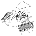
- FIG. 2 is an exploded view of FIG. 1 , but viewed from a different aspect
- FIG. 3 is an exploded view of an LED lamp of FIG. 2 ;
- FIG. 4 is an inverted view of FIG. 3 ;
- FIG. 5 is a schematic view of a switch of FIG. 2 , wherein the switch is at an opened position;
- FIG. 6 is a schematic view of a switch of FIG. 2 , wherein the switch is at a closed position.
- an outdoor LED lamp assembly (not labeled) comprises a receiving member 10 and a pair of LED lamps 20 assembled on opposite sides of the receiving member 10 .
- the receiving member 10 has a triangular configuration and consists of a top plate 14 , a bottom plate 12 opposite to the top plate 14 , a pair of mounting plates 16 connecting right and left edges of the top and bottom plates 14 , 12 , and a rear plate (not labeled) and a front plate (not labeled) connecting rear and front edges of the top and bottom plates 14 , 12 , respectively.
- a lamp holder 11 is secured to the rear plate of the outdoor LED lamp assembly.
- the lamp holder 11 is provided for securely connecting with a supporting post (not shown) whereby the outdoor LED lamp assembly can be supported by the supporting post.
- the bottom plate 12 and the top plate 14 are trapeziform and parallel to each other.
- the bottom plate 12 has a slightly larger area than that of the top plate 14 ; thus, the mounting plates 16 extend outwardly and downwardly from the edges of the top plate 14 to the edges of the bottom plate 12 .
- the rear plate is larger than the front plate; thus, the mounting plates 16 extend outwardly and rearwards from the front plate to the rear plate.
- Three spaced elongated screws 161 extend outwardly from each of the mounting plates 16 to be engaged with the LED lamps 20 .
- a pair of through holes 163 (only one shown) is defined in the mounting plates 16 .
- a driving circuit module 30 is received in the receiving member 10 to electronically connect with and supply power to the LED lamps 20 . Electric wires (not shown) extend from the driving circuit board 30 through the through holes 163 to enter the LED lamps 20 .
- a switch 40 is received in the receiving member 10 and electronically connects with the driving circuit board 30 .
- Each LED lamp 20 comprises a plurality of LED modules 21 , a heat sink 23 supporting and cooling the LED modules 21 , a plurality of reflectors 25 over the LED modules 21 , and a housing 27 mounted around a periphery of the heat sink 23 to enclose the LED modules 21 and the reflectors 25 therein.
- the heat sink 23 is made of a metal with a high degree of heat conductivity, such as copper or aluminum.
- the heat sink 23 comprises a rectangular base 231 and a plurality of fins 233 extending from the base 231 .
- the base 231 comprises a top plate (not labeled) and a bottom plate (not labeled) opposite to the top plate.
- the fins 233 extend from the top plate of the base 231 .
- a centre of the bottom plate of the base 231 protrudes three elongated planar surfaces 235 .
- the LED modules 21 are attached on the surfaces 235 .
- the surfaces 235 are angled with each other.
- Each LED module 21 comprises an elongated printed circuit board 213 and a plurality of spaced LEDs 211 evenly mounted on a side of the printed circuit board 213 .
- the LEDs 211 of each LED module 21 are arranged along a longitudinal direction of the printed circuit board 213 .
- Each LED module 21 is mounted in a thermally conductive relationship with the bottom plate of the heat sink 23 and electronically connects with the driving circuit module 30 .
- Each reflector 25 is located over the printed circuit board 213 of a corresponding LED module 21 .
- the reflector 25 comprises a rim 251 and a plurality of ribs (not labeled) within the rim 251 .
- the rim 251 and the ribs connect with each other to define a plurality of through holes 253 .
- the LEDs 211 are received in the through holes 253 , respectively.
- Light generated by the LEDs 211 is reflected by the reflectors 25 to increase the intensity of the light emitted from the LED lamps 20 .
- a plurality of sleeves 255 is formed in the reflector 25 along a thickness direction thereof.
- a plurality of screws (not shown) are used to extend through the sleeves 255 and the printed circuit boards 213 to threadedly engage with the heat sink 23 thereby to mount the reflectors 25 and the LED modules 21 on the heat sinks 23 .
- the housing 27 comprises a rectangular frame 271 engaging with the heat sink 23 , a transparent cover 272 enclosed in the frame 271 and covering a bottom opening (not labeled) of the frame 271 , and a rectangular fixture 273 located at a bottom of the frame 271 and mounting the cover 272 on the frame 271 .
- the frame 271 forms a plurality of protruding portions 2713 on inner surfaces thereof. Each protruding portion 2713 and each corner of the frame 271 define a screw hole 2715 therein. Screws (not shown) extend through the heat sink 23 and engage into a top portion of the screw holes 2715 to mount the frame 271 on the heat sink 23 .
- the LED modules 21 are enclosed in the frame 271 .
- a rectangular ring-shaped gasket 60 is sandwiched between the frame 271 and the heat sink 23 to enhance hermeticity of the connection between the frame 271 and the heat sink 23 .
- a plurality of connecting plates (not labeled) extends inwardly from bottom of the inner surfaces of the frame 271 .
- a plurality of supporting plates 2717 extends inwardly and downwardly from edges of the connecting plates to support the cover 272 .
- the fixture 273 presses the cover 272 against the supporting plates 2717 .
- Screws (not shown) extend through the fixture 273 and engage into a bottom portion of the screw holes 2715 to mount the fixture 273 on the frame 271 .
- a rectangular ring-shaped gasket 70 is sandwiched between the cover 273 and the supporting plates 2717 to enhance hermeticity of the connection between the cover 273 and the supporting plates 2717 .
- a centre of an elongated sidewall (not labeled) of the frame 271 defines three holes 2718 corresponding to the elongated screws 161 of the receiving member 10 .
- a nut 2716 is received in each of the holes 2718 to engage with a corresponding one of the elongated screws 161 .
- Two through holes 2719 are defined between the holes 2718 for extension of the electric wires from the driving circuit module 30 into the LED lamp 20 .
- a rectangular linking plate 50 is sandwiched between the elongated sidewall of the LED lamp 20 and the mounting plate 16 of the receiving member 10 .
- the linking plate 50 defines three mounting holes 51 corresponding to the holes 2718 of the frame 271 of the LED lamp 20 , and two holes 53 corresponding to the through holes 2719 of the frame 271 of the LED lamp 20 .
- the elongated screws 161 extend through the mounting holes 51 of the linking plates 50 , O-rings 55 , 57 to threadedly engage with the nuts 2716 in the holes 2718 of the frame 271 , thereby to mount the LED lamps 20 on the opposite sides of the receiving member 10 .
- the heat sinks 23 extend outwardly and upwardly from the mounting plates 16 of the receiving member 10 , as shown in FIG.
- the LED modules 21 are oriented toward a plurality of different directions, whereby the LED lamp assembly in accordance with the present invention can have a large illumination angle.
- the LED modules 21 have an intimate contact with the heat sinks 23 , the heat generated by the LEDs 211 can be timely dissipated to surrounding air by the fins 233 of the heat sinks 23 .
- the LED lamp assembly can work normally when the LEDs 211 are activated.
- the switch 40 is received in the receiving member 10 and mounted on the top plate 14 .
- the switch 40 has a rectangular configuration.
- the switch 40 comprises two groups of parallel control members (not labeled).
- Each group of control member comprises an operating member 41 extending downwardly from a bottom portion of the switch 40 , a first spring sheet 45 located at a top of the operating portion 41 , a second spring sheet 47 located at a top of the first spring sheet 45 , and a connecting member 43 secured to the first spring sheet 45 and sandwiched between the operating member 41 and the first spring sheet 45 .
- the first spring sheet 45 of one group of control member electronically connects with the driving circuit module 30 , and the corresponding second spring sheet 47 connects with one of positive and negative poles (not shown) of a power source (not shown).
- the first spring sheet 45 of another group of control member electronically connects with the driving circuit module 30 , and the corresponding second spring sheet 47 thereof connects with another one of the positive and negative poles (not shown) of the power source.
- Each operating member 41 comprises an elongated pressing plate 411 extending slantwise, outwardly and downwardly from the bottom of the switch 40 and a pellet 413 located at an outmost end of the pressing plate 411 .
- the connecting member 43 comprises a connecting pole 431 and a pressing block 433 perpendicular to the connecting pole 431 .
- a spring 42 surrounds the connecting pole 431 and is compressed between the pressing block 433 and a washer (not labeled) fixed to the connecting pole 431 at a position near the bottom of the switch 40 .
- the first spring sheet 45 comprises a supporting portion 451 to which the pressing block 433 of the connecting member 43 is securely attached and a connecting portion 453 electronically connecting with the driving circuit module 30 .
- a protruding point 4511 extends upwardly from a top surface of the supporting portion 451 of the first spring sheet 45 .
- a supporting point 471 extends downwardly from a bottom surface of the second spring sheet 47 to connect with the protruding point 4511 of the first spring sheet 45 when the operating member 41 is depressed by the bottom plate 12 of the receiving member 10 .
- the pressing plates 411 of the operating members 41 press the connecting poles 431 due to the bottom plate 12 of the receiving member 10 depressing the pellets 413 of the operating members 41 .
- the pressing blocks 433 of the connecting members 43 press the supporting portions 451 of the first spring sheets 45 .
- the protruding points 4511 of the supporting portions 451 connect with the supporting points 471 of the second spring sheets 47 .
- the switch 40 is closed (“ON”) so that current can flow from the power source through the switch 40 , the driving circuit module 30 to the LEDs 211 of the LED modules 21 . Accordingly, the LEDs 211 are driven to lighten
- the bottom plate 12 of the receiving member 10 is taken away and the operating members 41 are moved from the depressed position of FIG. 6 to the undepressed position of FIG. 5 .
- the first spring sheets 45 are spaced from and no longer electrical connected with the second spring sheets 47 .
- the switch 40 is opened (“OFF”). The current from the power source can no longer flow to the driving circuit module 30 and the LEDs 211 of the LED modules 21 , whereby the serviceman can securely proceed with the repair and maintenance of the outdoor LED lamp assembly in accordance with the present invention.
- the bottom plate 12 is mounted back on the receiving member 10 , whereby the operating members 41 are depressed and the switch 40 is closed (“ON”) again; thus, the current from the power source can flow to the LEDs 211 of the LED modules 21 to enable the LEDs 211 to lighten, and the serviceman can readily check the effectiveness of the repair or maintenance.
Landscapes
- Engineering & Computer Science (AREA)
- General Engineering & Computer Science (AREA)
- Physics & Mathematics (AREA)
- Geometry (AREA)
- Arrangement Of Elements, Cooling, Sealing, Or The Like Of Lighting Devices (AREA)
- Non-Portable Lighting Devices Or Systems Thereof (AREA)
- Fastening Of Light Sources Or Lamp Holders (AREA)
Applications Claiming Priority (3)
| Application Number | Priority Date | Filing Date | Title |
|---|---|---|---|
| CN2008100663432A CN101545594B (zh) | 2008-03-26 | 2008-03-26 | 发光二极管路灯 |
| CN200810066343.2 | 2008-03-26 | ||
| CN200810066343 | 2008-03-26 |
Publications (2)
| Publication Number | Publication Date |
|---|---|
| US20090244927A1 US20090244927A1 (en) | 2009-10-01 |
| US7810958B2 true US7810958B2 (en) | 2010-10-12 |
Family
ID=41116936
Family Applications (1)
| Application Number | Title | Priority Date | Filing Date |
|---|---|---|---|
| US12/133,401 Expired - Fee Related US7810958B2 (en) | 2008-03-26 | 2008-06-05 | Outdoor LED lamp assembly |
Country Status (2)
| Country | Link |
|---|---|
| US (1) | US7810958B2 (zh) |
| CN (1) | CN101545594B (zh) |
Cited By (6)
| Publication number | Priority date | Publication date | Assignee | Title |
|---|---|---|---|---|
| US20100002433A1 (en) * | 2008-07-04 | 2010-01-07 | Foxconn Technology Co., Ltd. | Led illumination device and light engine thereof |
| US20100296287A1 (en) * | 2009-05-19 | 2010-11-25 | Fu Zhun Precision Industry (Shen Zhen) Co., Ltd. | Led lamp |
| US20120218758A1 (en) * | 2011-02-28 | 2012-08-30 | Foxconn Technology Co., Ltd. | Illumination device |
| US20140185289A1 (en) * | 2011-02-18 | 2014-07-03 | Zumtobel Lighting Gmbh | Facade light comprising light-emitting diodes |
| DE212013000115U1 (de) | 2013-07-19 | 2015-01-12 | Limited Liability Company "Dis Plus" | LED-Beleuchtungsvorrichtung |
| WO2015106017A1 (en) * | 2014-01-10 | 2015-07-16 | Cooper Technologies Company | Assembly systems for modular light fixtures |
Families Citing this family (10)
| Publication number | Priority date | Publication date | Assignee | Title |
|---|---|---|---|---|
| US20110013392A1 (en) * | 2009-07-15 | 2011-01-20 | Little Jr William D | Lighting apparatus |
| US8360613B2 (en) * | 2009-07-15 | 2013-01-29 | Aphos Lighting Llc | Light feature |
| CN101998713A (zh) * | 2009-08-03 | 2011-03-30 | 东芝照明技术株式会社 | 电源装置、led照明灯及照明器具 |
| CN102052646B (zh) * | 2009-11-10 | 2012-02-29 | 海洋王照明科技股份有限公司 | 初始位置调节机构及其灯具 |
| JP5435799B2 (ja) * | 2010-03-29 | 2014-03-05 | パナソニック株式会社 | 道路用照明器具 |
| CN102155697B (zh) * | 2011-04-25 | 2013-01-30 | 东莞市百分百科技有限公司 | 路灯制备方法及实施该方法的led路灯 |
| CN102937259A (zh) * | 2012-11-22 | 2013-02-20 | 天津海宇光电科技有限公司 | 一种模块一体化led路灯 |
| US20150092410A1 (en) * | 2013-09-27 | 2015-04-02 | Lsi Industries, Inc. | Luminaire |
| KR20160005265A (ko) * | 2014-07-04 | 2016-01-14 | 주식회사 케이엠더블유 | 엘이디 조명장치 |
| US11486568B2 (en) * | 2020-10-25 | 2022-11-01 | Trolmaster Argo Instruments Co., Limited | Lamp radiator, lamp and lamp assembly |
Citations (7)
| Publication number | Priority date | Publication date | Assignee | Title |
|---|---|---|---|---|
| US6787999B2 (en) * | 2002-10-03 | 2004-09-07 | Gelcore, Llc | LED-based modular lamp |
| US20070103895A1 (en) * | 2005-11-09 | 2007-05-10 | Scott Riesebosch | Illumination System For Portable Insulated Containers |
| US7293898B2 (en) * | 2004-07-29 | 2007-11-13 | Princeton Tectonics, Inc. | Portable light |
| US20090097264A1 (en) * | 2007-10-12 | 2009-04-16 | Timothy Dunn | Lamp assembly utilizing light emitting diodes |
| US7588355B1 (en) * | 2008-03-19 | 2009-09-15 | Fu Zhun Precision Industry (Shen Zhen) Co., Ltd. | LED lamp assembly |
| US7637637B2 (en) * | 2008-04-16 | 2009-12-29 | Fu Zhun Precision Industry (Shen Zhen) Co., Ltd. | Outdoor LED lamp assembly |
| US7674013B2 (en) * | 2006-08-11 | 2010-03-09 | Honeywell International Inc. | Utility light |
-
2008
- 2008-03-26 CN CN2008100663432A patent/CN101545594B/zh not_active Expired - Fee Related
- 2008-06-05 US US12/133,401 patent/US7810958B2/en not_active Expired - Fee Related
Patent Citations (7)
| Publication number | Priority date | Publication date | Assignee | Title |
|---|---|---|---|---|
| US6787999B2 (en) * | 2002-10-03 | 2004-09-07 | Gelcore, Llc | LED-based modular lamp |
| US7293898B2 (en) * | 2004-07-29 | 2007-11-13 | Princeton Tectonics, Inc. | Portable light |
| US20070103895A1 (en) * | 2005-11-09 | 2007-05-10 | Scott Riesebosch | Illumination System For Portable Insulated Containers |
| US7674013B2 (en) * | 2006-08-11 | 2010-03-09 | Honeywell International Inc. | Utility light |
| US20090097264A1 (en) * | 2007-10-12 | 2009-04-16 | Timothy Dunn | Lamp assembly utilizing light emitting diodes |
| US7588355B1 (en) * | 2008-03-19 | 2009-09-15 | Fu Zhun Precision Industry (Shen Zhen) Co., Ltd. | LED lamp assembly |
| US7637637B2 (en) * | 2008-04-16 | 2009-12-29 | Fu Zhun Precision Industry (Shen Zhen) Co., Ltd. | Outdoor LED lamp assembly |
Cited By (10)
| Publication number | Priority date | Publication date | Assignee | Title |
|---|---|---|---|---|
| US20100002433A1 (en) * | 2008-07-04 | 2010-01-07 | Foxconn Technology Co., Ltd. | Led illumination device and light engine thereof |
| US7926982B2 (en) * | 2008-07-04 | 2011-04-19 | Foxconn Technology Co., Ltd. | LED illumination device and light engine thereof |
| US20100296287A1 (en) * | 2009-05-19 | 2010-11-25 | Fu Zhun Precision Industry (Shen Zhen) Co., Ltd. | Led lamp |
| US8021024B2 (en) * | 2009-05-19 | 2011-09-20 | Fu Zhun Precision Industry (Shen Zhen) Co., Ltd. | LED lamp |
| US20140185289A1 (en) * | 2011-02-18 | 2014-07-03 | Zumtobel Lighting Gmbh | Facade light comprising light-emitting diodes |
| US9464766B2 (en) * | 2011-02-18 | 2016-10-11 | Zumtobel Lighting Gmbh | Facade light comprising light-emitting diodes |
| US20120218758A1 (en) * | 2011-02-28 | 2012-08-30 | Foxconn Technology Co., Ltd. | Illumination device |
| DE212013000115U1 (de) | 2013-07-19 | 2015-01-12 | Limited Liability Company "Dis Plus" | LED-Beleuchtungsvorrichtung |
| WO2015106017A1 (en) * | 2014-01-10 | 2015-07-16 | Cooper Technologies Company | Assembly systems for modular light fixtures |
| US9353924B2 (en) | 2014-01-10 | 2016-05-31 | Cooper Technologies Company | Assembly systems for modular light fixtures |
Also Published As
| Publication number | Publication date |
|---|---|
| CN101545594A (zh) | 2009-09-30 |
| US20090244927A1 (en) | 2009-10-01 |
| CN101545594B (zh) | 2010-09-29 |
Similar Documents
| Publication | Publication Date | Title |
|---|---|---|
| US7810958B2 (en) | Outdoor LED lamp assembly | |
| US7588355B1 (en) | LED lamp assembly | |
| US7637637B2 (en) | Outdoor LED lamp assembly | |
| US7758211B2 (en) | LED lamp | |
| US7837362B2 (en) | LED lamp with an improved sealed structure | |
| US8083374B2 (en) | LED lamp | |
| US7744258B2 (en) | Outdoor LED lamp assembly | |
| US7670034B2 (en) | LED lamp | |
| US7699498B2 (en) | LED lamp | |
| US8021024B2 (en) | LED lamp | |
| US7862210B2 (en) | LED lamp with heat sink assembly | |
| US20100165627A1 (en) | Light emitting module and led lamp employing it | |
| US7963672B2 (en) | LED lamp | |
| US20080080188A1 (en) | Modulized Assembly Of A Large-sized LED Lamp | |
| US8858024B2 (en) | Illuminating apparatus and illuminating module | |
| US8061875B2 (en) | LED lamp | |
| CN101660737A (zh) | 发光二极管灯具 | |
| US7465066B2 (en) | Water-resistant illumination apparatus | |
| US20100097798A1 (en) | LED light module for portable lighting | |
| US20090046469A1 (en) | Light Emitting Diode Module | |
| JP3150841U (ja) | Led照明装置の組み合わせ構造 | |
| US20120092879A1 (en) | Lamp incorporating clips | |
| JP2006172893A (ja) | 照明器具 | |
| US8016453B2 (en) | LED lamp assembly | |
| US20090268451A1 (en) | Led lamp assembly |
Legal Events
| Date | Code | Title | Description |
|---|---|---|---|
| AS | Assignment |
Owner name: FOXCONN TECHNOLOGY CO., LTD., TAIWAN Free format text: ASSIGNMENT OF ASSIGNORS INTEREST;ASSIGNORS:LIU, YOU-XUE;HE, LI;REEL/FRAME:021048/0339 Effective date: 20080526 Owner name: FU ZHUN PRECISION INDUSTRY (SHEN ZHEN) CO., LTD., Free format text: ASSIGNMENT OF ASSIGNORS INTEREST;ASSIGNORS:LIU, YOU-XUE;HE, LI;REEL/FRAME:021048/0339 Effective date: 20080526 |
|
| REMI | Maintenance fee reminder mailed | ||
| LAPS | Lapse for failure to pay maintenance fees | ||
| STCH | Information on status: patent discontinuation |
Free format text: PATENT EXPIRED DUE TO NONPAYMENT OF MAINTENANCE FEES UNDER 37 CFR 1.362 |
|
| FP | Expired due to failure to pay maintenance fee |
Effective date: 20141012 |