US7809449B2 - Coupling of safe fieldbus systems - Google Patents
Coupling of safe fieldbus systems Download PDFInfo
- Publication number
- US7809449B2 US7809449B2 US11/368,325 US36832506A US7809449B2 US 7809449 B2 US7809449 B2 US 7809449B2 US 36832506 A US36832506 A US 36832506A US 7809449 B2 US7809449 B2 US 7809449B2
- Authority
- US
- United States
- Prior art keywords
- safety
- data
- data structure
- safe
- independent
- Prior art date
- Legal status (The legal status is an assumption and is not a legal conclusion. Google has not performed a legal analysis and makes no representation as to the accuracy of the status listed.)
- Active, expires
Links
Images


Classifications
-
- H—ELECTRICITY
- H04—ELECTRIC COMMUNICATION TECHNIQUE
- H04L—TRANSMISSION OF DIGITAL INFORMATION, e.g. TELEGRAPHIC COMMUNICATION
- H04L12/00—Data switching networks
- H04L12/28—Data switching networks characterised by path configuration, e.g. LAN [Local Area Networks] or WAN [Wide Area Networks]
- H04L12/46—Interconnection of networks
- H04L12/4604—LAN interconnection over a backbone network, e.g. Internet, Frame Relay
- H04L12/462—LAN interconnection over a bridge based backbone
-
- H—ELECTRICITY
- H04—ELECTRIC COMMUNICATION TECHNIQUE
- H04L—TRANSMISSION OF DIGITAL INFORMATION, e.g. TELEGRAPHIC COMMUNICATION
- H04L12/00—Data switching networks
- H04L12/66—Arrangements for connecting between networks having differing types of switching systems, e.g. gateways
-
- H—ELECTRICITY
- H04—ELECTRIC COMMUNICATION TECHNIQUE
- H04L—TRANSMISSION OF DIGITAL INFORMATION, e.g. TELEGRAPHIC COMMUNICATION
- H04L41/00—Arrangements for maintenance, administration or management of data switching networks, e.g. of packet switching networks
- H04L41/08—Configuration management of networks or network elements
- H04L41/0803—Configuration setting
- H04L41/0806—Configuration setting for initial configuration or provisioning, e.g. plug-and-play
-
- G—PHYSICS
- G05—CONTROLLING; REGULATING
- G05B—CONTROL OR REGULATING SYSTEMS IN GENERAL; FUNCTIONAL ELEMENTS OF SUCH SYSTEMS; MONITORING OR TESTING ARRANGEMENTS FOR SUCH SYSTEMS OR ELEMENTS
- G05B2219/00—Program-control systems
- G05B2219/20—Pc systems
- G05B2219/25—Pc structure of the system
- G05B2219/25205—Encrypt communication
-
- H—ELECTRICITY
- H04—ELECTRIC COMMUNICATION TECHNIQUE
- H04L—TRANSMISSION OF DIGITAL INFORMATION, e.g. TELEGRAPHIC COMMUNICATION
- H04L12/00—Data switching networks
- H04L12/28—Data switching networks characterised by path configuration, e.g. LAN [Local Area Networks] or WAN [Wide Area Networks]
- H04L12/40—Bus networks
- H04L2012/40208—Bus networks characterized by the use of a particular bus standard
Definitions
- the invention relates to a method and to an apparatus, which is designed to carry out the method, for coupling at least (field)bus/network systems having different safety mechanisms in order to process safety-relevant or safety-critical data.
- safety-relevant data and safety-critical data which are referred to in general in the following description and in the claims as safety data, means data which is respectively relevant and critical to the control of safety-relevant or safety-critical processes or process elements which, when a fault occurs, result in a hazard to people and/or to material goods as well which cannot be ignored, so that a subsequent process which is coupled to this process, and/or a system which includes this process must be changed to a safe state.
- Examples of processes such as these are chemical processes in which it is essential to maintain critical parameters within a specified range, complex machine control systems, for example in the case of a hydraulic press or a production line, in which, for example, the starting up of a press/cutting tool can represent a safety-relevant process element.
- Further examples of safety-relevant processes and process elements are the monitoring of guard gratings, guard doors or light barriers, the control of two-handed switches, or else the reaction to emergency-off switches.
- EP 1 188 096 B1 discloses a control system for a safety-relevant process with a field bus, via which a control unit for controlling the safety-relevant process and a signaling unit which is linked to the safety-relevant process via I/O channels are connected.
- these units have safety-related devices by means of which units which are intrinsically not safe are intended to become safe units.
- a multiple-channel processing structure which is provided by a computer is provided, in which case an error in a processing channel can be identified, and possibly corrected, on the basis of a result which is not the same as that of another redundant processing channel.
- the general expression computer essentially means any type of data processing devices such as microcomputers, microprocessors, microcontrollers or else PCs.
- WO 01/15385 A2 also relates to the control of safety-relevant processes using a (field)bus system based on a safety mechanism, in which the units involved in the control of the safety-relevant process once again generally have redundant processing channels.
- Each of the redundant channels has a computer, and these computers monitor one another.
- This multiple-channel structure is changed to a single-channel structure by means of a further computer, which is connected to the fieldbus.
- WO 01/15391 A1 and Laid-Open Specification DE 199 39 567 A1 disclose further examples of safe bus subscribers.
- a safety mechanism is provided with redundant processing channels and/or computers which monitor one another with respect to safe protocol creation, with a subsequent change from the two-channel system to the single-channel system via a further computer which is coupled to the bus, is connected to a protocol chip or has this integrated in it.
- Patent Specification DE 195 32 639 C2 which relates to a further device for single-channel transmission of data which is formed by means of two redundant computers, integrates the function of bus coupling into one of the two redundant computers, in order to reduce the circuit complexity.
- DE 100 65 907 A1 discloses a safety mechanism which is based on the principle of “redundancy with cross-comparison”, for protected data transport for data transmission on parallel or serial networks or buses, in which case an intermediate register with two logically identical data areas is used for the change from the two-channel to the single-channel system.
- German application with the file reference DE 10 2004 039932.8 which was submitted by the same applicant as the present invention on Aug. 17 2004, relates to a further approach to safe bus coupling of safety-relevant processes, in which freedom from action and independence are ensured for the creation of a safety-based protocol.
- the application with the file reference DE 10 2004 039932.8 whose entire disclosure is referred to here, in this case provides a method for single-channel bus coupling for a safety-critical process, in which a data record which is relevant for the safety-critical process is processed via at least two redundant processing channels in accordance with identical rules for in each case one safety-based protocol, and the redundant safety-based protocols for single-channel bus coupling are combined again to form a common safety-based protocol, to be precise by each of the processing channels accessing a common intermediate register, with write authorization being allocated only once for each register location, in such a way that the common safety-based protocol, that is to say the safety message to be transmitted, is composed in elements by in each case writing different elements of the respective safety-based protocols.
- One object of the present invention is to provide a way to couple widely differing fieldbus or network systems each having their own safety mechanisms in such a way as to ensure the transmission of safety data between at least two bus/network systems with different safety mechanisms.
- the invention for coupling at least two (field)bus/network systems each having different safety mechanisms, in particular each having proprietary safety mechanisms, the invention provides for safety data which is to be transmitted between the different system-based safety mechanisms to be processed additionally using a safe data structure which is defined but is system-independent.
- one major advantage of the invention is that a safe communication relationship, which is independent of any (field)bus/network system and is thus essentially local, can be set up in a simple manner between widely different (field)bus/network systems, avoiding direct conversion between two different safety mechanisms of different (field)bus/network systems with the safe conversion mechanisms which are in each case required for this purpose and must be adapted differently. It is thus for the first time possible in this way to also couple (field)bus/network systems which each have proprietary safety mechanisms.
- each of the data processing modules is coupled to one of the system-based safety mechanisms, in which case at least the at least one data processing module is designed to convert safety data which is to be transmitted and is in the form of one or more channels to the safe data structure which is defined but is system-independent, and at least one other data processing module is designed for safety-based evaluation of the system-independent safe data structure in order to produce safety data in the form of one or more channels.
- Each data processing module is preferably designed for conversion to both coupling directions, safety data which is to be transmitted between the systems can be converted in an extremely flexible and versatile manner from a system-dependent safe data structure, which is in the form of one or more channels, before being transmitted using the defined, but system-independent, safe data structure and/or safety data to be transmitted can be converted to a multiple-channel or single-channel system-dependent safe data structure after being transmitted using the safe data structure which is defined but system-independent.
- the invention provides that a data structure which is in each case to be converted from one safe data structure to another safe data structure is advantageously first of all evaluated on a safety basis, and a data record, which has been evaluated, is in the form of one or more channels after evaluation and comprises “raw data” is converted to the respective other safe data structure.
- the safe data processing modules are thus essentially decoupled from any system-dependent safety requirements.
- the safety data which is processed additionally using a safe data structure which is defined but is system-independent is transmitted within a unit, which is involved with a process to be controlled, of one of the systems to be coupled, to be precise between a safety-related device, which processes safety data that is relevant for this process, of the unit and at least one (field)bus/network connection of the unit.
- the data processing modules are expediently integrated in the unit which is involved with the process to be controlled in such a way that at least one of the at least two data processing modules is integrated in the safety-related device, and at least one other of the data processing modules is integrated with the (field)bus/network connection.
- One particularly preferred embodiment provides that a set of input/output data, which is in the form of one or more channels, of the process to be controlled is converted to the safe data structure which is defined but is system-independent, or is obtained from the safe data structure which is defined but is system-independent by evaluation of that safe data structure which is defined but is system-independent.
- At least one data processing module which is integrated in the safety-related device is expediently designed for conversion of safety data, which comprises a set of input/output data in the form of one or more channels, for the process to be controlled to the safe data structure which is defined but system-independent, and/or to evaluate the safe data structure which is defined but system-independent for single-channel or multiple-channel production of a set of safety data comprising input/output data.
- the unit may be a subscriber unit which comprises at least one single-channel or multiple-channel input and/or output for connection of a process to be controlled, such that safe inputs/outputs to a safety-relevant process can also be included using the invention. If safe inputs/outputs can be included via the safety-related device, this safety input data may be in the form of “raw data” at this stage.
- the unit may also be a control unit which, for example, generates safety data to be processed.
- each existing bus subscriber unit or bus control unit can thus be adapted just by minor modifications for the extremely flexible coupling according to the invention of different systems, and can thus be provided with integrated gateway functionality, as well.
- Units such as these which are designed to carry out the method according to the invention also, on an application-specific basis, have modular units, for example INLINE units, and the bus/network connection can in consequence also be integrated in an INLINE station that is formed by the unit.
- the conversion to the data structures which are safe on a system-independent basis is preferably carried out in a protected form for a single-channel transmission, preferably in accordance with the safety functionality disclosed in DE 10 2004 039932.8, in which case essentially any desired hardware structures which are not safe, for example microprocessors such as USC4, serial buses such as I 2 C or SPI, and/or a plurality of coupling memories of intermediate registers, for example in the form of DPMs (dual port memories) can also be used within the unit for the transmission of data structures protected on a system-independent basis in this way between respective data processing modules, in an expedient and cost-saving manner.
- microprocessors such as USC4
- serial buses such as I 2 C or SPI
- DPMs dual port memories
- the data processing modules in consequence preferably comprise at least two redundant, interacting module units, with the module units being coupled on the output side to a non-safe coupling component by means of this non-safe coupling component for transferring a data structure which is jointly protected on a system-independent basis, and/or be coupled on the input side with a non-safe coupling component for safety-based reading of a data structure, which is protected on a system-independent basis, from this coupling component.
- the internal communication connection is protected via a non-safe component which, in a further preferred embodiment, is based in a single channel form on safe control of a unit which is involved in a safety-critical process, and the units mounted downstream from this by means of safety mechanisms, which are listed in IEC 61508, for variable memory areas and communication interfaces in accordance with SIL 3, that is to say in particular by means of CRC, compliance with time expectations and time-out mechanisms.
- a non-safe component which, in a further preferred embodiment, is based in a single channel form on safe control of a unit which is involved in a safety-critical process, and the units mounted downstream from this by means of safety mechanisms, which are listed in IEC 61508, for variable memory areas and communication interfaces in accordance with SIL 3, that is to say in particular by means of CRC, compliance with time expectations and time-out mechanisms.
- the invention thus in a simple manner allows safety-based integration of specific safety-related devices, for example of a safe Interbus controller even in units with different (field)bus/network interfaces.
- the provision of a unit designed according to the invention with integrated safe gateway functionality to different network systems is also within the scope of the invention.
- the data processing modules may be formed on an application-specific basis by hardware and/or software such that they can be integrated in units based on widely differing systems with just minor modifications to already in-use communication firmware and essentially without any modification to hardware structures.
- the invention thus in general allows the coupling of unit with a specific safety-related device to other safety-related communication systems, in which case it is also possible to effectively use proven techniques and methods, with appropriate modification, thus ensuring a high level of reuse and a high level of modularity.
- a unit with a safety-related device based on the INTERBUS for example a safe controller which is integrated as a plug-on board or in the layout for a unit which is involved in a safety-critical process can be coupled to other safety-related communication systems, such as CAN SAFETY, PROFISAFE, or the like.
- the invention thus also covers a computer-legible medium with information stored in it which, read by a computer, in particular by a computer for a bus or network unit which is involved in a process to be controlled, will interact with the computers in order to carry out the method according to the invention.
- FIGS. 1 a and 1 b show two highly simplified function diagrams, in each case of a direct adaptation of a two-channel hardware structure of a safety-related device of a unit which is involved in a process to be controlled to a fieldbus connection for a fieldbus with a different safety-based mechanism according to the invention
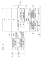
- FIG. 2 shows a highly simplified function diagram of an example of an implementation of a gateway between two different safe fieldbus systems according to the invention
- FIGS. 3 a and 3 b show two highly simplified function diagrams of one example of a data flow according to the invention between an IB safety and a system-independent safe data structure and between the system-independent safe structure and the IB safety data structure, based on the function diagram shown in FIG. 2 .
- FIGS. 1 a and 1 b show two highly simplified function diagrams of bus subscriber units designed according to the invention, which each provide direct adaptation of a two-channel hardware structure of an integrated safety-related device to a different safety-related fieldbus connection according to the invention.
- FIG. 1 a one embodiment is in this case sketched in FIG. 1 a , in which two fieldbus nodes or protocol chips operate in a redundant manner on a fieldbus 401 which itself has a proprietary safety mechanism, for example in the case of different CAN solutions.
- microprocessors iC 1 and iC 2 which are coupled to the bus 401 integrate the respective protocol chip, via which safety-based (SB) data items 321 and 322 , which are formed with the proprietary safety mechanism, are injected into the bus 401 , or are output from the bus 401 .
- SB safety-based
- just one fieldbus node or protocol chip 313 to which two microprocessors iC 1 and iC 2 , 311 and 312 , respectively, are connected acts on the bus 402 of a system with a proprietary safety mechanism, that is to say for injection and outputting SB data items 331 and 332 which are formed by a proprietary safety mechanism, so that, in this case, a transition is thus provided between a two-channel-system and a single-channel system, for example in the case of Profisafe.
- a proprietary safety mechanism for bus coupling is thus provided with two redundant computers or processing channels in order to create a safe protocol for bus injection and for evaluation of the safe protocol for bus outputting.
- the procedure which will be described in the following text with reference to FIG. 1 a relates to bus injection of safety data items which are obtained via two safe channels SK 1 and SK 2 , which process input/output data identified by the reference symbols 101 and 102 , for the safety-related device.
- the safe channels 101 and 102 in one practical embodiment in this case each comprise a CPU with the necessary peripheral components.
- An associated watchdog 105 monitors and ensures suitability for function.
- each of the safe channels 101 and 102 which process the safety data is connected to input and/or output units, such as sensors and/or actuators, which are not illustrated but are associated with the safety-critical process to be coupled thereto.
- Identical input data items which are relevant for the safety-critical process are preferably made available to the safe channels 101 and 102 for a bus subscriber unit with a sensor-end application, with these input data items expediently initially being stored.
- input data to be protected is located, for example, in appropriate memories.
- the redundant input data items are then processed by means of integrated LSL module units, which are identified by 10 for the safe channels 101 and 102 to form common data items with a locally protected data structure, that is to say a data structure which is protected independently of the (field)bus/network system.
- a locally protected data structure that is to say a data structure which is protected independently of the (field)bus/network system.
- This data or protocol structure which is protected independently of the (field)bus/network system is referred to in the following text as the LSL (Local Safety Layer).
- the input data items which are in the form of raw data items, are first of all processed in a redundant form using the same rules for in each case one safety-based protocol, which are identical provided that no errors, faults or failures occur during the calculation, and satisfy the requirements of the standard for safety-based transmission.
- a common LSL is then worked out from the redundant safety-based protocols, so that LSL data items, which are identified by 215 , can then be transferred on a single channel basis, for example based on a point-to-point connection, to the fieldbus/network connection with a variable data length for the proprietary system to be coupled thereto.
- the LSL data items 215 which are protected by means of the LSL can thus be transferred via non-safe hardware structures and are formed, using the safety mechanism disclosed in the German application DE 10 2004 039932.8, by means of element-by-element combination of data items of the redundant safety-based protocols in a buffer store or intermediate register, which is identified by the reference symbol 200 , such as the DPM that is shown.
- the safety analysis of the redundant architecture with respect to the LSL module units 10 can thus be ended initially by the storage of the LSL data items 215 in the non-safe memory 200 . This is where the safety mechanism LSL comes into action, because the errors or faults which are possible from this point on are considered and must be coped with as before for the rest of the transmission.
- One error which can occur in this context from the principle for the checking and certification of “Bus systems for the transmission of safety-relevant messages” is message corruption.
- the LSL data 210 is, however, first of all once again evaluated on a safety-basis by LSL module units 10 in accordance with the LSL definition. This evaluation is preferably carried out, as shown in FIGS. 1 a and 1 b , with two-channel redundancy, with or without diversity.
- the evaluated data items are then introduced, once again as raw data items, into the actual safety-based proprietary bus network protocol.
- the proprietary safety mechanisms of the respective coupled safe system then apply, on the basis of which the corresponding safe SB data items 321 and 322 as shown in FIG. 1 a , or 331 and 332 as shown in FIG. 1 b , are produced from the raw data items and are injected into the respective bus 401 or 402 .
- a defined or definable access rule is thus preferably provided for the element-by-element combination of the safety-based protocol, which is in a redundant application-specific form, or possibly on an application-specific basis for the element-by-element combination of the redundant raw data items in order to form an LSL, which is to be transmitted on a single channel, using the safety mechanism as disclosed in the German application DE 10 2004 039932.8, which access rule admittedly gives the LSL module units 10 full read rights to the buffer store 200 , but controls writing rights to the buffer store 200 .
- the access rule stipulates that, from each of the redundant LSL module units 10 , only the parts of the respectively calculated safety-based protocol for the formation of the LSL can be written to the corresponding memory locations in the buffer store 200 for which the respective LSL module units 10 in each case have writing authorization.
- only one writing authorization is preferably defined in each case for one communication direction for each memory or register location.
- both LSL module units 10 are in each case able to calculate all of the LSL data items, so that this has a positive effect on the required length of the data structure, since all of the data bits with the various safety mechanisms are already known in the redundant LSL module units 10 , and no additional data bits need to be transmitted to allow the correct calculation to be deduced at the receiver end. Furthermore, this ensures that one of the LSL module units 10 on its own is not able to send an LSL, with the control of the authorization to write data, which can in each case be allocated only once, in a register cell representing an option which can be implemented easily and is highly efficient in order to ensure cost-effective, considerably increased safety independently of the LSL and of a system that is being used.
- Complete read access to the buffer store 200 allows all of the data items to be compared in a simple form in that, on the one hand, it is easily possible to check whether the jointly formed LSL which, for example, satisfies the safety requirements for single transmission in accordance with SIL 3 IEC 61508 is error-free, to be precise by respective verification against its own safety-based protocol which is formed separately in advance. Furthermore, the completely comprehensive read access for each of the LSL module units 10 makes it possible to carry out a check, which can expediently be carried out as a primary item in the control/monitoring/regulation of a safety-critical process, to determine whether the access rule is in general carried out without errors. For this purpose, in particular, a check is carried out to determine whether the calculated data items are written to one of the respective module units 10 of the redundant processing channels exclusively, although this is guaranteed only to the respectively assigned memory addresses in the buffer store 200 .
- the use of the invention thus ensures a flexible, bus-independent modular safety-based communication and hardware structure in a bus subscriber/bus control unit. Furthermore, a high level of reuse as a platform is ensured, particularly in the case of a safety-related device which has a programming interface and is integrated or can be integrated in a bus subscriber/bus control unit such as this. In consequence, the invention allows rapid coupling to existing or future fieldbus/network systems, with the high performance of the safety-related device of the bus unit being maintained, since the communication is moved with the (field)bus/network system to be coupled thereto.
- gateway functions to be provided in a simple manner between widely different proprietary safety-based (field)bus/network systems, as will be described in more detail in the following text using the example of an additional CAN safety application together with INTERBUS safety communication.
- the safety-related device of a correspondingly adapted bus subscriber unit integrates redundant LSL module units 10 in addition to redundant IB safety module units 30 , which build on an INTERBUS safety protocol with the redundant safety channels 101 and 102 .
- a non-safe first DPM is coupled to the safety-related module units 10 and 30 as a coupling memory 201 for recording/transferring the LSL data items 215 , which are protected via the LSL, and the IB safety data items 366 , which are protected by the INTERBUS safety protocol.
- the coupling memory 201 is connected to an INTERBUS-specific control unit or CPU 360 with an integrated or external protocol chip 361 , thus providing a first INTERBUS-based fieldbus node for an INTERBUS safety bus 403 .
- Safety data items which are to be output or injected from or to the bus 403 via the protocol chip 361 are based on the INTERBUS safety protocol, and are correspondingly in the form of IB safety data 366 .
- non-protected standard data items 365 can be injected and output via the protocol chip 361 .
- a further DPM is connected to this INTERBUS-specific control unit or CPU 360 as an additional coupling memory 202 to which a safety-based CAN bus connection is fitted.
- the coupling can also be made via other media, for example by means of SPI, Wireless, Multi Port Memory, PCI express.
- the safety-based CAN bus connection is designed essentially as described with reference to FIG. 1 a , in which case standard data items 305 which are not protected can also be injected and output via the iC 1 with the integrated protocol chip 361 .
- the safety mechanisms described above can be used once again in a corresponding manner for the change from the coupling memory 202 to the two-channel structure of the CAN bus connection.
- a further coupling memory 371 can optionally be connected to the INTERBUS-specific control-unit or CPU 360 with, for example, a further optional (safe) control system 372 being provided on it.
- a data flow which is based on the function diagram shown in FIG. 2 , between an IB safety data structure and the specific data structure of a further system with a proprietary safety mechanism or between the specific data structure of the further system with a proprietary safety mechanism and the IB safety data structure will be described by way of example in the following text with reference to FIGS. 3 a and 3 b , with the area which comprises non-safe hardware structures being annotated “NS”, and the safe area being annotated “S”.
- protected IB safety data 366 which is output via the INTERBUS-based fieldbus connection 360 , 361 is supplied, for gateway functionality purposes, first of all to the coupling memory 201 in order to be passed on further, for example by means of a microprocessor that is not illustrated.
- the IB safety data 366 is read by the redundant IB safety module units 30 of the safety-based device, and is evaluated to form “raw data” items 20 .
- These redundant “raw data items” are then processed by the redundant LSL module units 10 of the safety-related device to form locally protected LSL data items 215 , and are once again supplied in a combined form to the coupling memory 201 in order to be passed on further on one channel.
- the locally protected LSL data items 215 are supplied, for example by means of a microprocessor that is not illustrated, to the coupling memory 202 in order to be passed on further.
- the LSL data items 215 are read and evaluated by the redundant LSL module units 10 of the fieldbus connection for the system with a proprietary safety mechanism, for example for a CAN bus.
- LSL data items 215 are read and then evaluated by the redundant LSL module units 10 of the fieldbus connection for the system with a proprietary safety mechanism, after being passed on to at least one further coupling device or directly from the coupling memory 201 .
- the redundant “raw data items” which are evaluated during the change from the single-channel structure to the multiple-channel structure are then embedded in the safety-based proprietary protocol by means of the redundant microprocessors, which are coupled to the proprietary (field)bus/network system and each have an integrated protocol chip 301 and 302 , and are injected into the system as SB data items 321 and 322 that are formed with the proprietary safety mechanism.
- FIG. 3 b shows the communication in the opposite sense.
- protected SB data items are output via the fieldbus connection that is based on the proprietary safety mechanism are evaluated, and locally protected LSL data items are supplied in a corresponding manner via the safety-based LSL module units to the coupling memory 202 , in order to be passed on further.
- the LSL data items are read from this memory by the redundant LSL module units 10 of the safety-related device, and are evaluated to form “raw data items” 20 .
- redundant “raw data items” are then processed by the redundant IB safety module units 30 of the safety-related device to form IB safety data items, and are once again supplied in a combined form to the coupling memory 201 in order to be passed on further on one channel. From there, the IB safety data items are transferred to the INTERBUS-based fieldbus connection, for bus injection.
- the coupling memory 201 is thus used for one-channel transfer of data items which are protected on a system-specific basis, and are locally protected.
- local inputs/outputs can also be connected via the safe channels 101 and 102 , so that it is also possible to include local safety input and/or output data in the communication path according to the invention within the unit, which is possibly also a modular unit.
Landscapes
- Engineering & Computer Science (AREA)
- Computer Networks & Wireless Communication (AREA)
- Signal Processing (AREA)
- Hardware Redundancy (AREA)
- Communication Control (AREA)
- Small-Scale Networks (AREA)
Applications Claiming Priority (3)
| Application Number | Priority Date | Filing Date | Title |
|---|---|---|---|
| DE102005010820.2A DE102005010820C5 (de) | 2005-03-07 | 2005-03-07 | Kopplung von sicheren Feldbussystemen |
| DE102005010820 | 2005-03-07 | ||
| DE102005010820.2 | 2005-03-07 |
Publications (2)
| Publication Number | Publication Date |
|---|---|
| US20060229737A1 US20060229737A1 (en) | 2006-10-12 |
| US7809449B2 true US7809449B2 (en) | 2010-10-05 |
Family
ID=36078679
Family Applications (1)
| Application Number | Title | Priority Date | Filing Date |
|---|---|---|---|
| US11/368,325 Active 2027-04-26 US7809449B2 (en) | 2005-03-07 | 2006-03-03 | Coupling of safe fieldbus systems |
Country Status (4)
| Country | Link |
|---|---|
| US (1) | US7809449B2 (es) |
| EP (1) | EP1701270B1 (es) |
| DE (1) | DE102005010820C5 (es) |
| ES (1) | ES2528182T3 (es) |
Cited By (8)
| Publication number | Priority date | Publication date | Assignee | Title |
|---|---|---|---|---|
| US20050113942A1 (en) * | 2003-11-21 | 2005-05-26 | Rosemount Inc. | Process device with supervisory overlayer |
| US20080258253A1 (en) * | 2003-10-08 | 2008-10-23 | Wolfgang Fey | Integrated Microprocessor System for Safety-Critical Regulations |
| US20100250813A1 (en) * | 2009-03-25 | 2010-09-30 | Siemens Ag | Safety-oriented Automation System Having Automatic Address Recovery |
| US20110264240A1 (en) * | 2010-04-21 | 2011-10-27 | General Electric Company | Systems and methods for facilitating communication with a fieldbus device |
| US20150169493A1 (en) * | 2012-12-24 | 2015-06-18 | Festo Ag & Co. Kg | Field Unit and a Method for Operating an Automation System |
| US20190294124A1 (en) * | 2018-03-20 | 2019-09-26 | Fisher-Rosemount Systems, Inc. | Long-Haul Safety System Trips |
| US10705498B2 (en) * | 2016-02-10 | 2020-07-07 | Phoenix Contact Gmbh & Co. Kg | Method and device for monitoring data processing and transmission in a security chain of a security system |
| US11778073B2 (en) | 2020-05-19 | 2023-10-03 | Beckhoff Automation Gmbh | Protocol converter and automation system |
Families Citing this family (14)
| Publication number | Priority date | Publication date | Assignee | Title |
|---|---|---|---|---|
| DE102006002824B4 (de) * | 2006-01-19 | 2008-10-09 | Phoenix Contact Gmbh & Co. Kg | Verfahren und Vorrichtung zur Umwandlung mehrkanalig vorliegender Nachrichten in eine einkanalige sichere Nachricht |
| US20080123677A1 (en) * | 2006-08-31 | 2008-05-29 | Honeywell International Inc. | System management bus port switch |
| US20080059682A1 (en) * | 2006-08-31 | 2008-03-06 | Honeywell International Inc. | Method to embed protocol for system management bus implementation |
| US20080084886A1 (en) * | 2006-10-09 | 2008-04-10 | Honeywell International Inc. | System management bus port router |
| DE102007025892A1 (de) * | 2007-06-01 | 2008-12-11 | Phoenix Contact Gmbh & Co. Kg | Werkzeugerkennung im Profinet |
| DE102007063291A1 (de) * | 2007-12-27 | 2009-07-02 | Robert Bosch Gmbh | Sicherheitssteuerung |
| DE202008003988U1 (de) * | 2008-03-22 | 2009-08-06 | Leuze Lumiflex Gmbh + Co. Kg | Busknoten eines Profinet-Bussystems |
| EP2783495B1 (en) * | 2011-11-22 | 2016-04-13 | HMS Industrial Networks AB | Safety system |
| DE102012208134B4 (de) * | 2012-05-15 | 2013-12-05 | Ifm Electronic Gmbh | Verfahren zur fehlersicheren Ansteuerung von Aktuatoren über ein Bussystem |
| EP2741451B1 (de) * | 2012-12-06 | 2017-04-26 | Sick Ag | Verfahren zum Anbinden eines Hardwaremoduls an einen Feldbus |
| DE102016107491A1 (de) * | 2016-04-22 | 2017-10-26 | Beckhoff Automation Gmbh | Verbindungseinheit, Überwachungssystem und Verfahren zum Betreiben eines Automatisierungssystems |
| EP3620869A1 (de) * | 2018-09-10 | 2020-03-11 | Siemens Aktiengesellschaft | Verfahren und umsetzungskomponente für den datenaustausch zwischen zwei systemen mit verschiedenen sicherheitskonzepten für funktionale sicherheit |
| US10838386B1 (en) * | 2019-09-26 | 2020-11-17 | Rockwell Automation Technologies, Inc. | Distributed modular I/O device with configurable single-channel I/O submodules |
| DE102019131603A1 (de) * | 2019-11-22 | 2021-05-27 | WAGO Verwaltungsgesellschaft mit beschränkter Haftung | Vorrichtung und verfahren zur gepufferten übertragung von daten |
Citations (21)
| Publication number | Priority date | Publication date | Assignee | Title |
|---|---|---|---|---|
| US4528662A (en) * | 1983-10-07 | 1985-07-09 | United Technologies Automotive, Inc. | Multiplex control system having enhanced integrity |
| US5450398A (en) * | 1992-07-01 | 1995-09-12 | Telefonaktiebolaget Lm Ericsson | Method of distinguishing in serial digital bit streams between at least two types of time slots in a bit stream receiver |
| US5706007A (en) * | 1995-01-03 | 1998-01-06 | Smar Research Corporation | Analog current / digital bus protocol converter circuit |
| US6128689A (en) * | 1997-04-14 | 2000-10-03 | Hms Fieldbus Systems Ab | System for exchanging data through data memory area of common memory in synchronous and asynchronous modes |
| US20020010874A1 (en) * | 1999-01-26 | 2002-01-24 | Siemens Aktiengesellschaft | System, device and method for determining the reliability of data carriers in a failsafe system network |
| EP1193949A2 (de) | 2000-08-21 | 2002-04-03 | Alcatel | Rechnersystem mit mehrkanaligen, signaltechnish sicheren Ubertragung |
| US20020129042A1 (en) * | 2000-03-22 | 2002-09-12 | Robert Bradshaw | Method of and apparatus for recovery of in-progress changes made in a software application |
| DE10065907A1 (de) | 2000-11-29 | 2002-09-26 | Heinz Gall | Verfahren zum gesicherten Datentransport |
| WO2003023561A2 (en) | 2001-09-12 | 2003-03-20 | Rockwell Automation Technologies, Inc. | Network independent safety protocol for industrial controller using data manipulation techniques |
| US6629178B1 (en) * | 2000-06-15 | 2003-09-30 | Advanced Micro Devices, Inc. | System and method for controlling bus access for bus agents having varying priorities |
| DE10251502A1 (de) | 2002-11-04 | 2004-06-09 | Endress + Hauser Gmbh + Co. Kg | Feldgerät für die Prozessautomatisierung zum Erfassen und/oder Beeinflussen einer Prozessvariablen mit mindestens zwei Kommunikationsschnittstellen |
| US20040199837A1 (en) * | 2003-01-17 | 2004-10-07 | Phoenix Contact Gmbh & Co. Kg | Single-signal transmission of safe process information |
| US6823251B1 (en) * | 1997-04-18 | 2004-11-23 | Continental Teves Ag & Co., Ohg | Microprocessor system for safety-critical control systems |
| WO2005019952A1 (de) | 2003-07-22 | 2005-03-03 | Siemens Aktiengesellschaft | Kopplungsvorrichtung für drei bussysteme |
| US6999824B2 (en) * | 1997-08-21 | 2006-02-14 | Fieldbus Foundation | System and method for implementing safety instrumented systems in a fieldbus architecture |
| US7051143B2 (en) * | 2001-06-25 | 2006-05-23 | Schneider Automation Inc. | Method, system and program for the transmission of modbus messages between networks |
| US7076310B2 (en) * | 2002-09-20 | 2006-07-11 | Sick Ag | Electronic apparatus for a bus system |
| US7079857B2 (en) * | 2000-03-03 | 2006-07-18 | Qualcomm Inc. | Method and apparatus for providing arbitration in a group communication network |
| US7295442B2 (en) * | 2001-08-10 | 2007-11-13 | Sun Microsystems, Inc. | System management |
| US20080126636A1 (en) * | 2006-11-28 | 2008-05-29 | Michael Lehzen | Safety module and automation system |
| US7453902B2 (en) * | 2004-05-10 | 2008-11-18 | Siemens Aktiengesellschaft | Failsafe transmission of data |
Family Cites Families (8)
| Publication number | Priority date | Publication date | Assignee | Title |
|---|---|---|---|---|
| DE19532639C2 (de) * | 1995-08-23 | 2000-11-30 | Siemens Ag | Einrichtung zur einkanaligen Übertragung von aus zwei Datenquellen stammenden Daten |
| DE19928517C2 (de) * | 1999-06-22 | 2001-09-06 | Pilz Gmbh & Co | Steuerungssystem zum Steuern von sicherheitskritischen Prozessen |
| DE19939567B4 (de) * | 1999-08-20 | 2007-07-19 | Pilz Gmbh & Co. Kg | Vorrichtung zum Steuern von sicherheitskritischen Prozessen |
| DE19939568C1 (de) * | 1999-08-20 | 2001-02-08 | Pilz Gmbh & Co | Verfahren zur Einstellung einer Datenübertragungsrate in einem Feldbussystem |
| ATE291322T1 (de) * | 1999-08-23 | 2005-04-15 | Pilz Gmbh & Co | Verfahren zum konfigurieren eines sicheren busteilnehmers und sicheres steuerungssystem mit einem solchen |
| KR100505297B1 (ko) * | 2001-01-15 | 2005-08-03 | 샤프 가부시키가이샤 | 제어 시스템 |
| DE10211939A1 (de) * | 2002-03-18 | 2003-10-02 | Sick Ag | Kopplungsvorrichtung zum Ankoppeln von Geräten an ein Bussystem |
| DE102004039932A1 (de) * | 2004-08-17 | 2006-03-09 | Phoenix Contact Gmbh & Co. Kg | Verfahren und Vorrichtung zur Busankopplung sicherheitsrelevanter Prozesse |
-
2005
- 2005-03-07 DE DE102005010820.2A patent/DE102005010820C5/de active Active
-
2006
- 2006-02-24 ES ES06003759.5T patent/ES2528182T3/es active Active
- 2006-02-24 EP EP06003759.5A patent/EP1701270B1/de not_active Not-in-force
- 2006-03-03 US US11/368,325 patent/US7809449B2/en active Active
Patent Citations (23)
| Publication number | Priority date | Publication date | Assignee | Title |
|---|---|---|---|---|
| US4528662A (en) * | 1983-10-07 | 1985-07-09 | United Technologies Automotive, Inc. | Multiplex control system having enhanced integrity |
| US5450398A (en) * | 1992-07-01 | 1995-09-12 | Telefonaktiebolaget Lm Ericsson | Method of distinguishing in serial digital bit streams between at least two types of time slots in a bit stream receiver |
| US5706007A (en) * | 1995-01-03 | 1998-01-06 | Smar Research Corporation | Analog current / digital bus protocol converter circuit |
| US6128689A (en) * | 1997-04-14 | 2000-10-03 | Hms Fieldbus Systems Ab | System for exchanging data through data memory area of common memory in synchronous and asynchronous modes |
| US6823251B1 (en) * | 1997-04-18 | 2004-11-23 | Continental Teves Ag & Co., Ohg | Microprocessor system for safety-critical control systems |
| US6999824B2 (en) * | 1997-08-21 | 2006-02-14 | Fieldbus Foundation | System and method for implementing safety instrumented systems in a fieldbus architecture |
| US20020010874A1 (en) * | 1999-01-26 | 2002-01-24 | Siemens Aktiengesellschaft | System, device and method for determining the reliability of data carriers in a failsafe system network |
| US6907542B2 (en) * | 1999-01-26 | 2005-06-14 | Siemens Aktiengesellschaft | System, device and method for determining the reliability of data carriers in a failsafe system network |
| US7079857B2 (en) * | 2000-03-03 | 2006-07-18 | Qualcomm Inc. | Method and apparatus for providing arbitration in a group communication network |
| US20020129042A1 (en) * | 2000-03-22 | 2002-09-12 | Robert Bradshaw | Method of and apparatus for recovery of in-progress changes made in a software application |
| US6629178B1 (en) * | 2000-06-15 | 2003-09-30 | Advanced Micro Devices, Inc. | System and method for controlling bus access for bus agents having varying priorities |
| EP1193949A2 (de) | 2000-08-21 | 2002-04-03 | Alcatel | Rechnersystem mit mehrkanaligen, signaltechnish sicheren Ubertragung |
| DE10065907A1 (de) | 2000-11-29 | 2002-09-26 | Heinz Gall | Verfahren zum gesicherten Datentransport |
| US7051143B2 (en) * | 2001-06-25 | 2006-05-23 | Schneider Automation Inc. | Method, system and program for the transmission of modbus messages between networks |
| US7295442B2 (en) * | 2001-08-10 | 2007-11-13 | Sun Microsystems, Inc. | System management |
| WO2003023561A2 (en) | 2001-09-12 | 2003-03-20 | Rockwell Automation Technologies, Inc. | Network independent safety protocol for industrial controller using data manipulation techniques |
| US7076310B2 (en) * | 2002-09-20 | 2006-07-11 | Sick Ag | Electronic apparatus for a bus system |
| DE10251502A1 (de) | 2002-11-04 | 2004-06-09 | Endress + Hauser Gmbh + Co. Kg | Feldgerät für die Prozessautomatisierung zum Erfassen und/oder Beeinflussen einer Prozessvariablen mit mindestens zwei Kommunikationsschnittstellen |
| US20040199837A1 (en) * | 2003-01-17 | 2004-10-07 | Phoenix Contact Gmbh & Co. Kg | Single-signal transmission of safe process information |
| WO2005019952A1 (de) | 2003-07-22 | 2005-03-03 | Siemens Aktiengesellschaft | Kopplungsvorrichtung für drei bussysteme |
| US20060190094A1 (en) * | 2003-07-22 | 2006-08-24 | Patrick Gehlen | Coupling device for three bus systems |
| US7453902B2 (en) * | 2004-05-10 | 2008-11-18 | Siemens Aktiengesellschaft | Failsafe transmission of data |
| US20080126636A1 (en) * | 2006-11-28 | 2008-05-29 | Michael Lehzen | Safety module and automation system |
Non-Patent Citations (1)
| Title |
|---|
| Marcos et al., "On the Design and Development of a Gateway Between MAP/MMS and Profibus/FMS," Proceedings IEEE International Workshop on Factory Communications Systems, Seiten 349-353 (1997). |
Cited By (14)
| Publication number | Priority date | Publication date | Assignee | Title |
|---|---|---|---|---|
| US20080258253A1 (en) * | 2003-10-08 | 2008-10-23 | Wolfgang Fey | Integrated Microprocessor System for Safety-Critical Regulations |
| US8412409B2 (en) * | 2003-10-08 | 2013-04-02 | Continental Teves Ag & Co. Ohg | Integrated microprocessor system for safety-critical regulations |
| US8180466B2 (en) * | 2003-11-21 | 2012-05-15 | Rosemount Inc. | Process device with supervisory overlayer |
| US20050113942A1 (en) * | 2003-11-21 | 2005-05-26 | Rosemount Inc. | Process device with supervisory overlayer |
| US8046640B2 (en) * | 2009-03-25 | 2011-10-25 | Siemens Ag | Safety-oriented automation system having automatic address recovery |
| US20100250813A1 (en) * | 2009-03-25 | 2010-09-30 | Siemens Ag | Safety-oriented Automation System Having Automatic Address Recovery |
| US20110264240A1 (en) * | 2010-04-21 | 2011-10-27 | General Electric Company | Systems and methods for facilitating communication with a fieldbus device |
| US8510463B2 (en) * | 2010-04-21 | 2013-08-13 | General Electric Company | Systems and methods for facilitating communication with a fieldbus device |
| US20150169493A1 (en) * | 2012-12-24 | 2015-06-18 | Festo Ag & Co. Kg | Field Unit and a Method for Operating an Automation System |
| US9734114B2 (en) * | 2012-12-24 | 2017-08-15 | Festo Ag & Co. Kg | Field unit and a method for operating an automation system |
| US10705498B2 (en) * | 2016-02-10 | 2020-07-07 | Phoenix Contact Gmbh & Co. Kg | Method and device for monitoring data processing and transmission in a security chain of a security system |
| US20190294124A1 (en) * | 2018-03-20 | 2019-09-26 | Fisher-Rosemount Systems, Inc. | Long-Haul Safety System Trips |
| US10663929B2 (en) * | 2018-03-20 | 2020-05-26 | Fisher-Rosemount Systems, Inc. | Long-haul safety system trips |
| US11778073B2 (en) | 2020-05-19 | 2023-10-03 | Beckhoff Automation Gmbh | Protocol converter and automation system |
Also Published As
| Publication number | Publication date |
|---|---|
| EP1701270A1 (de) | 2006-09-13 |
| DE102005010820B4 (de) | 2012-08-30 |
| EP1701270B1 (de) | 2014-11-12 |
| ES2528182T3 (es) | 2015-02-05 |
| DE102005010820A1 (de) | 2006-09-21 |
| US20060229737A1 (en) | 2006-10-12 |
| DE102005010820C5 (de) | 2014-06-26 |
Similar Documents
| Publication | Publication Date | Title |
|---|---|---|
| US7809449B2 (en) | Coupling of safe fieldbus systems | |
| US8576707B2 (en) | Method and apparatus for bus coupling of safety-relevant processes | |
| JP4480311B2 (ja) | プロセス制御システム | |
| US7945818B2 (en) | Method and apparatus for converting multichannel messages into a single-channel safe message | |
| EP2085839B1 (en) | Apparatus for unidirectionally interconnecting modules | |
| US9244454B2 (en) | Control system for controlling safety-critical and non-safety-critical processes | |
| US7783814B2 (en) | Safety module and automation system | |
| US20060200257A1 (en) | Microprocessor system for a machine controller in safety-certifiable applications | |
| RU2665890C2 (ru) | Система управления и передачи данных, шлюзовой модуль, модуль ввода/вывода и способ управления процессами | |
| US10523462B2 (en) | Communication network for transmission of messages | |
| US20070124115A1 (en) | Safety-oriented control system | |
| US20080123522A1 (en) | Redundancy coupler for industrial communications networks | |
| US11487265B2 (en) | Systems and methods for simultaneous control of safety-critical and non-safety-critical processes in automation systems using master-minion functionality | |
| RU2452114C2 (ru) | Способ, а также система для надежной передачи циклических передаваемых данных процесса | |
| US8271708B2 (en) | Method and device adapted for performing single-channel bus coupling of a safety-critical process | |
| US20070192449A1 (en) | Redundant communications network | |
| EP1936455B1 (en) | Method and system for diagnosing external signal input/output units | |
| JP2004227575A (ja) | 安全性関連プロセス情報の単一信号送信 | |
| US7418647B2 (en) | Method for data transmission | |
| US8010723B2 (en) | Safety controller with data lock | |
| US20220214954A1 (en) | Electronic device for use in an automation system, and an automation system | |
| US9241043B2 (en) | Method of connecting a hardware module to a fieldbus | |
| Novak et al. | Architecture of a safe node for a fieldbus system | |
| JP2007323190A (ja) | データ通信を行う計算制御システム及びその通信方法 | |
| US20090210610A1 (en) | Computer system, data relay device and control method for computer system |
Legal Events
| Date | Code | Title | Description |
|---|---|---|---|
| AS | Assignment |
Owner name: PHOENIX CONTACT GMBH & CO. KG, GERMANY Free format text: ASSIGNMENT OF ASSIGNORS INTEREST;ASSIGNORS:ESCH, RAINER;LANDWEHR, HEINZ-CARSTEN;REEL/FRAME:017710/0978 Effective date: 20060516 |
|
| STCF | Information on status: patent grant |
Free format text: PATENTED CASE |
|
| FPAY | Fee payment |
Year of fee payment: 4 |
|
| CC | Certificate of correction | ||
| MAFP | Maintenance fee payment |
Free format text: PAYMENT OF MAINTENANCE FEE, 8TH YEAR, LARGE ENTITY (ORIGINAL EVENT CODE: M1552) Year of fee payment: 8 |
|
| MAFP | Maintenance fee payment |
Free format text: PAYMENT OF MAINTENANCE FEE, 12TH YEAR, LARGE ENTITY (ORIGINAL EVENT CODE: M1553); ENTITY STATUS OF PATENT OWNER: LARGE ENTITY Year of fee payment: 12 |