US7808153B2 - Inertial drive actuator - Google Patents
Inertial drive actuator Download PDFInfo
- Publication number
- US7808153B2 US7808153B2 US12/355,029 US35502909A US7808153B2 US 7808153 B2 US7808153 B2 US 7808153B2 US 35502909 A US35502909 A US 35502909A US 7808153 B2 US7808153 B2 US 7808153B2
- Authority
- US
- United States
- Prior art keywords
- drive actuator
- moving body
- vibration substrate
- inertial drive
- actuator according
- Prior art date
- Legal status (The legal status is an assumption and is not a legal conclusion. Google has not performed a legal analysis and makes no representation as to the accuracy of the status listed.)
- Active, expires
Links
- 239000000758 substrate Substances 0.000 claims abstract description 63
- 238000006073 displacement reaction Methods 0.000 claims abstract description 15
- 238000001179 sorption measurement Methods 0.000 claims description 16
- 230000001105 regulatory effect Effects 0.000 claims description 7
- 230000008878 coupling Effects 0.000 claims description 6
- 238000010168 coupling process Methods 0.000 claims description 6
- 238000005859 coupling reaction Methods 0.000 claims description 6
- 230000003287 optical effect Effects 0.000 claims description 5
- 230000001276 controlling effect Effects 0.000 claims description 2
- 238000010586 diagram Methods 0.000 description 18
- 230000007423 decrease Effects 0.000 description 3
- XEEYBQQBJWHFJM-UHFFFAOYSA-N Iron Chemical compound [Fe] XEEYBQQBJWHFJM-UHFFFAOYSA-N 0.000 description 2
- 230000000694 effects Effects 0.000 description 2
- 230000005684 electric field Effects 0.000 description 2
- 238000000034 method Methods 0.000 description 2
- 230000000630 rising effect Effects 0.000 description 2
- 238000010521 absorption reaction Methods 0.000 description 1
- 230000007547 defect Effects 0.000 description 1
- 230000005489 elastic deformation Effects 0.000 description 1
- 230000002349 favourable effect Effects 0.000 description 1
- 229910052742 iron Inorganic materials 0.000 description 1
- 239000000463 material Substances 0.000 description 1
- 230000010355 oscillation Effects 0.000 description 1
- 229910001220 stainless steel Inorganic materials 0.000 description 1
- 239000010935 stainless steel Substances 0.000 description 1
Images


Classifications
-
- H—ELECTRICITY
- H02—GENERATION; CONVERSION OR DISTRIBUTION OF ELECTRIC POWER
- H02N—ELECTRIC MACHINES NOT OTHERWISE PROVIDED FOR
- H02N2/00—Electric machines in general using piezoelectric effect, electrostriction or magnetostriction
- H02N2/02—Electric machines in general using piezoelectric effect, electrostriction or magnetostriction producing linear motion, e.g. actuators; Linear positioners ; Linear motors
- H02N2/021—Electric machines in general using piezoelectric effect, electrostriction or magnetostriction producing linear motion, e.g. actuators; Linear positioners ; Linear motors using intermittent driving, e.g. step motors, piezoleg motors
- H02N2/025—Inertial sliding motors
Definitions
- the present invention relates to an inertial drive actuator which moves a moving member is a predetermined direction by a frictional force between a driving member and the moving member.
- a driving member fixed to the piezoelectric element is let to make a reciprocating movement at different velocities, and a moving member which is attached to the driving member is moved in a predetermined direction.
- the moving member is carried in a predetermined direction by using a frictional force between the driving member and the moving member.
- FIG. 13 a structure related to a driving member 13 and a moving member 14 of the conventional inertial drive actuator is shown.
- the conventional inertial drive actuator acquires a frictional force by the moving member 14 being pressed by the driving member (drive shaft) 13 .
- a method in which a plate spring is used has been widely used as a method for acquiring the frictional force.
- the frictional force is imparted by inserting a pinching member 15 , and pressing the pinching member 15 from above by an elastic member 16 .
- the pinching member 15 is fitted tightly to the moving member 14 in a direction of movement of the driving member 13 .
- a thrust generated by the elastic member 16 is transmitted to the driving member 13 via the pinching member 15 which is not displaced with respect to the moving member 14 .
- the elastic member 16 does not undergo an elastic deformation. Accordingly, it is possible to drive the moving member 14 stably at a high velocity.
- the pinching member 15 is pressed by the elastic member 16 , since each component becomes large, it is not favorable for making a size small. Moreover, the pinching member 15 is in contact with the driving member 13 all the time, and generates friction, and moves relatively on the driving member 13 . Therefore, when it is moved continuously for a long time, due to a wearing out between the pinching member 15 and the driving member 13 , the driving member 13 or the pinching member 15 are worn down. Due to the wearing down of the driving member 13 and the pinching member 15 , the thrust exerted by the elastic member 16 can not be transmitted accurately to the moving member 14 . As a result, there occurs a defect such as a difficulty in driving the moving member 14 sufficiently. When the wearing out increases further, there is a possibility that a problem in which the operation becomes impossible arises.
- the present invention is made in view of the abovementioned circumstances, and an object of the present invention is to provide an inertial drive actuator in which there is no decline in a driving speed and a position control even when used for a long time, by making a structure such that a stable frictional force is generated between the moving member and the driving member.
- an inertial drive actuator including
- a vibration substrate which is connected to the displacement generating unit, and which reciprocates with respect to the fixed member along with the reciprocating movement of the displacement generating unit
- a moving body which is disposed on the vibration substrate, and which is made of a magnetic body which moves with respect to the vibration substrate due to inertia with respect to the reciprocating movement of the vibration substrate,
- a driving unit which applies a voltage for causing a reciprocating movement of the displacement generating unit, and which applies an electric current for controlling a frictional force which is generated between the vibration substrate and the moving body due to making act an electromagnetic force by applying an electric current to the coil.
- both a velocity on a way and a velocity on a way back of the reciprocating movement of the displacement generating unit are equal.
- At least one adsorbing portion is formed on the moving body, and that a frictional force due to a magnetic adsorption force which is caused by an electromagnetic force is generated between the adsorbing portion and the vibration substrate.
- an area of a surface of the adsorbing portion facing the vibration substrate is more than a cross-sectional area in a radial direction of the coil, and that a width of the adsorbing portion is at least same as a width of the vibration substrate, or is smaller than the width of the vibration substrate.
- the inertial drive actuator includes a plurality of moving bodies on which the coil is formed, and that the driving unit changes independently the magnetic adsorption force between the vibration substrate and the plurality of moving bodies by applying an electric current independently to the coils of the plurality of moving bodies.
- an optical element is installed further on the moving body via a coupling member.
- two adsorbing portions are formed to be aligned in a direction in which the moving body moves, and that the coil is positioned between the two adsorbing portions, and an axis of the coil coincides with a direction of movement of the moving body.
- a protrusion for forming the coil is formed on the adsorbing portion, in a direction perpendicular to a surface facing the vibration substrate.
- the protrusion also serves as the coupling member.
- At least one of the vibration substrate and the fixed member is made of a magnetic body.
- a permanent magnet is disposed on a surface of the fixed member not facing the moving body.
- a guide which is made of an insulating body for regulating a direction of movement of the moving body and a movement in a direction perpendicular is formed on the fixed member.
- a guide for regulating a direction of movement of the moving body and a movement in a direction perpendicular is formed on the vibration substrate.
- FIG. 1 is a diagram showing a structure of a first embodiment
- FIG. 2A and FIG. 2B are diagrams describing driving waveforms of the first embodiment
- FIG. 3A and FIG. 3B are other diagrams describing driving waveforms of the first embodiment
- FIG. 4 is a diagram showing a structure of a second embodiment
- FIG. 5 is a diagram showing a structure of a third embodiment
- FIG. 6 is a diagram showing a structure of a modified embodiment of the third embodiment
- FIG. 7 is a diagram showing a structure of a modified embodiment of an embodiment
- FIG. 8 is a diagram showing a structure of a modified embodiment of the third embodiment.
- FIG. 9 is a diagram showing a structure of a fourth embodiment.
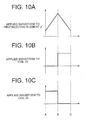
- FIG. 10A , FIG. 10B , and FIG. 10C are diagrams describing driving waveforms of the fourth embodiment
- FIG. 11A , FIG. 11B , and FIG. 11C are diagrams describing a structure of the driving waveforms of the fourth embodiment
- FIG. 12A and FIG. 12B are diagrams showing a structure of a fifth embodiment.
- FIG. 13 is a diagram showing a conventional structure.
- FIG. 1 is a diagram showing a structure of a first embodiment of an inertial drive actuator according to the present invention.
- the first embodiment of the present invention will be described below while referring to the accompanying diagrams.
- FIG. 1 one end of a piezoelectric element 2 is fixed to a fixed member 1 , and the other end thereof is fixed to one end of a vibration substrate 3 .
- a moving body 4 which is movable in a direction of vibration (oscillation) of the piezoelectric element 2 is disposed on the vibration substrate 3 .
- the moving body 4 is formed by an adsorbing portion 4 a , a coil 5 , and a protrusion 7 .
- the protrusion 7 is provided on an opposite side of a surface facing the vibration substrate 3 , of the adsorbing portion 4 a .
- the coil 5 is formed on the projection 7 .
- a driving circuit 20 is connected to each of the piezoelectric element 2 and the coil 5 .
- the piezoelectric element 2 corresponds to a displacement generating means (unit) according to the present invention.
- a fixed substrate 1 or the vibration substrate 3 is made of a magnetic body (such as iron, and magnetic stainless steel), and the adsorbing portion 4 a is also a magnetic body.
- a bottom surface of the adsorbing body 4 a is in a contact with the vibration substrate 3 , and when an electric current is applied to the coil 5 , a magnetic field is generated.
- the magnetic field generated passes through the moving body 4 which is a magnetic body, and a magnetic field is generated also in the adsorbing portion 4 a .
- a magnetic adsorption force is generated with respect to the fixed member 1 or the vibration substrate 3 which is a magnetic body, and the moving body 4 and the vibration substrate 3 make a close contact, and a frictional force is generated between the two.
- FIG. 2A , FIG. 2B , FIG. 3A , and FIG. 3B Driving waveforms of the inertial drive actuator are shown in FIG. 2A , FIG. 2B , FIG. 3A , and FIG. 3B .
- FIG. 2A and FIG. 2B are waveforms when the moving body 4 is moved to right.
- FIG. 3A and FIG. 3B are waveforms when the moving body 4 is moved to left.
- a driving principle will be described below by using FIG. 2A , FIG. 2B , FIG. 3A , and FIG. 3B .
- the piezoelectric element 2 At a portion where a waveform applied to the piezoelectric element 2 rises steeply, the piezoelectric element 2 is extended to be displaced, and is rapidly displaced to left. With the displacement of the piezoelectric element 2 , the vibration substrate 3 is also rapidly displaced to left.
- the piezoelectric element 2 Conversely, at a portion where the waveform applied to the piezoelectric element 2 falls, the piezoelectric element 2 is contracted to be displaced, and the vibration substrate 3 is displaced to right. During this time, the electric current to the coil 5 is stopped. At this time, there is no electromagnetic force between the moving body 4 and the vibration substrate 3 , and an adsorption force, or in other words, the frictional force does not act. Therefore, when the vibration substrate 3 moves to right, the moving body 4 slips with respect to the vibration substrate 3 , and at the same time, remains at that position due to a force of inertia. By repeating this, the moving body 4 moves to left with respect to the vibration substrate 3 .
- the friction being imparted by the magnetic absorption force by allowing to synchronize with the piezoelectric vibrations, since the moving body moves only when the friction has increased, a driving efficiency is improved. Further, since the frictional force is controlled by the magnetic adsorption force generated by the electric current applied to the coil 5 , it does not change due to wearing out. Consequently, a stable operation is possible even when used for a long time.
- FIG. 4 A second embodiment of the present invention is shown in FIG. 4 .
- two adsorbing portions namely a first adsorbing portion 41 a and a second adsorbing portion 41 b are formed on a moving body 41 .
- a coil 51 having an axis in a direction of movement of the moving body 41 is formed between the first adsorbing portion 41 a and the second adsorbing portion 41 b .
- an electric current is applied to the coil 5
- an electric field generated in the coil 51 is generated in the two adsorbing portions namely the first adsorbing portion 41 a and the second adsorbing portion 41 b . Since the magnetic adsorption force is acquired in the first adsorbing portion 41 a and the second adsorbing portion 41 b , even stronger magnetic adsorption force is acquired.
- the axis of the coil 51 by letting the axis of the coil 51 to be in a direction same as the direction of movement of the moving body 41 , and providing two adsorbing portions namely the first adsorbing portion 41 a and the second adsorbing portion 41 b as an adsorbing portion with the vibration substrate 3 , adsorption force sufficient for acquiring the frictional force even upon making small a size is achieved.
- the actuator is made small.
- FIG. 5 shows a third embodiment of the present invention.
- a guide 11 for regulating a movement in a direction perpendicular to the direction of movement of the moving body 41 is provided to the fixed member 1 .
- the guide 11 it is possible to let the direction of movement of the moving body 41 coincide with a direction of vibration of the piezoelectric element 2 , or in other words, with a direction of vibration of the vibration substrate 3 .
- the magnetic adsorption force due to the magnetic field is generated only in the first adsorbing portion 41 a , the second adsorbing portion 41 b , and the vibration substrate 3 , without having an effect of a magnetic field generated by the guide 11 .
- a permanent magnet 6 may be provided on the fixed member 1 at a position facing the vibration substrate 3 .
- FIG. 8 is a diagram in which a modified embodiment of the third embodiment is shown.
- the guide 11 is not provided to the fixed member 1 but to the vibration substrate 3 .
- the vibration substrate 3 By letting the vibration substrate 3 to be a magnetic body, a magnetic field generated in the adsorbing portion 41 is generated not only on a surface facing the vibration substrate 3 but also in the guide 11 , and a magnetic adsorption is developed. Therefore, it is possible to increase an area of magnetic adsorption, and a stable driving is possible even when a size of the actuator is made small.
- FIG. 9 A structure of a fourth embodiment of the present invention is shown in FIG. 9 .
- Driving waveforms of the fourth embodiment are shown in FIG. 10A , FIG. 10B , FIG. 10C , FIG. 11A , FIG. 11B , and FIG. 11C .
- two moving bodies 42 and 43 are disposed to be separated on the vibration substrate 3 .
- As the driving waveforms shown in FIG. 10A , FIG. 10B , and FIG. 10C matching with a time of applying a voltage to the piezoelectric element 2 , an electric current is applied each of a coil 52 and a coil 53 at different timings. By making such an arrangement, it is possible to move one moving body to right and the other moving body to left.
- the two moving bodies 42 and 43 move in the same direction. In this manner, only by changing the timing of the current applied to the coils 52 and 53 of the moving bodies 42 and 43 in one piezoelectric element 2 and the vibration substrate 3 , it is possible to move the two moving bodies 42 and 43 in separate directions or in the same direction without increasing a size of the actuator, mainly in the direction perpendicular to the direction of movement.
- FIG. 12A shows a structure of a fifth embodiment of the present invention and FIG. 12B shows a cross-sectional view thereof along a line A-A.
- a lens L 2 is coupled with the moving body 4 , and the lens L 2 coupled with the moving body 4 is moved.
- An optical system is formed by a lens L 1 and a lens L 3 which are fixed, apart from the lens L 2 , and further, by disposing an image pickup element (not shown in the diagram) toward the lens L 3 , it is possible to build an optical apparatus.
- it is one combination of the moving body 4 and the lens.
- it by increasing the combinations of the moving body 4 and the lens, it possible to realize a zoom and an auto focus etc. by driving multiple groups of lenses.
- a coupled portion with a lens by a protrusion which forms the coil 5 as shown in FIG. 12A and FIG. 12B , it is also possible to make small a lens driving system.
- the inertial drive actuator according to the present invention is useful as an inertial drive actuator which moves a moving member in a predetermined direction by a frictional force between a driving member and the moving member, and is particularly suitable for an inertial drive actuator which necessitates a stable driving velocity (speed) and a position control even when continued to be used for a long time.
- the inertial drive actuator according to the present invention acquires the frictional force necessary for the movement by a magnetic adsorption force, even when used for a long time, there is no decline in the frictional force due to the wearing out of a vibration substrate and an adsorbing portion. Consequently, since there is no decline in the driving velocity and the position control due to the wearing out, even when it is continued to be moved for a long time, an effect is shown that it is possible to drive the moving member with sufficient stability.
Abstract
Description
Claims (21)
Applications Claiming Priority (2)
| Application Number | Priority Date | Filing Date | Title |
|---|---|---|---|
| JP2008-014923 | 2008-01-25 | ||
| JP2008014923A JP5185640B2 (en) | 2008-01-25 | 2008-01-25 | Inertial drive actuator |
Publications (2)
| Publication Number | Publication Date |
|---|---|
| US20090189486A1 US20090189486A1 (en) | 2009-07-30 |
| US7808153B2 true US7808153B2 (en) | 2010-10-05 |
Family
ID=40898496
Family Applications (1)
| Application Number | Title | Priority Date | Filing Date |
|---|---|---|---|
| US12/355,029 Active 2029-04-09 US7808153B2 (en) | 2008-01-25 | 2009-01-16 | Inertial drive actuator |
Country Status (2)
| Country | Link |
|---|---|
| US (1) | US7808153B2 (en) |
| JP (1) | JP5185640B2 (en) |
Cited By (4)
| Publication number | Priority date | Publication date | Assignee | Title |
|---|---|---|---|---|
| US9350222B2 (en) | 2011-11-11 | 2016-05-24 | Olympus Corporation | Inertial drive actuator |
| US9621074B2 (en) | 2011-07-08 | 2017-04-11 | Olympus Corporation | Inertial drive actuator |
| US9621075B2 (en) | 2012-05-01 | 2017-04-11 | Olympus Corporation | Inertial drive actuator |
| US9634550B2 (en) | 2012-05-17 | 2017-04-25 | Olympus Corporation | Inertial drive actuator |
Families Citing this family (4)
| Publication number | Priority date | Publication date | Assignee | Title |
|---|---|---|---|---|
| JP5808000B2 (en) | 2011-07-08 | 2015-11-10 | オリンパス株式会社 | Inertial drive actuator |
| US9691544B2 (en) * | 2011-08-18 | 2017-06-27 | Winchester Technologies, LLC | Electrostatically tunable magnetoelectric inductors with large inductance tunability |
| JP5851210B2 (en) * | 2011-11-11 | 2016-02-03 | オリンパス株式会社 | Inertial drive actuator |
| CN113258825B (en) * | 2021-05-31 | 2022-05-27 | 吉林大学 | Piezoelectric driver control method based on stick-slip and impact principle coupling |
Citations (6)
| Publication number | Priority date | Publication date | Assignee | Title |
|---|---|---|---|---|
| US5589723A (en) * | 1994-03-29 | 1996-12-31 | Minolta Co., Ltd. | Driving apparatus using transducer |
| US6803699B2 (en) * | 2002-08-21 | 2004-10-12 | Minolta Co., Ltd. | Drive mechanism employing electromechanical transducer and drive method therefor |
| US6841899B2 (en) * | 2003-03-31 | 2005-01-11 | Olympus Corporation | Actuator, actuator driving method, and atcuator system |
| US7348693B2 (en) * | 2003-08-06 | 2008-03-25 | Olympus Corporation | Vibration wave linear motor |
| US7550896B1 (en) * | 2008-03-18 | 2009-06-23 | Silicon Touch Technology Inc. | Piezoelectric actuator system with position detection function and method thereof |
| US7608979B2 (en) * | 2005-08-04 | 2009-10-27 | Konica Minolta Holdings, Inc. | Driving device and driving system |
Family Cites Families (7)
| Publication number | Priority date | Publication date | Assignee | Title |
|---|---|---|---|---|
| JPH07274552A (en) * | 1994-04-01 | 1995-10-20 | Nikon Corp | Linear motor |
| JPH08126354A (en) * | 1994-10-20 | 1996-05-17 | Nikon Corp | Precision positioning device |
| JPH11136979A (en) * | 1997-10-28 | 1999-05-21 | Shinko Electric Co Ltd | Inertial drive-type moving unit |
| JP2002315369A (en) * | 2001-04-13 | 2002-10-25 | Nec Corp | Actuator, optical fiber moving body and optical switch |
| JP4716096B2 (en) * | 2005-06-08 | 2011-07-06 | ソニー株式会社 | Driving device and imaging device |
| JP2007129821A (en) * | 2005-11-02 | 2007-05-24 | Olympus Corp | Impact driven actuator and lens driver |
| JP4912728B2 (en) * | 2006-04-12 | 2012-04-11 | オリンパス株式会社 | Inertial drive actuator |
-
2008
- 2008-01-25 JP JP2008014923A patent/JP5185640B2/en active Active
-
2009
- 2009-01-16 US US12/355,029 patent/US7808153B2/en active Active
Patent Citations (7)
| Publication number | Priority date | Publication date | Assignee | Title |
|---|---|---|---|---|
| US5589723A (en) * | 1994-03-29 | 1996-12-31 | Minolta Co., Ltd. | Driving apparatus using transducer |
| US6803699B2 (en) * | 2002-08-21 | 2004-10-12 | Minolta Co., Ltd. | Drive mechanism employing electromechanical transducer and drive method therefor |
| US6841899B2 (en) * | 2003-03-31 | 2005-01-11 | Olympus Corporation | Actuator, actuator driving method, and atcuator system |
| US7348693B2 (en) * | 2003-08-06 | 2008-03-25 | Olympus Corporation | Vibration wave linear motor |
| US7449802B2 (en) * | 2003-08-06 | 2008-11-11 | Olympus Corporation | Vibration wave linear motor |
| US7608979B2 (en) * | 2005-08-04 | 2009-10-27 | Konica Minolta Holdings, Inc. | Driving device and driving system |
| US7550896B1 (en) * | 2008-03-18 | 2009-06-23 | Silicon Touch Technology Inc. | Piezoelectric actuator system with position detection function and method thereof |
Cited By (4)
| Publication number | Priority date | Publication date | Assignee | Title |
|---|---|---|---|---|
| US9621074B2 (en) | 2011-07-08 | 2017-04-11 | Olympus Corporation | Inertial drive actuator |
| US9350222B2 (en) | 2011-11-11 | 2016-05-24 | Olympus Corporation | Inertial drive actuator |
| US9621075B2 (en) | 2012-05-01 | 2017-04-11 | Olympus Corporation | Inertial drive actuator |
| US9634550B2 (en) | 2012-05-17 | 2017-04-25 | Olympus Corporation | Inertial drive actuator |
Also Published As
| Publication number | Publication date |
|---|---|
| JP5185640B2 (en) | 2013-04-17 |
| JP2009177974A (en) | 2009-08-06 |
| US20090189486A1 (en) | 2009-07-30 |
Similar Documents
| Publication | Publication Date | Title |
|---|---|---|
| US7808153B2 (en) | Inertial drive actuator | |
| JP4912728B2 (en) | Inertial drive actuator | |
| JP4804040B2 (en) | Impact drive actuator | |
| US20070096602A1 (en) | Impact drive actuator and lens drive device using the same | |
| US10498261B2 (en) | Vibration-type actuator that moves vibrating body and driven body relatively to each other, and electronic apparatus | |
| CN101662235A (en) | Method of driving a driving apparatus | |
| JP2005057907A (en) | Driving device | |
| JP5490132B2 (en) | Drive device | |
| JPH11356070A (en) | Drive unit using electromechanical transducing element and driving circuit therefor | |
| JP2008197220A (en) | Lens barrel driving device | |
| JPH11356071A (en) | Drive unit using electromechanical transducing element and driving circuit therefor | |
| JP4804037B2 (en) | Impact drive actuator | |
| US9634532B2 (en) | Inertial drive actuator | |
| JP5722145B2 (en) | Inertial drive actuator | |
| JP6659164B2 (en) | Linear drive device, lens barrel, and imaging device | |
| US9385579B2 (en) | Inertial drive actuator | |
| US9350222B2 (en) | Inertial drive actuator | |
| JP2012147510A (en) | Inertial drive actuator | |
| JP2007221988A (en) | Piezoelectric actuator and electronic apparatus using same | |
| JP2019146434A (en) | Vibration wave driven motor and lens driving device | |
| JP5669446B2 (en) | Driving mechanism of moving body | |
| JPS63136111A (en) | Compact actuator | |
| JP2014241697A (en) | Drive device and camera module | |
| JP2005354830A (en) | Control method for actuator | |
| JP2015033181A (en) | Ultrasonic motor and apparatus including the same |
Legal Events
| Date | Code | Title | Description |
|---|---|---|---|
| AS | Assignment |
Owner name: OLYMPUS CORPORATION, JAPAN Free format text: ASSIGNMENT OF ASSIGNORS INTEREST;ASSIGNOR:MATSUKI, KAORU;REEL/FRAME:022121/0102 Effective date: 20090107 |
|
| STCF | Information on status: patent grant |
Free format text: PATENTED CASE |
|
| FEPP | Fee payment procedure |
Free format text: PAYOR NUMBER ASSIGNED (ORIGINAL EVENT CODE: ASPN); ENTITY STATUS OF PATENT OWNER: LARGE ENTITY |
|
| FPAY | Fee payment |
Year of fee payment: 4 |
|
| AS | Assignment |
Owner name: OLYMPUS CORPORATION, JAPAN Free format text: CHANGE OF ADDRESS;ASSIGNOR:OLYMPUS CORPORATION;REEL/FRAME:039344/0502 Effective date: 20160401 |
|
| MAFP | Maintenance fee payment |
Free format text: PAYMENT OF MAINTENANCE FEE, 8TH YEAR, LARGE ENTITY (ORIGINAL EVENT CODE: M1552) Year of fee payment: 8 |
|
| MAFP | Maintenance fee payment |
Free format text: PAYMENT OF MAINTENANCE FEE, 12TH YEAR, LARGE ENTITY (ORIGINAL EVENT CODE: M1553); ENTITY STATUS OF PATENT OWNER: LARGE ENTITY Year of fee payment: 12 |