US7806607B2 - Cylindrical molded article, lens barrel, camera, and injection mold - Google Patents
Cylindrical molded article, lens barrel, camera, and injection mold Download PDFInfo
- Publication number
- US7806607B2 US7806607B2 US12/021,517 US2151708A US7806607B2 US 7806607 B2 US7806607 B2 US 7806607B2 US 2151708 A US2151708 A US 2151708A US 7806607 B2 US7806607 B2 US 7806607B2
- Authority
- US
- United States
- Prior art keywords
- density regions
- cam grooves
- low
- gates
- molded article
- Prior art date
- Legal status (The legal status is an assumption and is not a legal conclusion. Google has not performed a legal analysis and makes no representation as to the accuracy of the status listed.)
- Expired - Fee Related, expires
Links
Images


Classifications
-
- G—PHYSICS
- G02—OPTICS
- G02B—OPTICAL ELEMENTS, SYSTEMS OR APPARATUS
- G02B7/00—Mountings, adjusting means, or light-tight connections, for optical elements
- G02B7/02—Mountings, adjusting means, or light-tight connections, for optical elements for lenses
- G02B7/04—Mountings, adjusting means, or light-tight connections, for optical elements for lenses with mechanism for focusing or varying magnification
- G02B7/10—Mountings, adjusting means, or light-tight connections, for optical elements for lenses with mechanism for focusing or varying magnification by relative axial movement of several lenses, e.g. of varifocal objective lens
- G02B7/102—Mountings, adjusting means, or light-tight connections, for optical elements for lenses with mechanism for focusing or varying magnification by relative axial movement of several lenses, e.g. of varifocal objective lens controlled by a microcomputer
-
- B—PERFORMING OPERATIONS; TRANSPORTING
- B29—WORKING OF PLASTICS; WORKING OF SUBSTANCES IN A PLASTIC STATE IN GENERAL
- B29C—SHAPING OR JOINING OF PLASTICS; SHAPING OF MATERIAL IN A PLASTIC STATE, NOT OTHERWISE PROVIDED FOR; AFTER-TREATMENT OF THE SHAPED PRODUCTS, e.g. REPAIRING
- B29C45/00—Injection moulding, i.e. forcing the required volume of moulding material through a nozzle into a closed mould; Apparatus therefor
- B29C45/0025—Preventing defects on the moulded article, e.g. weld lines, shrinkage marks
-
- G—PHYSICS
- G03—PHOTOGRAPHY; CINEMATOGRAPHY; ANALOGOUS TECHNIQUES USING WAVES OTHER THAN OPTICAL WAVES; ELECTROGRAPHY; HOLOGRAPHY
- G03B—APPARATUS OR ARRANGEMENTS FOR TAKING PHOTOGRAPHS OR FOR PROJECTING OR VIEWING THEM; APPARATUS OR ARRANGEMENTS EMPLOYING ANALOGOUS TECHNIQUES USING WAVES OTHER THAN OPTICAL WAVES; ACCESSORIES THEREFOR
- G03B17/00—Details of cameras or camera bodies; Accessories therefor
- G03B17/02—Bodies
- G03B17/04—Bodies collapsible, foldable or extensible, e.g. book type
-
- B—PERFORMING OPERATIONS; TRANSPORTING
- B29—WORKING OF PLASTICS; WORKING OF SUBSTANCES IN A PLASTIC STATE IN GENERAL
- B29C—SHAPING OR JOINING OF PLASTICS; SHAPING OF MATERIAL IN A PLASTIC STATE, NOT OTHERWISE PROVIDED FOR; AFTER-TREATMENT OF THE SHAPED PRODUCTS, e.g. REPAIRING
- B29C45/00—Injection moulding, i.e. forcing the required volume of moulding material through a nozzle into a closed mould; Apparatus therefor
- B29C45/0025—Preventing defects on the moulded article, e.g. weld lines, shrinkage marks
- B29C2045/0027—Gate or gate mark locations
-
- B—PERFORMING OPERATIONS; TRANSPORTING
- B29—WORKING OF PLASTICS; WORKING OF SUBSTANCES IN A PLASTIC STATE IN GENERAL
- B29L—INDEXING SCHEME ASSOCIATED WITH SUBCLASS B29C, RELATING TO PARTICULAR ARTICLES
- B29L2031/00—Other particular articles
- B29L2031/764—Photographic equipment or accessories
Definitions
- the present invention relates to a cylindrical molded article and an injection mold, and more particularly relates to a cylindrical molded article used in the lens barrel of a camera and an injection mold.
- One conventional type of lens barrel is a multistage retractable lens barrel.
- This kind of lens barrel is made up of a plurality of cylindrical members of different diameter.
- three cam grooves and three cam pins that engage with these cam grooves are provided to a plurality of cylindrical members, for example.
- the cam grooves are usually formed on the inner peripheral part of the cylindrical members.
- An injection molding apparatus mainly includes an injection mold, and an injection apparatus for injecting the molten molding material into the mold.
- the injection apparatus can be adjusted for molding material injection pressure and injection speed.
- the injection mold is provided with a cavity, a sprue, a plurality of runners, and a plurality of gates.
- the cavity is a hollow space used for form a molded article.
- the sprue is a channel through which flows the molding material injected from the injection apparatus.
- the runners guide the molding material from the sprue to the cavity.
- the gates are constrictions for preventing the back-flow of the molding material from the cavity to the runners, and are disposed between the runners and the cavity.
- a plurality of runners are disposed at a constant pitch in the circumferential direction so that the molding material will flow evenly.
- a plurality of gates are also disposed at a constant pitch in the circumferential direction.
- Injection molding mainly includes a temperature adjustment step in which the temperature of the metal mold is adjusted, a filling step in which the mold is filled with the molding material, and a pressure-holding cooling step in which the molded article is cooled inside the mold.
- the pressure-holding cooling step the pressure is held at a specific level by the injection apparatus. This causes molding material to be supplied to portions where heat shrinkage has occurred, and minimizes deformation of the molded article due to heat shrinkage.
- the wall thickness of the cylindrical molded article is uneven because of the cam grooves. Consequently, the thicker and thinner parts cool at different rates in the pressure-holding cooling step, so the heat shrinkage varies from place to place. As a result, there is a decrease in the circularity of the cylindrical molded article, and the cylindrical molded article cannot be obtained as designed. Even though the pressure is maintained in the pressure-holding cooling step, it may be impossible to suppress deformation of the molded article, depending on the shape of the cam grooves.
- the cam grooves will be offset in the radial direction from the designed positioned. As a result, the lens group supported by the plurality of cylindrical molded articles becomes out of position, and this adversely affects the optical performance of the imaging optical system. Also, if the cam grooves become misaligned in the radial direction with respect to the designed position, there will be greater sliding resistance between the cam grooves and the cam pins, which hinders smooth zoom operation. As a result, greater drive force is necessary, and this increases power consumption.
- correction of the injection mold is generally carried out in conventional injection molding. More specifically, with a conventional metal mold design, deformation due to heat shrinkage is predicted on the basis of experimentation or simulation. The mold is produced in the shape of the molded article according to the predicted amount of deformation. Next, a prototype is formed using the mold thus produced. The dimensions of the various parts of the prototype are measured, and the differences between the design and measured values are calculated. Metal mold correction is performed using this dimensional error as an offset value. In the case of cylindrical molded articles used in a lens barrel, the cavity of the mold is formed as a cylindrical hollow space that is not a true circle.
- the main body there is a need in the field of digital cameras for the main body to be as compact as possible to make the product more portable. More specifically, there is a need to reduce the size of the lens barrel, which is considered to be a major factor in obtaining a smaller overall size.
- One way to make a lens barrel smaller is to increase the change ratio of the focal distance in zooming. As this is done, the shape of the cam grooves becomes more complicated, and the difference in the wall thickness of the cylindrical molded articles increases. Consequently, reducing the size of a lens barrel leads to a decrease in dimensional precision in cylindrical molded articles.
- dimensional precision of a cylindrical molded article can be increased by adjusting the gate position according to the shape of a cam groove.
- high-density regions regions where cam grooves are clustered in cylindrical molded articles
- the walls are thinner in these high-density regions than in the surrounding regions, and the flow resistance of the molding material during injection molding is higher in the high-density regions. Accordingly, pressure loss of the molding material is greater in the high-density regions than in the surrounding regions, and the molding material has more difficulty flowing into the high-density regions in the pressure-holding cooling step.
- the molding material tends not to be replenished in an amount corresponding to the heat shrinkage, and deformation due to heat shrinkage in the high-density regions tends not to be suppressed with a conventional cylindrical molded article.
- the heat shrinkage causes the high-density regions to move inward in the radial direction.
- the cylindrical molded article according to a first aspect of the present invention is a cylindrical molded article formed by injection molding, including a cylindrical portion, at least three cam grooves, three first gate portions, and three high-density regions.
- the cam grooves are formed in either the inner peripheral part or the outer peripheral part of the cylindrical portion.
- the first gate portions are formed at an end of the cylindrical portion, and are vestiges of gates in injection molding.
- the high-density regions are regions on the faces where the cam grooves are formed, in which there is the highest proportion of the axial direction dimension accounted for by the three or more cam grooves with respect to the axial direction dimension of the cylindrical portion.
- the first gate portions are disposed closer to one of two adjacent high-density regions than the other of the two adjacent high-density regions in the circumferential direction.
- the first gate portions are vestiges of gates in injection molding, and the positions of the first gates correspond to the positions of gates of the injection mold.
- the gates are portions where the molding material flows from a runner into a cavity in injection molding, and are a portion in which the channel is constricted so that the molding material will not back-flow into the runner in the pressure-holding cooling step.
- the high-density regions are regions where cam grooves are clustered, and are portions where the wall of the cylindrical molded article is thinner. That is, in the high-density regions, the flow resistance of the molding material is higher, and the molding material tends not to flow in.
- An example of the molding material is a thermoplastic resin or other such synthetic resin.
- the first gate portions are disposed at a location closer to the other of the high-density regions. That is, the first gate portions are disposed in the vicinity of the high-density regions. Therefore, in injection molding, the molding material tends to flow into the high-density regions, and in the pressure-holding cooling step, deformation of the cylindrical molded article due to heat shrinkage tends to be suppressed more than in the past. As a result, if the disposition of the first gate portions is given thought at the metal mold design stage, the amount of deformation of a cylindrical molded article formed with an initial mold will be less than in the past, and dimensional precision can be increased without increasing the number of mold corrections. Specifically, with this cylindrical molded article, manufacturing cost can be reduced while dimensional precision is increased.
- the cylindrical molded article according to a second aspect of the present invention is the cylindrical molded article of the first aspect, further including three second gate portions that are formed at an end of the cylindrical portion as vestiges of gates in injection molding.
- the second gate portions are disposed at a location closer to one of two adjacent high-density regions than the other in the circumferential direction of the two adjacent high-density regions.
- the first gate portions and second gate portions are disposed in the vicinity of the high-density regions, and therefore the molding material tends to flow more reliably into the high-density regions, and in the pressure-holding cooling step, deformation of the cylindrical molded article due to heat shrinkage tends to be suppressed better than in the past.
- the second gate portions are vestiges of gates in injection molding, and the locations of the second gates correspond to the locations of the gates of the injection mold.
- the cylindrical molded article according to a third aspect of the present invention is the cylindrical molded article of the second aspect, wherein the first gate portions are disposed at a location closer to one of two adjacent second gate portions than the other in the circumferential direction of the two adjacent second gate portions.
- first gate portions and second gate portions are disposed at a constant pitch in the circumferential direction. This makes it easier to dispose the first gate portions and second gate portions in the vicinity of the high-density regions.
- the cylindrical molded article according to a fourth aspect of the present invention is the cylindrical molded article of the second or third aspects, wherein the high-density regions are disposed in the circumferential direction between the first gate portions and one of two adjacent second gate portions.
- the high-density regions are disposed in a region where the distance between the first gate portions and second gate portions is shorter. Therefore, the molding material flows more readily into the high-density regions.
- the cylindrical molded article according to a fifth aspect of the present invention is the cylindrical molded article of any one of the first to fourth aspects, further including three low-density regions.
- the low-density regions are regions on the faces where the cam grooves are formed, in which there is the lowest proportion of the axial direction dimension accounted for by the three or more cam grooves with respect to the axial direction dimension of the cylindrical portion.
- the first gate portions are disposed at a location closer to the high-density regions than to the low-density regions in the circumferential direction between adjacent high-density regions and low-density regions.
- the low-density regions are regions in which the proportion accounted for by the cam grooves is the lowest, and in which the flow resistance is lower than in the high-density regions, and where the molding material tends to flow in. Therefore, if the first gate portions are moved closer to the high-density regions than to the low-density regions, the molding material will tend to flow into the high-density regions.
- the cylindrical molded article according to a sixth aspect of the present invention is a lens barrel supporting an imaging optical system, including the cylindrical molded article according to any one of the first to fifth aspects and a lens frame.
- the lens group included in the imaging optical system is fixed to the lens frame, which has at least three cam pins that engage with the cam grooves.
- this lens barrel makes use of a cylindrical molded article with improved dimensional precision, the positional precision of the lens group is improved, and the optical performance of the imaging optical system is higher.
- the camera according to a seventh aspect of the present invention includes the lens barrel according to the sixth aspect, an imaging optical system supported by the lens barrel, an imaging unit for capturing an optical image of a subject formed by the imaging optical system, and an outer case supporting the lens barrel.
- the injection mold according to an eighth aspect of the present invention is an injection mold for injection molding a molding material to obtain a cylindrical molded article having at least three cam grooves.
- This injection mold includes a first portion, a second portion, a third portion, and a fourth portion.
- the first portion has a cavity arranged to mold a cylindrical molded article.
- the second portion has a sprue into which the molding material is injected.
- the third portion has three first runners connected to the sprue.
- the fourth portion has three first gates that connect the cavity and the three first runners.
- the high-density regions are regions in which there is the highest proportion of the axial direction dimension accounted for by the portion corresponding to the three or more cam grooves with respect to the axial direction dimension of the cavity.
- the first gates are disposed at a location closer to one of two adjacent high-density regions than the other in the circumferential direction of the two adjacent high-density regions.
- the high-density regions correspond to regions where the cam grooves cluster in the cylindrical molded article. That is, in the high-density regions of the cavity, the flow resistance of the molding material is higher and the molding material tends not to flow in.
- the molding material is a thermoplastic resin or other such synthetic resin.
- the first gates are disposed at a location closer to the other of the high-density regions. That is, the first gates are disposed in the vicinity of the high-density regions. Therefore, in injection molding, the molding material tends to flow into the high-density regions, and in the pressure-holding cooling step, deformation of the cylindrical molded article due to heat shrinkage tends to be suppressed more than in the past. As a result, if the disposition of the first gates is given thought at the metal mold design stage, the amount of deformation of a cylindrical molded article formed with an initial mold will be less than in the past, and dimensional precision can be increased without increasing the number of mold corrections. Specifically, with this injection mold, manufacturing cost can be reduced while dimensional precision is increased.
- the injection mold according to a ninth aspect of the present invention is the injection mold according to the eighth aspect, wherein the third portion further has three second runners connected to the sprue.
- the fourth portion further has three second gates that connect the second runners and the cavity.
- the second gates are disposed at a location closer to one of two adjacent high-density regions than the other in the circumferential direction of the two adjacent high-density regions.
- the first gates and second gates are disposed in the vicinity of the high-density regions, and therefore the molding material tends to flow more reliably into the high-density regions, and in the pressure-holding cooling step, deformation of the cylindrical molded article due to heat shrinkage tends to be suppressed better than in the past.
- the injection mold according to a tenth aspect of the present invention is the injection mold according to the ninth aspect, wherein the first gates are disposed at a location closer to one of two adjacent second gates than the other in the circumferential direction of the two adjacent second gates.
- first gates and second gates are disposed at an irregular pitch, which makes it easier to dispose the first gates and second gates in the vicinity of the high-density regions.
- the injection mold according to an eleventh aspect of the present invention is the injection mold according to the ninth or tenth aspect, wherein the high-density regions are disposed in the circumferential direction between the first gates and the other of the two adjacent second gates.
- the high-density regions are disposed in a region where the distance between the first gate portions and second gate portions is shorter. Therefore, the molding material flows more readily into the high-density regions.
- the injection mold according to a twelfth aspect of the present invention is the injection mold according to any one of the eighth to eleventh aspects, wherein the first portion further has three low-density regions.
- the low-density regions are regions in which there is the lowest proportion of the axial direction dimension accounted for by the portion corresponding to the three or more cam grooves with respect to the axial direction dimension of the cylindrical portion.
- the first gates are disposed at a location closer to the high-density regions than to the low-density regions in the circumferential direction between adjacent high-density regions and low-density regions.
- the low-density regions are regions in which the proportion accounted for by the cam grooves is the lowest, and in which the flow resistance is lower than in the high-density regions, and where the molding material tends to flow in. Therefore, if the first gate portions are moved closer to the high-density regions than to the low-density regions, the molding material will tend to flow into the high-density regions.
- FIG. 1 is a schematic perspective view of a digital camera
- FIG. 2 is a schematic perspective view of a digital camera
- FIG. 3 is an exploded perspective view of a lens barrel
- FIGS. 4A and 4B are schematic diagrams of a molded article and an injection mold
- FIG. 5 is a detail view of the area around the gate portions
- FIG. 6 is a development view of the inner peripheral side of a drive frame
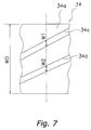
- FIG. 7 is a diagram of the method for determining the high-density regions and low-density regions.
- FIGS. 8A and 8B are comparative diagrams of prior art and the present invention.
- FIGS. 1 and 2 are schematic perspective views of the digital camera 1 .
- FIG. 1 shows the situation when a lens barrel 3 is in an image capture state.
- the digital camera 1 is a camera for acquiring an image of a subject.
- a multistage retractable lens barrel 3 is installed in the digital camera 1 in order to afford higher magnification and a more compact size.
- the six sides of the digital camera 1 are defined as follows.
- the side that faces the subject when an image is captured with the digital camera 1 is called the front face, and the opposite side is called the rear face.
- the front face The side that faces the subject when an image is captured with the digital camera 1
- the opposite side is called the rear face.
- the left face the side of the camera that is to the left when viewed from the subject side
- the opposite side is called the right face.
- FIG. 1 is a perspective view of the front, top, and left faces.
- the six sides of the various constituent members disposed in the digital camera 1 are similarly defined. That is, the above definitions apply to the six sides of the various constituent members when they have been disposed in the digital camera 1 .
- FIG. 1 there is defined a three-dimensional coordinate system (right-hand system) having a Y axis that is parallel to the optical axis A of an imaging optical system O (discussed below).
- the direction from the rear face side toward the front face side along the optical axis A is the Y axis positive direction
- the direction from the right face side toward the left face side perpendicular to the optical axis A is the X axis positive direction
- the direction from the bottom face side toward the top face side perpendicular to the X and Y axes is the Z axis positive direction.
- the digital camera 1 mainly includes an outer case 2 that holds the various units, an imaging optical system O that forms an optical image of the subject, and a lens barrel 3 that movably supports the imaging optical system O.
- the imaging optical system O is made up of a plurality of lens groups, and these lens groups are disposed in a state of being aligned in the Y axis direction.
- the lens barrel 3 has a multistage retractable configuration, and is supported by the outer case 2 .
- the plurality of lens groups are supported by the lens barrel 3 to be relatively movable in the Y axis direction.
- the configuration of the lens barrel 3 will be described in detail below.
- a CCD unit 21 serving as an imaging unit that subjects optical images to photoelectric conversion, and an image storing unit 16 that stores the images acquired by the CCD unit 21 are built into the outer case 2 .
- a liquid crystal monitor 15 for displaying the images acquired by the CCD unit 21 is provided to the rear face of the outer case 2 .
- a shutter release button 11 , a control dial 12 , a power switch 13 , and a zoom adjustment lever 14 are provided to the top face of the outer case 2 so that the user can capture images and perform other such operations.
- the shutter release button 11 is a button for inputting the exposure timing.
- the control dial 12 is a dial for making various settings related to image capture.
- the power switch 13 is used to switch the digital camera 1 on and off.
- the zoom adjustment lever 14 is used to adjust the zoom magnification, and can rotate over a specific angle range around the shutter release button 11 .
- FIGS. 1 and 2 show only the main configuration of the digital camera 1 , and therefore components other than those discussed above may be provided to the digital camera 1 .
- FIG. 3 is an exploded perspective view of the lens barrel 3 .
- the lens barrel 3 mainly includes a base plate 31 fixed to the outer case 2 , a zoom motor 32 fixed to the base plate 31 and serving as a drive source, a stationary frame 33 that holds various frame members between itself and the base plate 31 , a drive frame 34 to which the drive force of the zoom motor 32 is inputted, and a straight-movement frame 35 that is supported by the stationary frame 33 to be relatively movable in the Y axis direction.
- a CCD sensor 22 of the CCD unit 21 is attached to the base plate 31 .
- An example of the zoom motor 32 is a stepping motor.
- the lens barrel 3 further includes a first lens frame 36 that supports a first lens group G 1 , a second lens frame 37 that supports a second lens group G 2 , and a third lens frame 38 that supports a third lens group G 3 .
- the first lens group G 1 is, for example, a lens group having negative power overall, and takes in light from the subject.
- the second lens group G 2 is, for example, a lens group having positive power overall.
- the third lens group G 3 is, for example, a lens group having positive power for adjusting the focal point.
- the imaging optical system O is made up of the first lens group G 1 , the second lens group G 2 , and the third lens group G 3 .
- the stationary frame 33 is a member for guiding the drive frame 34 , and makes up a member on the stationary side of the lens barrel 3 along with the base plate 31 .
- the stationary frame 33 is fixed by screws to the base plate 31 .
- the stationary frame 33 mainly includes a stationary frame main body 33 a that makes up the main part, and a drive gear 33 b that is rotatably supported by the stationary frame main body 33 a.
- the stationary frame main body 33 a is fixed to the base plate 31 , and the drive frame 34 is disposed inside the inner periphery thereof.
- the drive gear 33 b is a member for transmitting the drive force of the zoom motor 32 to the drive frame 34 , and meshes with a gear (not shown) of the zoom motor 32 .
- Three cam grooves 33 c for guiding the drive frame 34 , and three straight-movement grooves 33 d for guiding the straight-movement frame 35 are formed on the inner peripheral part of the stationary frame main body 33 a .
- the cam grooves 33 c are spaced equally in the circumferential direction.
- the straight-movement grooves 33 d extend in the Y axis direction, and are spaced equally in the circumferential direction.
- the drive frame 34 is a member for guiding the first lens frame 36 and the second lens frame 37 , and is disposed inside the inner periphery of the stationary frame 33 .
- the drive frame 34 mainly includes a substantially cylindrical drive frame main body 34 a that is disposed inside the inner periphery of the stationary frame main body 33 a.
- Three cam pins 43 are provided as cam members on the outer peripheral part of the drive frame main body 34 a , and three first cam grooves 34 c and three second cam grooves 34 d are formed on the inner peripheral part.
- the first cam grooves 34 c are grooves for guiding the first lens frame 36 .
- the second cam grooves 34 d are grooves for guiding the second lens frame 37 .
- the three first cam grooves 34 c are spaced equally in the circumferential direction.
- the three second cam grooves 34 d are spaced equally in the circumferential direction.
- the three cam pins 43 are spaced equally in the circumferential direction, and engage with the three cam grooves 33 c of the stationary frame 33 . That is, the drive frame 34 is supported by the stationary frame 33 via the cam pins 43 .
- a gear portion 34 e is formed on the outer peripheral part of the drive frame main body 34 a .
- the gear portion 34 e meshes with the drive gear 33 b of the stationary frame 33 .
- the drive force of the zoom motor 32 is transmitted through the drive gear 33 b to the drive frame 34 .
- the drive frame 34 is driven around the optical axis A (the R 1 direction and the R 2 direction) by the drive force of the zoom motor 32 .
- the drive frame 34 is driven to the R 1 side by the zoom motor 32 .
- the cam pins 43 move along the cam grooves 33 c of the stationary frame 33
- the drive frame 34 moves to the Y axis direction positive side relative to the stationary frame 33 .
- the drive frame 34 is driven to the R 2 side by the zoom motor 32 .
- the drive frame 34 moves to the Y axis direction negative side relative to the stationary frame 33 .
- the drive frame 34 is movable in the Y axis direction while rotating relative to the stationary frame 33 , according to the shape of the cam grooves 33 c.
- the straight-movement frame 35 is a member for preventing the rotation of the first lens frame 36 relative to the stationary frame 33 , and is disposed inside the inner periphery of the drive frame 34 .
- the straight-movement frame 35 mainly includes a cylindrical straight-movement frame main body 35 a and three straight-movement pins 35 b formed on the outer peripheral part of the straight-movement frame main body 35 a.
- the straight-movement pins 35 b are disposed on the Y axis direction negative side of the straight-movement frame main body 35 a so as not to interfere with the drive frame 34 , and engage with the straight-movement grooves 33 d in the stationary frame 33 . That is, the straight-movement frame 35 is supported by the stationary frame 33 to be relatively straight movable in the Y axis direction.
- a bayonet groove 35 e is formed on the outer peripheral part of the straight-movement frame main body 35 a .
- a bayonet tab 34 f (not shown) formed on the inner peripheral part of the drive frame 34 engages with the bayonet groove 35 e . This allows the straight-movement frame 35 to rotate relative to the drive frame 34 and to move integrally in the Y axis direction.
- the straight-movement frame 35 moves along with the drive frame 34 in the Y axis direction without rotating relative to the stationary frame 33 (while rotating relative to the drive frame 34 ).
- Three first guide grooves 35 c and three second guide grooves 35 d that extend in the Y axis direction are formed in the straight-movement frame main body 35 a .
- the three first guide grooves 35 c are spaced equally in the circumferential direction, and the three second guide grooves 35 d are spaced equally in the circumferential direction.
- Cam pins 36 b (discussed below) of the first lens frame 36 are inserted in the first guide grooves 35 c .
- Cam pins 37 b (discussed below) of the second lens frame 37 are inserted in the second guide grooves 35 d . That is, the rotation of the first lens frame 36 and the second lens frame 37 relative to the stationary frame 33 is restricted by the straight-movement frame 35 . Furthermore, movement of the first lens frame 36 and the second lens frame 37 in the Y axis direction is not restricted by the first guide grooves 35 c and the second guide grooves 35 d.
- the first lens frame 36 is a member supporting the first lens group G 1 to be relatively movable in the Y axis direction, and is disposed inside the inner periphery of the straight-movement frame 35 .
- the first lens frame 36 mainly includes a first lens frame main body 36 a in the interior of which is held the first lens group G 1 , and the three cam pins 36 b provided on the outer peripheral part of the first lens frame main body 36 a .
- the cam pins 36 b are passed through the first guide grooves 35 c and engage with the first cam grooves 34 c of the drive frame 34 .
- the cam pins 36 b move along the first cam grooves 34 c .
- the movement of the cam pins 36 b in the rotary direction here is restricted by the first guide grooves 35 c of the straight-movement frame 35 . Therefore, the cam pins 36 b move only in the Y axis direction along the first cam grooves 34 c and the first guide grooves 35 c .
- the first lens frame 36 is movable in the Y axis direction relative to the drive frame 34 according to the shape of the first cam grooves 34 c , without rotating relative to the stationary frame 33 .
- the second lens frame 37 is a member supporting the second lens group G 2 to be relatively movable in the Y axis direction, and is disposed inside the inner periphery of the straight-movement frame 35 and on the Y axis direction negative side of the first lens frame 36 .
- the second lens frame 37 mainly includes a first frame 50 and second frame 59 in the interior of which is held the second lens group G 2 , and the three cam pins 37 b provided on the outer peripheral part of the first frame 50 .
- the cam pins 37 b are passed through the second guide grooves 35 d and engage with the second cam grooves 34 d of the drive frame 34 .
- the cam pins 37 b move along the second guide grooves 35 d .
- the movement of the cam pins 37 b here in the rotational direction is restricted by the second guide grooves 35 d of the straight-movement frame 35 . Therefore, just as with the first lens frame 36 , the cam pins 37 b move only in the Y axis direction along the second cam grooves 34 d and the second guide grooves 35 d.
- the second lens frame 37 is movable in the Y axis direction relative to the drive frame 34 according to the shape of the second cam grooves 34 d , without rotating relative to the stationary frame 33 .
- the third lens frame 38 is a member supporting the third lens group G 3 to be relatively movable in the Y axis direction, and is supported by focus shafts 31 a and 31 b of the base plate 31 to be relatively movable in the Y axis direction.
- the third lens frame 38 is driven by a focus motor 39 fixed to the base plate 31 .
- the focus motor 39 moves the third lens frame 38 in the Y axis direction relative to the base plate 31 .
- the first lens frame 36 and the second lens frame 37 can be moved in the direction along the optical axis A by the zoom motor 32 via the stationary frame 33 , the drive frame 34 , and the straight-movement frame 35 .
- the third lens frame 38 can be moved in the direction along the optical axis A by the focus motor 39 .
- this configuration results in a retractable lens barrel 3 that allows adjustment of the focus and the zoom magnification of the imaging optical system O.
- FIGS. 4A and 4B are schematic diagrams of a molded article 80 and an injection mold 70 .
- FIG. 4A is a schematic perspective view of the molded article 80 and the injection mold 70
- FIG. 4B is a plan view of the molded article 80 as seen in the axial direction.
- the molded article 80 is made from a synthetic resin removed from the mold 70 after injection molding.
- Example of the synthetic resin is a polycarbonate or other such a thermoplastic resin.
- the molded article 80 mainly includes the drive frame 34 (as a cylindrical molded article) and a channel portion 81 .
- the channel portion 81 is cut off of the drive frame 34 after injection molding.
- a total of six cam grooves (the first cam grooves 34 c and the second cam grooves 34 d ) are formed on the inner peripheral part of the drive frame 34 .
- the channel portion 81 is a portion formed by a channel in the injection mold 70 during injection molding, and includes a sprue portion 82 , three first runner portions 84 a linked to the sprue portion 82 , three first gate portions 84 b , three second runner portions 85 a linked to the sprue portion 82 , and three second gate portions 85 b .
- the first gate portions 84 d and second gate portions 85 b are disposed on an annular end face formed in the drive frame 34 and directed to the axial direction.
- the channel portion 81 has six gate portions (the first gate portions 84 d and second gate portions 85 b ).
- the injection mold 70 is a metal mold used for injection molding, and mainly includes a first portion 71 , a second portion 72 , a third portion 73 , and a fourth portion 79 .
- the mold 70 is made up of a plurality of parts, but the first portion 71 to the fourth portion 79 are divided in the sense of being portions having different functions. Therefore, the portions 71 to 73 and 79 are not limited to being made up of different parts.
- a cavity 71 a for forming the drive frame 34 is formed in the first portion 71 .
- the cavity 71 a is defined by combining two mold parts (not shown), for example.
- the drive frame 34 is molded in the cavity 71 a.
- the sprue 72 a is defined by a cylindrical sprue bush (not shown).
- the sprue portion 82 is molded in the sprue 72 a.
- Three first runners 74 a and three second runners 75 a that are connected to the sprue 72 a are formed in the third portion 73 .
- Three first gates 74 b and three second gates 75 b are formed in the fourth portion 79 .
- One end of the first runners 74 a is connected to the sprue 72 a , and the other end is connected to the first gates 74 b .
- One end of the second runners 75 a is connected to the sprue 72 a , and the other end is connected to the second gates 75 b .
- the first runner portions 84 a and the second runner portions 85 a are molded in the first runners 74 a and the second runners 75 a
- the first gate portions 84 b and the second gate portions 85 b are molded in the first gates 74 b and the second gates 75 b.
- FIG. 5 is a detailed diagram of the area around the gate portions.
- the first gate portions 84 b and the second gate portions 85 b are vestiges of the first gates 74 b and the second gates 75 b during injection molding, and after the channel portion 81 is cut off, these are included in part of the drive frame 34 .
- An annular portion 34 f whose walls are thinner than those of the drive frame main body 34 a is formed at the end of the drive frame main body 34 a on the Y axial direction positive side.
- Three first recesses 84 c and three second recesses 85 c are formed in the annular portion 34 f .
- First protrusions 84 d extend in the axial direction from the first recesses 84 c .
- Second protrusions 85 d extend in the axial direction from the second recesses 85 c .
- the first protrusions 84 d and the second protrusions 85 d are held in the axial direction in the first recesses 84 c and the second recesses 85 c.
- the first protrusions 84 d and second protrusions 85 d may not remain.
- the first gate portions 84 b are made up of the first recesses 84 c
- the second gate portions 85 b are made up of the second recesses 85 c.
- the drive frame 34 is characterized by the disposition of the first gate portions 84 b and the second gate portions 85 b .
- the disposition of the first gate portions 84 b and the second gate portions 85 b will be described through reference to FIG. 6 .
- FIG. 6 is a development view of the inner peripheral side of the drive frame 34 .
- the disposition will be described using the constitution of the molded article 80 , but since the constitution of the molded article 80 corresponds to the constitution of the metal mold 70 , the following description can be considered to apply to the mold 70 as well, and not just to the molded article 80 .
- the three first gate portions 84 b are disposed at a constant pitch in the circumferential direction, and the three second gate portions 85 b are disposed at a constant pitch in the circumferential direction.
- the first gate portions 84 b and the second gate portions 85 b are disposed at an irregular pitch.
- each of the first gate portions 84 b is disposed at a location closer to the R 2 -side second gate portion 85 b (the other second gate portion) than to the R 1 -side second gate portion 85 b (the one second gate portion).
- the distance L 1 between the first gate portion 84 b and the R 1 -side second gate portion 85 b (the other second gate portion) in the circumferential direction is shorter than the distance L 2 between the first gate portion 84 b and the R 2 -side second gate portion 85 b (the one second gate portion).
- the angle ⁇ 1 between the first gate portion 84 b and the R 1 side second gate portion 85 b is smaller than the angle ⁇ 2 between the first gate portion 84 b and the R 2 -side second gate portion 85 b .
- the distances L 1 and L 2 and the angles ⁇ 1 and ⁇ 2 are based on the center of each part in the circumferential direction.
- the three first cam grooves 34 c and the three second cam grooves 34 d are formed on the inner peripheral part of the drive frame 34 .
- the three first cam grooves 34 c all have the same shape and are disposed at a constant pitch in the circumferential direction.
- the three second cam grooves 34 d all have the same shape and are disposed at a constant pitch in the circumferential direction.
- the first cam grooves 34 c and the second cam grooves 34 d are alternately disposed in the circumferential direction so as not to cross each other.
- the first cam grooves 34 c each include a first cam groove main body C 2 and a first conducting groove C 3 formed at one end of the first cam groove main body C 2 .
- the first conducting groove C 3 extends in the axial direction, and passes through the end of the drive frame main body 34 a .
- the other end C 1 of the first cam groove main body C 2 does not pass through in the axial direction.
- the second cam grooves 34 d each include a second cam groove main body D 2 , a second conducting groove D 1 formed at one end of the second cam groove main body D 2 , and a third conducting groove D 3 formed at the other end of the second cam groove main body D 2 .
- the second conducting groove D 1 and the third conducting groove D 3 extend in the axial direction, and pass through the end of the drive frame main body 34 a.
- first cam grooves 34 c have the same width from the end C 1 to the first conducting groove C 3 .
- the second cam grooves 34 d have the same width from the second conducting groove D 1 to the third conducting groove D 3 .
- first cam grooves 34 c and the second cam grooves 34 d have the same width.
- the drive frame 34 does not have a constant wall thickness because of the first cam grooves 34 c and the second cam grooves 34 d . More specifically, on the inner peripheral face of the drive frame 34 there are three high-density regions H in which the proportion accounted for by the cam grooves is highest, and three low-density regions L in which the proportion accounted for by the cam grooves is lowest.
- the three high-density regions H are disposed at a constant pitch in the circumferential direction.
- the three low-density regions L are disposed at a constant pitch in the circumferential direction.
- the high-density regions H are regions in which there is the highest proportion of the axial direction dimension accounted for by the first cam grooves 34 c and the second cam grooves 34 d with respect to the axial direction dimension of the drive frame 34 , on the inner peripheral face of the drive frame 34 .
- the low-density regions L are regions in which there is the lowest proportion of the axial direction dimension accounted for by the first cam grooves 34 c and the second cam grooves 34 d with respect to the axial direction dimension of the drive frame 34 , on the inner peripheral face of the drive frame 34 .
- the high-density regions H coincide with the region in which the third conducting groove D 3 extends in the axial direction.
- the low-density regions L coincide with the region in which the first cam grooves 34 c and the second cam grooves 34 d extend in the circumferential direction.
- the clusters of lines where the proportion P is highest are the high-density regions H, and the clusters of lines where the proportion P is lowest are the low-density regions L.
- the first gate portions 84 b and the second gate portions 85 b are disposed in the vicinity of the high-density regions H. More specifically, the first gate portions 84 b are disposed between the high-density regions H and the low-density regions L in the circumferential direction. The first gate portions 84 b are disposed at a location closer to the high-density regions H than to the low-density regions L. The second gate portions 85 b are disposed between the high-density regions H and the low-density regions L in the circumferential direction. The second gate portions 85 b are disposed at a location closer to the high-density regions H than to the low-density regions L.
- the distance L 3 between the first gate portions 84 b and the high-density regions H in the circumferential direction is less than the distance L 4 between the first gate portions 84 b and the low-density regions L.
- the distance L 5 between the second gate portions 85 b and the high-density regions H in the circumferential direction is less than the distance L 6 between the second gate portions 85 b and the low-density regions L.
- the distance L 3 between the first gate portions 84 b and the high-density regions H is less than the distance L 5 between the second gate portions 85 b and the high-density regions H.
- the distances L 3 to L 6 are based on the center of each part in the circumferential direction.
- the first gate portions 84 b are disposed at a location corresponding to a thick portion E 1 formed between the end C 1 of the first cam grooves 34 c and the second cam groove main body D 2 in the circumferential direction.
- the result is that the molding material that flows from the first gate portions 84 b (more specifically, the first gates 74 b ) passes between the end C 1 and the second cam groove main body D 2 , which increases the fluidity of the molding material.
- gates are disposed predominantly in the vicinity of the high-density regions H, and therefore even if the flow resistance of the molding material is high, the pressure of the molding material in the vicinity of the high-density regions H will rise, making it easy for the molding material to flow into the high-density regions H.
- the drive frame 34 is driven by the zoom motor 32 by a specific angle to the R 1 side relative to the stationary frame 33 .
- the drive frame 34 moves to the Y axis direction positive side relative to the stationary frame 33 while rotating relative to the stationary frame 33 according to the shape of the cam grooves 33 c.
- the first lens frame 36 and the second lens frame 37 move along with the drive frame 34 to the Y axis direction positive side relative to the stationary frame 33 .
- the first lens frame 36 and the second lens frame 37 do not rotate relative to the stationary frame 33 at this point.
- the first lens frame 36 and the second lens frame 37 move along with the drive frame 34 to the Y axis direction positive side while moving in the Y axis direction relative to the drive frame 34 according to the shape of the first cam grooves 34 c and the second cam grooves 34 d .
- the first lens frame 36 and the second lens frame 37 move relatively in the Y axis direction.
- the first lens frame 36 and the second lens frame 37 move in the Y axis direction relative to the stationary frame 33 by an amount that is larger (or smaller) than the amount of movement of the drive frame 34 in the Y axis direction.
- the drive frame 34 is driven by the zoom motor 32 to the R 1 side relative to the stationary frame 33 , according to the rotational angle and operation duration of the zoom adjustment lever 14 .
- the drive frame 34 , the first lens frame 36 , and the second lens frame 37 move together to the Y axis direction positive side relative to the stationary frame 33 , and the zoom magnification of the imaging optical system O is increased.
- the drive frame 34 is driven by the zoom motor 32 to the R 2 side relative to the stationary frame 33 , according to the rotational angle and operation duration of the zoom adjustment lever 14 .
- the drive frame 34 , the first lens frame 36 , and the second lens frame 37 move together to the Y axis direction negative side relative to the stationary frame 33 , and the zoom magnification of the imaging optical system O is decreased.
- the first gate portions 84 b and the second gate portions 85 b are disposed at an irregular pitch so that the first gate portions 84 b and the second gate portions 85 b will be closer to the high-density regions H. Therefore, the pressure of the molding material in the vicinity of the high-density regions H in injection molding can be higher than in the past, and the molding material will readily flow into the high-density regions H in injection molding. As a result, there tends to be less deformation of the molded article 80 (more specifically, the drive frame 34 (cylindrical molded article)) caused due to heat shrinkage in the pressure-holding cooling step than in the past.
- FIG. 8A is a comparative diagram of the circularity
- FIG. 8B is a comparative graph of the maximum amount of deviation in circularity.
- the “conventional” molded article refers to one in which six gates are disposed at a constant pitch. These data are the result of measuring the actual dimensions of the molded articles.
- the gate locations are predominantly disposed in the vicinity of the high-density regions H, which reduces the maximum amount of deviation in circularity to about one-third, and improves circularity. It can be seen from the above results that the gate locations employed in the molded article 80 and the injection mold 70 are effective.
- the amount of deformation of the cylindrical molded article formed in the initial metal mold 70 is smaller than with the conventional molded article, and dimensional precision can be increased without increasing the number of mold corrections. That is, with this molded article 80 , dimensional precision can be increased while the manufacturing cost is lowered.
- the first gate portions 84 b and the second gate portions 85 b are disposed at a location closer to the high-density regions H than to the low-density regions L, and therefore the molding material flows even more readily into the high-density regions H.
- the drive frame 34 or other such molded article 80 with increased dimensional precision is used for this lens barrel 3 , and therefore the positional precision of the lens group is higher and the optical performance of the imaging optical system O can be improved. Also, with this digital camera 1 , since the optical performance of the imaging optical system O is higher, the quality of an acquired image is improved.
- cylindrical molded article, lens barrel, camera, and injection mold according to the present invention are not limited to the above embodiment, and various modifications and alterations are possible without departing from the gist of the present invention.
- first gate portions 84 b and the second gate portions 85 b were provided at a total of six places, but the number of gate portions is not limited to this, and the present invention can be applied to cases when there are more or fewer than six gate portion locations.
- the cam grooves were formed on the inner peripheral part of the drive frame 34 , but the present invention can also be applied when the cam grooves are formed on the outer peripheral part, or when the cam grooves are formed on both the inner peripheral part and the outer peripheral part. Also, the number, shape, disposition, and so forth of the cam grooves are not limited to the embodiment given above.
- the gate portions were formed on the end face of the drive frame 34 in the axial direction, but the disposition of the gate portions is not limited to this.
- gate portions may be provided on the inner peripheral side or the outer peripheral side of the drive frame 34 .
- the high-density regions H and the low-density regions L were regions having a certain surface area, but are not limited to this.
- the high-density regions H and the low-density regions L may instead be lines extending in the axial direction.
- Conceivable devices in which the above-mentioned lens barrel 3 is installed include digital cameras that allow moving or still pictures to be captured, film cameras that make use of silver halide film, and so forth. In any case, the effect will be the same as that in the embodiments given above.
- the term “configured” as used herein to describe a component, section or part of a device includes hardware and/or software that is constructed and/or programmed to carry out the desired function.
- the term “comprising” and its derivatives, as used herein, are intended to be open ended terms that specify the presence of the stated features, elements, components, groups, integers, and/or steps, but do not exclude the presence of other unstated features, elements, components, groups, integers and/or steps.
- the foregoing also applies to words having similar meanings such as the terms, “including”, “having” and their derivatives.
- the terms “part,” “section,” “portion,” “member” or “element” when used in the singular can have the dual meaning of a single part or a plurality of parts.
Landscapes
- Physics & Mathematics (AREA)
- General Physics & Mathematics (AREA)
- Engineering & Computer Science (AREA)
- Manufacturing & Machinery (AREA)
- Mechanical Engineering (AREA)
- General Engineering & Computer Science (AREA)
- Optics & Photonics (AREA)
- Lens Barrels (AREA)
- Moulds For Moulding Plastics Or The Like (AREA)
Abstract
Description
Claims (20)
Applications Claiming Priority (2)
| Application Number | Priority Date | Filing Date | Title |
|---|---|---|---|
| JP2007-018405 | 2007-01-29 | ||
| JP2007018405A JP5049605B2 (en) | 2007-01-29 | 2007-01-29 | Cylindrical molded products, lens barrels, cameras and injection molds |
Publications (2)
| Publication Number | Publication Date |
|---|---|
| US20080181602A1 US20080181602A1 (en) | 2008-07-31 |
| US7806607B2 true US7806607B2 (en) | 2010-10-05 |
Family
ID=39668102
Family Applications (1)
| Application Number | Title | Priority Date | Filing Date |
|---|---|---|---|
| US12/021,517 Expired - Fee Related US7806607B2 (en) | 2007-01-29 | 2008-01-29 | Cylindrical molded article, lens barrel, camera, and injection mold |
Country Status (2)
| Country | Link |
|---|---|
| US (1) | US7806607B2 (en) |
| JP (1) | JP5049605B2 (en) |
Cited By (3)
| Publication number | Priority date | Publication date | Assignee | Title |
|---|---|---|---|---|
| US8840326B2 (en) * | 2012-09-17 | 2014-09-23 | Samsung Electronics Co., Ltd. | Lens barrel assembly and photographing apparatus including the same |
| US10843424B2 (en) | 2016-02-26 | 2020-11-24 | Foundation For Research And Business, Seoul National University Of Science And Technology | Lens injection molded product to which hot runner is applied |
| US11106019B2 (en) | 2018-07-12 | 2021-08-31 | Largan Digital Co., Ltd. | Plastic barrel, autofocus module and electronic device |
Families Citing this family (2)
| Publication number | Priority date | Publication date | Assignee | Title |
|---|---|---|---|---|
| JP6565190B2 (en) * | 2015-01-08 | 2019-08-28 | ニプロ株式会社 | Blood device cap and blood device |
| CN112342043B (en) * | 2020-10-21 | 2022-03-29 | 安徽科技学院 | Biochar preparation equipment |
Citations (11)
| Publication number | Priority date | Publication date | Assignee | Title |
|---|---|---|---|---|
| US4826424A (en) * | 1985-09-25 | 1989-05-02 | Canon Kabushiki Kaisha | Lens barrel made by injection molding |
| JPH06347687A (en) | 1993-06-07 | 1994-12-22 | Nikon Corp | Zoom lens barrel |
| JPH08227637A (en) | 1994-02-23 | 1996-09-03 | Matsushita Electric Works Ltd | Control switch and manufactur thereof |
| JP2995509B2 (en) | 1990-09-21 | 1999-12-27 | アネルバ株式会社 | Thin film making method |
| US20010017735A1 (en) | 2000-02-01 | 2001-08-30 | Asahi Kogaku Kogyo Kabushiki Kaisha | Cam mechanism for driving a linearly-guided lens |
| US6424469B2 (en) | 2000-02-10 | 2002-07-23 | Canon Kabushiki Kaisha | Lens barrel |
| JP2002370268A (en) | 2001-06-15 | 2002-12-24 | Olympus Optical Co Ltd | Cylindrical molding and method for deciding shape of cylindrical molding |
| US6567222B2 (en) | 2001-02-05 | 2003-05-20 | Fuji Photo Optical Co., Ltd. | Lens barrel for use in zoom lens apparatus |
| JP3523249B1 (en) | 2003-07-31 | 2004-04-26 | 株式会社双信 | Method of manufacturing cylinder with cam groove and cylinder with cam groove manufactured by this method |
| US20040156127A1 (en) | 2003-02-04 | 2004-08-12 | Pentax Corporation | Cam mechanism of a lens barrel |
| JP2005308843A (en) | 2004-04-19 | 2005-11-04 | Sony Corp | Retractable lens barrel and imaging device |
Family Cites Families (6)
| Publication number | Priority date | Publication date | Assignee | Title |
|---|---|---|---|---|
| JPS61110522A (en) * | 1984-11-06 | 1986-05-28 | Olympus Optical Co Ltd | Hollow and cylindrical molding frame body |
| JPS62131216A (en) * | 1985-12-03 | 1987-06-13 | Canon Inc | Lens barrel parts |
| JPH06238711A (en) * | 1993-02-12 | 1994-08-30 | Olympus Optical Co Ltd | Injection molding method and device for plastic |
| JP3459128B2 (en) * | 1995-01-18 | 2003-10-20 | 日本電産コパル株式会社 | Method of forming lens barrel and lens barrel |
| JP3773168B2 (en) * | 2001-04-12 | 2006-05-10 | ポリプラスチックス株式会社 | Cylindrical injection mold, molding method and molded product |
| JP2007015291A (en) * | 2005-07-08 | 2007-01-25 | Olympus Imaging Corp | Cylindrical component |
-
2007
- 2007-01-29 JP JP2007018405A patent/JP5049605B2/en not_active Expired - Fee Related
-
2008
- 2008-01-29 US US12/021,517 patent/US7806607B2/en not_active Expired - Fee Related
Patent Citations (12)
| Publication number | Priority date | Publication date | Assignee | Title |
|---|---|---|---|---|
| US4826424A (en) * | 1985-09-25 | 1989-05-02 | Canon Kabushiki Kaisha | Lens barrel made by injection molding |
| JP2995509B2 (en) | 1990-09-21 | 1999-12-27 | アネルバ株式会社 | Thin film making method |
| JPH06347687A (en) | 1993-06-07 | 1994-12-22 | Nikon Corp | Zoom lens barrel |
| JPH08227637A (en) | 1994-02-23 | 1996-09-03 | Matsushita Electric Works Ltd | Control switch and manufactur thereof |
| US5639403A (en) | 1994-02-23 | 1997-06-17 | Matsushita Electric Works, Ltd. | Method of molding a resin article with an embedded workpiece |
| US20010017735A1 (en) | 2000-02-01 | 2001-08-30 | Asahi Kogaku Kogyo Kabushiki Kaisha | Cam mechanism for driving a linearly-guided lens |
| US6424469B2 (en) | 2000-02-10 | 2002-07-23 | Canon Kabushiki Kaisha | Lens barrel |
| US6567222B2 (en) | 2001-02-05 | 2003-05-20 | Fuji Photo Optical Co., Ltd. | Lens barrel for use in zoom lens apparatus |
| JP2002370268A (en) | 2001-06-15 | 2002-12-24 | Olympus Optical Co Ltd | Cylindrical molding and method for deciding shape of cylindrical molding |
| US20040156127A1 (en) | 2003-02-04 | 2004-08-12 | Pentax Corporation | Cam mechanism of a lens barrel |
| JP3523249B1 (en) | 2003-07-31 | 2004-04-26 | 株式会社双信 | Method of manufacturing cylinder with cam groove and cylinder with cam groove manufactured by this method |
| JP2005308843A (en) | 2004-04-19 | 2005-11-04 | Sony Corp | Retractable lens barrel and imaging device |
Cited By (4)
| Publication number | Priority date | Publication date | Assignee | Title |
|---|---|---|---|---|
| US8840326B2 (en) * | 2012-09-17 | 2014-09-23 | Samsung Electronics Co., Ltd. | Lens barrel assembly and photographing apparatus including the same |
| US10843424B2 (en) | 2016-02-26 | 2020-11-24 | Foundation For Research And Business, Seoul National University Of Science And Technology | Lens injection molded product to which hot runner is applied |
| US11106019B2 (en) | 2018-07-12 | 2021-08-31 | Largan Digital Co., Ltd. | Plastic barrel, autofocus module and electronic device |
| US11828922B2 (en) | 2018-07-12 | 2023-11-28 | Largan Digital Co., Ltd. | Plastic barrel, autofocus module and electronic device |
Also Published As
| Publication number | Publication date |
|---|---|
| US20080181602A1 (en) | 2008-07-31 |
| JP2008185727A (en) | 2008-08-14 |
| JP5049605B2 (en) | 2012-10-17 |
Similar Documents
| Publication | Publication Date | Title |
|---|---|---|
| US7800837B2 (en) | Cylindrical molded article, lens barrel, camera, and injection mold | |
| US7471473B2 (en) | Lens support structure, lens barrel, and camera | |
| US7920345B2 (en) | Lens barrel supporting frame, lens retaining structure, lens barrel and camera | |
| US6424469B2 (en) | Lens barrel | |
| US7806607B2 (en) | Cylindrical molded article, lens barrel, camera, and injection mold | |
| US10054760B2 (en) | Zoom lens barrel and optical apparatus using the same | |
| US8247048B2 (en) | Cylindrical molded article, injection mold and manufacturing method of cylindrical molded article | |
| US7035019B2 (en) | Lens barrel extending and retracting mechanisms | |
| US8308378B2 (en) | Barrier apparatus and image pickup apparatus | |
| US9720205B2 (en) | Lens barrel | |
| US8885266B2 (en) | Lens barrel | |
| US20150098012A1 (en) | Light quantity control apparatus, optical apparatus and image pickup apparatus | |
| JPH08211271A (en) | Lens barrel and optical equipment using the same | |
| US9158085B2 (en) | Lens barrel | |
| US8896933B2 (en) | Lens barrel | |
| JP2004042127A (en) | Lens-barrel | |
| US9007705B2 (en) | Lens barrel | |
| US20080013190A1 (en) | Structure of cam barrel for zoom lens | |
| JP4354574B2 (en) | Zoom lens barrel | |
| JPH11194256A (en) | Zoom lens barrel | |
| JPH11194254A (en) | Zoom lens barrel | |
| US9235024B2 (en) | Lens barrel | |
| JP2000275501A (en) | Lens barrel | |
| JP2869751B2 (en) | Floating mechanism of zoom lens | |
| JP2000199842A (en) | Lens barrel |
Legal Events
| Date | Code | Title | Description |
|---|---|---|---|
| AS | Assignment |
Owner name: MATSUSHITA ELECTRIC INDUSTRIAL CO., LTD., JAPAN Free format text: ASSIGNMENT OF ASSIGNORS INTEREST;ASSIGNORS:IYODA, MAKOTO;NAKAO, SUGURU;REEL/FRAME:021001/0844 Effective date: 20080118 |
|
| AS | Assignment |
Owner name: PANASONIC CORPORATION, JAPAN Free format text: CHANGE OF NAME;ASSIGNOR:MATSUSHITA ELECTRIC INDUSTRIAL CO., LTD.;REEL/FRAME:021897/0516 Effective date: 20081001 Owner name: PANASONIC CORPORATION,JAPAN Free format text: CHANGE OF NAME;ASSIGNOR:MATSUSHITA ELECTRIC INDUSTRIAL CO., LTD.;REEL/FRAME:021897/0516 Effective date: 20081001 |
|
| STCF | Information on status: patent grant |
Free format text: PATENTED CASE |
|
| FEPP | Fee payment procedure |
Free format text: PAYOR NUMBER ASSIGNED (ORIGINAL EVENT CODE: ASPN); ENTITY STATUS OF PATENT OWNER: LARGE ENTITY |
|
| FPAY | Fee payment |
Year of fee payment: 4 |
|
| MAFP | Maintenance fee payment |
Free format text: PAYMENT OF MAINTENANCE FEE, 8TH YEAR, LARGE ENTITY (ORIGINAL EVENT CODE: M1552) Year of fee payment: 8 |
|
| FEPP | Fee payment procedure |
Free format text: MAINTENANCE FEE REMINDER MAILED (ORIGINAL EVENT CODE: REM.); ENTITY STATUS OF PATENT OWNER: LARGE ENTITY |
|
| LAPS | Lapse for failure to pay maintenance fees |
Free format text: PATENT EXPIRED FOR FAILURE TO PAY MAINTENANCE FEES (ORIGINAL EVENT CODE: EXP.); ENTITY STATUS OF PATENT OWNER: LARGE ENTITY |
|
| STCH | Information on status: patent discontinuation |
Free format text: PATENT EXPIRED DUE TO NONPAYMENT OF MAINTENANCE FEES UNDER 37 CFR 1.362 |
|
| FP | Lapsed due to failure to pay maintenance fee |
Effective date: 20221005 |