US780418A - Apparatus for delivering towels and soap. - Google Patents
Apparatus for delivering towels and soap. Download PDFInfo
- Publication number
- US780418A US780418A US21184504A US1904211845A US780418A US 780418 A US780418 A US 780418A US 21184504 A US21184504 A US 21184504A US 1904211845 A US1904211845 A US 1904211845A US 780418 A US780418 A US 780418A
- Authority
- US
- United States
- Prior art keywords
- towel
- soap
- coin
- towels
- lever
- Prior art date
- Legal status (The legal status is an assumption and is not a legal conclusion. Google has not performed a legal analysis and makes no representation as to the accuracy of the status listed.)
- Expired - Lifetime
Links
Images


Classifications
-
- A—HUMAN NECESSITIES
- A47—FURNITURE; DOMESTIC ARTICLES OR APPLIANCES; COFFEE MILLS; SPICE MILLS; SUCTION CLEANERS IN GENERAL
- A47K—SANITARY EQUIPMENT NOT OTHERWISE PROVIDED FOR; TOILET ACCESSORIES
- A47K10/00—Body-drying implements; Toilet paper; Holders therefor
- A47K10/24—Towel dispensers, e.g. for piled-up or folded textile towels; Toilet-paper dispensers; Dispensers for piled-up or folded textile towels provided or not with devices for taking-up soiled towels as far as not mechanically driven
Definitions
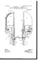
- Figure 1- is an outside front elevation of a machine constructed in accordance with the invention.
- Fig. 2 is an end view thereof.
- Fig. 4 is a view of the back of the door which carries the supply of clean towels and the operating mechanism for feeding them forward for use.
- Fig. 5 is an end view of one of the towel-rods and a clean towel carried thereon.
- Fig. 6 is a sectional view, on an enlarged scale, through the line A B, Fig. 4, looking in the direction of the arrow.
- Fig. 7 is an end view, similarly enlarged-looking in the direction of the arrow marked C, Fig. 4.
- Fig. 8 is a view at right angles to Fig. 7.
- Fig. 9 is an end view looking in the direction of the arrow D, Fig. 4.
- Figs. 10 to 17 are detail parts.
- Fig. 18 shows an end elevation with a reservoir for tablets of soap and the means whereby the tablets can be singly fed forward out of the machine for use.
- Fig. 19 is a view .at right angles to Fig. 18.
- Fig. 19 is a view .at
- - 20 is asectional elevation of a coin-box which is adapted to resist fraudulent attempts to remove the contained coin.
- Fig. 21 is a plan -view thereof; Fig. 22, an end view with the lid On Sheet 2, Fig. 3is a sectional end open; Fig. 23, a section on the line E F, Fig. 21, looking in the direction of the arrow.
- the back of the door 0 of the casing cl is provided with grooved castings c a, down which grooves the towelrods a can fall by gravity.
- the castings e e are spaced apart and stifl'ened or supportedby a cross-stay K. It must be imagined that each towel-rod a carries its folded towel, as in Fig. 5.
- the cavity or recess at the back of the grooves carrying the towel-rods a' may -be masked by a sheet of thin metal f.
- the front of the doorc is provided with a mirror g for use when making the toilet.
- the grooves in the castings e are closed at the bottom by means of disks 7a, provided with a number of notches, into one of which notches or recesses the first towel-rod of the series is disposed, as shown in Fig. 6.
- Means are provided, actuated by the coin mechanism, to partially rotatethe disks, so that the towel-rod a occupying the gaps is ejected and falls by gravity down the inclined surface 2', through a slot in the front of the door a,
- the disks are provided with siX rotation of the notched notches or gaps, so that the coin-actuated l form a gap, and the end of the lever 1' is armechanism is arranged to rotate the disks ranged opposite to this gap, (shown in dotted one-sixth of a revolution each time it is l lines in Fig. 13,) so that when there is no coin brought into action.
- the slide has no elfecton theleverraml mounted upon a shaft Zn, provided at each end its connected parts.
- the platform 4. forms with a ratchet-wheel Z m.
- a pivoted pawl at engages with the ratchet-wheel m and is held in contact by a spring 0.
- This pawl allows the ratchet-wheel m to revolve in the proper direction, but prevents any backward movement, and is used solely as a locking-pawl or detent.
- the ratchet-wheel Z on the other end of the shaft is rotated in the required direction by means of a pawl p, actuated by a link 1 and pivoted lever r.
- This pivoted lever is turned on its fulcrum 8 against the action of a spring t by the coin mechanism, as will be explained, and by means of the connectinglink (1 slides the pawl over one teeth of the ratchet-wheel Z.
- the spring 25 returns the lever to its normal position with a jerk, and the pawl 12 on such backward movement rotates the ratchet-wheels Zm, and with them the shaft is and the notched disks h, a sixth of a revolution, sufiiciently to forcibly eject the first towel-rod of the series, as described.
- the pawl 2 may be of any suitable construction, the one shown in Figs. 15 to 17 being found very efiicient. This consists of a boss u, loosely mounted on the shaft 7r, having a finger between which and a coverplate 4) slides a tooth 10 against the action of a spring .20. In Fig. 15 the cover-plate e is re moved to show the teeth 21), which is guided between projections H, formed on the finger, the spring w being compressed when the tooth is pushed upward between a fixed part y and the part 2 of the tooth.
- Fig. 17 is an end view of the pawl with the cover-plate e in position.
- the coin mechanism to effect the required movement of the lever r is asfollows:
- the front of the apparatus is provided with a slide 2, which can be thrust inward against the action of a spring 3.
- the slide is supported and guided by a platform 4:, and within the interior of the casing the slide is provided with a circular recess 5 to accommodate a coin or coins of the required value.
- the coin plate or slide2 and supporting-platform i are shown in plan view in Figs. 13 and 14:.
- the front part of the slide 2 is cut away to part of a plate 6.
- the protruding end 10 of the slide is preferably provided with a suitable instruction, such as the word Push, and the front of the plate could also hear an announcement as to the value of the coin to be inserted in the slot.
- the towel-rod a bearing its clean towel, in its descent of the inclined surfaces i at each side of the castings a first comes into contact with a pivoted finger 15, which is turned on its fulcrum to allow the rod to pass, and then falls upon and depresses the loaded pivoted finger 16 in its passage to the brackets (1, as shown in dotted lines.
- the pivoted lingers 15 and 16 are arranged on each side of the grooved castings a and are designed to prevent the lifting of either end of the towel-rod a when in the brack ts e to any extent with a view to fraudulently removing the towel-rod and its attached towel out of the casing. ⁇ Vhen the towel has been used, the rod a. is pushed out of the brackets G, over a roller 17, and into the interiorof the casing, as is shown in dotted lines in Fig. 6.
- a hinged door 18, held by an interior catch or bolt 19, is provided. This door can be unfastened from the inside when the locked door 0 has been opened. llf desired, a separate lock and key for the door 18 may be provided. hileans are also provided for indicating when the supply of clean towels is exhausted. This is done conveniently by an aperture 20, formed in plate (3 of the coin mechanism in the front of the casing, backed by a drop-shutter21 bearing the words Full and Empty or other suitable Wording. The shutter is normally raised in the position shown in Fig. 7 to display the word Full by means of a pivoted loaded lever 22, which is maintained in the position shown in Figs.
- the lowest of the series of soap wafers 26 rests upon a platform 27
- the shaft 70 upon which are mounted the notched disks in and which is rotated by the coin mechanism, as described, is provided with a star-wheel 28, which is rotated with the shaft a sixth of a revolution every time the mechanism is operated to procure a clean towel.
- the star-wheel 28 is in contact with and vibrates a pivoted lever 29 against a spring 30, and a pusher 31, loosely pivoted to the end of the lever 29, thrusts the lowest tablet of soap outthrough an aperture 32 in the door 0 upon a table 33 outside the 1 door 0, from'which it may be removed by the person paying for the clean towel.
- the spring v3O returns the lever 29 and pusher 31 into their normal positions.
- Aweight35 may be placed on the top of the soap tablets to prevent them sticking to the receptacle 25 and insure their being fed in turn to the pusher 31.
- the coin or coins after operating the mechanism drop upon a fiat inclined plate 34, Figs. 3 and 4, which is curved at its end to direct the coins through an aperture in the locked box 13 into a special coin-receiver 36 contained in the box and which is separately illustrated in Figs. 20 to 23.
- the coin-receiver 36 is provided with a hinged lid 37, having an eye 38 on the lid and another eye, 39, carried by a pivoted hasp 40.
- the lid can be sealed by means of a cord or tape 41 and a seal 42, which prevents the opening of the lid unless the cordis cut or the seal is broken.
- the coin-receiver is delivered empty and sealed to the collector, whose duty it is to lock it into the box 13 of the apparatus, removing the previous box, which he is bliged to deliver up with the seal unbroken.
- the coin-receiver 36 is formed with an aperture 43, down which the coins fall after operating the coin mechanism. This aperture leads to an inclined chute 44 within the box, upon which rests a pivoted plate 45. The coin in its passage turns the plate on its pivots and falls into the box.
- the plate 45 as shown in dottedlines in Fig. 20, is prevented from opening any more than will just pass the coin by a cross-bar 46. The plate 45 thus practically blocks up the chute and resists any attempt to abstract coins either by shaking the box when inverted or by the insertion of a tool.
- An apparatus for delivering clean towels provided with a number of towel-rods each carrying a towel threaded thereon, grooves or guides in the interior of a suitable casing down which the towel-rods slide by gravity 5 with means for releasing and feeding each towel-rod singly into fixed cups or brackets which serve to prevent the removal of the towel-rods and attached towels out of the casingv and guides to direct the towel-rod when thrust out of the brackets into the interior of the casing, substantially as described.
- An apparatus for delivering clean towels and soap provided with a number of towelrods each carrying a towel threaded thereon, grooves or guides in the interior of a suitable casing down which the towel-rods slide by gravity, a receptacle within the interior of the casing containing wafers or tablets of soap, 1 and means for releasing and feeding each towel-rod singly into cups or'brackets so as to protrude the towel out of the casing together with means for simultaneously delivering a tablet of soap substantially as described.
- cups or brackets to receive each towel-rod as 5 it is fed forward and so protrude the end of the towel out of the casing, and guides to direct the rod and the used towel into the interior of the casing, substantially as described.
- the means for rotating the shaft carrying the notched disks consisting of a pivoted lever vi-' brated to bring a pawl behind a tooth, of a ratchet-wheel on the shaft, and a spring to efiect the reverse movement of the pawl-andratchet wheel to rotate the shaft with a jerk and expel the towel-rod out of the notched disks, together with means for preventing the removal of the towel-rods out of the casing and for locking the shaft so as to prevent reverse movement thereof, substantially as described and shown.
- JosHUA ENTWISLE ALFRED YATES.
Description
, PATENTED JAN. 17, 1905. GARLIGK & A. J. JACKSON.
APPARATUS FOR DELIVERING TOWBLS AND SOAP;-
APPLICATION FILED JUNE 9. 1904.
7 SHEET88HEBT 1.
INVENTORS Lwk. JIM. ll-7 mnes g'aokarw WITNESSES J31. his 13301- No. 780,418. 'PATENTED JAN. 17, 1905.
W. GARLIGK & A. J. JACKSON. 7 APPARATUS FOR DELIVERING TOWELS AND SOAP! APPLICATION TILED JUNE 9, 1904.
'7 SHEETSBHBET 2.
luvtuToks I mums-4mm a.
' luvsuros 606M, 0'
PATBNTED JAN. 17, 1905.
W. GARLIGK & A. J. JACKSON.
APPLIOATIOK FILED JUNE 9, 1904.
APPARATUS FORYDELIVERING TOWELS AND SOAP-.15
- No. 780,418; I 'PATENTED JAN. 17, 1905.
. W. GARLIGK &- A. J. JACKSON. 1 1 APPARATUS FOR DELIVERING TOWELS AND soAP'."
APPLICATION rum) mm: o. 1904. i '1 sums-sum 4.
F102 r/ cs.
No. 780,418. I PATENTED JAN. 17, 1905. W. GARLIOK & A. J. JACKSON. APPARATUS FOR DELIVERING TOWBLS AND SOAP APPLICATION FILED JUNE 9,1904.
7 SHEETS-SHEET 5.
WiTNESSES INVENTOFKS.
acksaw No. 780,418. I 'PATENTED JAN. 17, 1905, Y W. GARLIGK & A. J. JACKSON.
APPARATUS FOR DELIVERING TOWELS AND SOAP;-
APPLIOATION FILED JUNE 9, 1904.
7 SHEETS-SHEET 6.
FIG. /8.- FIG /9.
28 III? IN VENTOR,
Arthur James $5.1; 115 on By Ms filltam 55 WITNESSES.
No. 780,418. PATENTED JAN. 17, 1905; W. GARLICK & A. J. JACKSON. APPARATUS FOR DELIVERING TOWELS AND soAP;
APPLICATION FILED JUNE 9. 1904.
v SHEETS-#8331111.
1NVENTOR elevation.
Patented January 1'7, 1905.
UNITED STATES PATENT OFFICE.
WILLIAMv GARLIOK AND ARTHUR J. JACKSON, OF ASHTON -ON-MERSEY,
. ENGLAND.
APPARATUS FOR DELIVERING TOWELS AND SOAP- SPEOIFICATION forming part of Letters Patent No. 780,418, dated. January 17, 1905. Application filedJ'une 9,1904. Serial No- 211,845.
To all whom it may concern:
Be it known that we, WILLIAM GARLIoK. gentleman, resldlng at Heathfield, Ashton-on -Mersey, and ARTHUR JAMEs J AOKSON, manufacturer, residing at Glenroy, Ashton-on-Mersey, in the county of Chester, England, sub-- 'jects of the King of Great Britain and Ireland, have invented a certain new and useful Apparatus for Delivering Towels and Soap, (for whichwe have made applications for patents tablet of soap therewith on prepayment of a coin or coins.
During thecourse of the following description to render the invention more clear of comprehension reference will be made to the accompanying drawings, in Which On Sheet 1, Figure 1- is an outside front elevation of a machine constructed in accordance with the invention. Fig. 2 is an end view thereof.
Fig. 4 is a view of the back of the door which carries the supply of clean towels and the operating mechanism for feeding them forward for use. Fig. 5 is an end view of one of the towel-rods and a clean towel carried thereon. On Sheet 3, Fig. 6 is a sectional view, on an enlarged scale, through the line A B, Fig. 4, looking in the direction of the arrow. Fig. 7 is an end view, similarly enlarged-looking in the direction of the arrow marked C, Fig. 4. On Sheet 4, Fig. 8 is a view at right angles to Fig. 7. Fig. 9 is an end view looking in the direction of the arrow D, Fig. 4. On Sheet 5, Figs. 10 to 17 are detail parts. On Sheet 6, Fig. 18 shows an end elevation with a reservoir for tablets of soap and the means whereby the tablets can be singly fed forward out of the machine for use. Fig. 19 is a view .at right angles to Fig. 18. On Sheet 7, Fig.
- 20 is asectional elevation of a coin-box which is adapted to resist fraudulent attempts to remove the contained coin. Fig. 21 is a plan -view thereof; Fig. 22, an end view with the lid On Sheet 2, Fig. 3is a sectional end open; Fig. 23, a section on the line E F, Fig. 21, looking in the direction of the arrow.
In carrying the invention into eiiect a number of rods a are used, carrying towels b threaded thereon, to effect which a small loop is formed on one end of the towel, into which loop the rod (4 is inserted. As the towels would tend to obscure the mechanical parts of the machine, they are omitted from the drawings, the rods (0 alone being shown, except in the case of the first towel of the series, which is shown ready for use outside the casing of the apparatus. To begin with, each towel before being placed in the machine is folded over the rod to reduce its length, as shown in Fig. 5, the end of the towel being arranged toward the front of the casing. The back of the door 0 of the casing cl is provided with grooved castings c a, down which grooves the towelrods a can fall by gravity. The castings e e are spaced apart and stifl'ened or supportedby a cross-stay K. It must be imagined that each towel-rod a carries its folded towel, as in Fig. 5. The cavity or recess at the back of the grooves carrying the towel-rods a'may -be masked by a sheet of thin metal f. The front of the doorc is provided with a mirror g for use when making the toilet.
The grooves in the castings e are closed at the bottom by means of disks 7a, provided with a number of notches, into one of which notches or recesses the first towel-rod of the series is disposed, as shown in Fig. 6. Means are provided, actuated by the coin mechanism, to partially rotatethe disks, so that the towel-rod a occupying the gaps is ejected and falls by gravity down the inclined surface 2', through a slot in the front of the door a,
into cups or brackets G, secured to the front of the door 0, when the folded-over end of the towel is protruded out. of the slot, as shown in Figs. 1 and 6. By pulling on this end the full length of the-towel can be withdrawn for use, as shown in Fig. 2. The back of the slot 1' is masked by aplate J, loosely hung on the shaft 70. The notched disks it have then been rotated sufficiently to bring. the next notch in the series. to receive another towel-rod. For instance, the disks are provided with siX rotation of the notched notches or gaps, so that the coin-actuated l form a gap, and the end of the lever 1' is armechanism is arranged to rotate the disks ranged opposite to this gap, (shown in dotted one-sixth of a revolution each time it is l lines in Fig. 13,) so that when there is no coin brought into action.
To effect this partial i in the recess in the slide 2 the inward move.-
disks it, they are mentot the slide has no elfecton theleverraml mounted upon a shaft Zn, provided at each end its connected parts. The platform 4. forms with a ratchet-wheel Z m. A pivoted pawl at engages with the ratchet-wheel m and is held in contact by a spring 0. This pawl allows the ratchet-wheel m to revolve in the proper direction, but prevents any backward movement, and is used solely as a locking-pawl or detent. The ratchet-wheel Z on the other end of the shaft is rotated in the required direction by means of a pawl p, actuated by a link 1 and pivoted lever r. This pivoted lever is turned on its fulcrum 8 against the action of a spring t by the coin mechanism, as will be explained, and by means of the connectinglink (1 slides the pawl over one teeth of the ratchet-wheel Z. On the lever 0' being released by the coin mechanism the spring 25 returns the lever to its normal position with a jerk, and the pawl 12 on such backward movement rotates the ratchet-wheels Zm, and with them the shaft is and the notched disks h, a sixth of a revolution, sufiiciently to forcibly eject the first towel-rod of the series, as described.
The pawl 2 may be of any suitable construction, the one shown in Figs. 15 to 17 being found very efiicient. This consists of a boss u, loosely mounted on the shaft 7r, having a finger between which and a coverplate 4) slides a tooth 10 against the action of a spring .20. In Fig. 15 the cover-plate e is re moved to show the teeth 21), which is guided between projections H, formed on the finger, the spring w being compressed when the tooth is pushed upward between a fixed part y and the part 2 of the tooth. Fig. 17 is an end view of the pawl with the cover-plate e in position. As the pawl is rotated toward the front of the door 0 by the lever 7 and link (1 the spring-tooth is pushed inward when riding over the ratchet-tooth, as shown in Fig. 11, and is again thrust out by the spring w when it has cleared the tooth, as shown in Fig. 12, so as to enable the pawl to rotate the ratchet-wheel to the extent of one teeth by means of the pull of the spring Z, acting on the lever 1', when the lever is released by-the coin mechanism.
The coin mechanism to effect the required movement of the lever r is asfollows: The front of the apparatus is provided with a slide 2, which can be thrust inward against the action of a spring 3. The slide is supported and guided by a platform 4:, and within the interior of the casing the slide is provided with a circular recess 5 to accommodate a coin or coins of the required value. The coin plate or slide2 and supporting-platform i are shown in plan view in Figs. 13 and 14:. The front part of the slide 2 is cut away to part of a plate 6. secured to the door 0 of the casing (Z, and this plate has a coin-slot 7, the coin 8, or coins where more than one is used, after being inserted in the slot being guided by the curved plate 9 to fall flat in the recess in the slide 2. The protruding end 10 of the slide is preferably provided with a suitable instruction, such as the word Push, and the front of the plate could also hear an announcement as to the value of the coin to be inserted in the slot.
On pushing the slide 2 inward the edge of the coin 8 comes into contact with the end of the lever 1', operating the pawl p, turning the lever sulficiently on its pivot to cause the tooth w of the pawl p to ride up and over one of the teeth of the ratchet Z, as shown in Figs. 11 and 12. To prevent the coin 8 from slipping off the end of the lever 1', a projection or ledge 11 is formed on the lever. By the time the lever has been vibrated sufiiciently to bring the spring-tooth w behind a tooth on the ratchet-wheel Z the coin drops off the edge of the supporting-platform, as shown in Fig. 12, and the lever resiles abruptly by the pull of the spring 6, the coin falling down the guiding-plate 12 into a suitable receptacle 13, Fig. 3. Directions'are provided on a tablet 1 1 on the front of the casing to instruct users in the proper working of the apparatus.
The towel-rod a, bearing its clean towel, in its descent of the inclined surfaces i at each side of the castings a first comes into contact with a pivoted finger 15, which is turned on its fulcrum to allow the rod to pass, and then falls upon and depresses the loaded pivoted finger 16 in its passage to the brackets (1, as shown in dotted lines. The pivoted lingers 15 and 16 are arranged on each side of the grooved castings a and are designed to prevent the lifting of either end of the towel-rod a when in the brack ts e to any extent with a view to fraudulently removing the towel-rod and its attached towel out of the casing. \Vhen the towel has been used, the rod a. is pushed out of the brackets G, over a roller 17, and into the interiorof the casing, as is shown in dotted lines in Fig. 6.
. To facilitate the removal of the towel-rods with their attached dirty towels from the bottom of the casing (Z, a hinged door 18, held by an interior catch or bolt 19, is provided. This door can be unfastened from the inside when the locked door 0 has been opened. llf desired, a separate lock and key for the door 18 may be provided. hileans are also provided for indicating when the supply of clean towels is exhausted. This is done conveniently by an aperture 20, formed in plate (3 of the coin mechanism in the front of the casing, backed by a drop-shutter21 bearing the words Full and Empty or other suitable Wording. The shutter is normally raised in the position shown in Fig. 7 to display the word Full by means of a pivoted loaded lever 22, which is maintained in the position shown in Figs. 6 and 7 by means of the towel-rods a bearing on the head 23 of the lever. On the last of the towelrods falling out of the notched disks it the loaded lever 22 drops, allowing the shutter 21 to fall, which not only brings the inscription Empty in front of the slot 20, but also blocks up the slot 7 by means of the tongue 24, as shown in dotted lines in Fig. 7. The front view of the shutter 21, showing two tablets for inscriptions, isshown in Fig. 10.
When it is desired to deliver with the clean towel a small wafer or tablet of soap, we pro'-. vide a casing or receptacle 25 for the required number of soap tablets 26. This receptacle is secured to the inside of the door 0 of the casing d at the side opposite to the coin mechanism and which is marked with the arrow D, Fig. 4, suitable space being provided to ac commodate the soap-receptacle. The arrangement is shown in Figs. 18 and 19. The lowest of the series of soap wafers 26 rests upon a platform 27 The shaft 70, upon which are mounted the notched disks in and which is rotated by the coin mechanism, as described, is provided with a star-wheel 28, which is rotated with the shaft a sixth of a revolution every time the mechanism is operated to procure a clean towel. The star-wheel 28 is in contact with and vibrates a pivoted lever 29 against a spring 30, and a pusher 31, loosely pivoted to the end of the lever 29, thrusts the lowest tablet of soap outthrough an aperture 32 in the door 0 upon a table 33 outside the 1 door 0, from'which it may be removed by the person paying for the clean towel. The spring v3O returns the lever 29 and pusher 31 into their normal positions. Aweight35 may be placed on the top of the soap tablets to prevent them sticking to the receptacle 25 and insure their being fed in turn to the pusher 31. The coin or coins after operating the mechanism drop upon a fiat inclined plate 34, Figs. 3 and 4, which is curved at its end to direct the coins through an aperture in the locked box 13 into a special coin-receiver 36 contained in the box and which is separately illustrated in Figs. 20 to 23.
The coin-receiver 36 is provided with a hinged lid 37, having an eye 38 on the lid and another eye, 39, carried by a pivoted hasp 40. The lid can be sealed by means of a cord or tape 41 and a seal 42, which prevents the opening of the lid unless the cordis cut or the seal is broken. The coin-receiver is delivered empty and sealed to the collector, whose duty it is to lock it into the box 13 of the apparatus, removing the previous box, which he is bliged to deliver up with the seal unbroken.
The coin-receiver 36 is formed with an aperture 43, down which the coins fall after operating the coin mechanism. This aperture leads to an inclined chute 44 within the box, upon which rests a pivoted plate 45. The coin in its passage turns the plate on its pivots and falls into the box. The plate 45, as shown in dottedlines in Fig. 20, is prevented from opening any more than will just pass the coin by a cross-bar 46. The plate 45 thus practically blocks up the chute and resists any attempt to abstract coins either by shaking the box when inverted or by the insertion of a tool.
We declare that what we claim is- 1. An apparatus for delivering clean towels, provided with a number of towel-rods each carrying a towel threaded thereon, grooves or guides in the interior of a suitable casing down which the towel-rods slide by gravity 5 with means for releasing and feeding each towel-rod singly into fixed cups or brackets which serve to prevent the removal of the towel-rods and attached towels out of the casingv and guides to direct the towel-rod when thrust out of the brackets into the interior of the casing, substantially as described.
2. An apparatus for delivering clean towels and soap provided with a number of towelrods each carrying a towel threaded thereon, grooves or guides in the interior of a suitable casing down which the towel-rods slide by gravity, a receptacle within the interior of the casing containing wafers or tablets of soap, 1 and means for releasing and feeding each towel-rod singly into cups or'brackets so as to protrude the towel out of the casing together with means for simultaneously delivering a tablet of soap substantially as described.
3. In apparatus for delivering clean towels, the provision of a number of towels carried by rods arranged to fall by gravity in grooves or guides, notched disksfor retaining such rods, the means for partially rotating such notched disks to feed the towel-rods singly consisting I of a pawl engaging with a ratchet-wheel on the shaft carrying the notched disks, a pivoted lever-and link to actuate the pawl in one direction and a spring in the other direction,
cups or brackets to receive each towel-rod as 5 it is fed forward and so protrude the end of the towel out of the casing, and guides to direct the rod and the used towel into the interior of the casing, substantially as described.
4. In combination, in apparatus for deliv- I20 ering clean towels and soap therewith, a plurality of towels carried by rods arranged to fall by gravity in grooves or guides, notched disks for retaining such rods, means for partially rotating such notched disks to feed the 5 towel-rods singly consisting of a pawl engaging with a ratchet-wheel on the shaft carrying the notched disks, the pivoted lever and link to actuate the pawl in one direction, and a spring in the reverse d rection, cups or 3 brackets to receive each towel-rod as it is fed forward to protrude the end of the towel out of the casing, guides to direct the used towel into the interior of the casing, a receptacle for the tablets of soap, a lever actuating a pusher bearing against the lowest tablet of soap and a rotatable star-wheel vibrating the lever to eject the tablet of soap out of the casing, substantially as described.
5. In apparatus of the indicated nature, the means for rotating the shaft carrying the notched disks consisting of a pivoted lever vi-' brated to bring a pawl behind a tooth, of a ratchet-wheel on the shaft, and a spring to efiect the reverse movement of the pawl-andratchet wheel to rotate the shaft with a jerk and expel the towel-rod out of the notched disks, together with means for preventing the removal of the towel-rods out of the casing and for locking the shaft so as to prevent reverse movement thereof, substantially as described and shown.
In witness whereof \vehave hereunto set our hands in presence of two witnesses.
\VI LLI AM GA RLIOK. ARTHUR J. JACKSON. Witnesses:
JosHUA ENTWISLE, ALFRED YATES.
Priority Applications (1)
| Application Number | Priority Date | Filing Date | Title |
|---|---|---|---|
| US21184504A US780418A (en) | 1904-06-09 | 1904-06-09 | Apparatus for delivering towels and soap. |
Applications Claiming Priority (1)
| Application Number | Priority Date | Filing Date | Title |
|---|---|---|---|
| US21184504A US780418A (en) | 1904-06-09 | 1904-06-09 | Apparatus for delivering towels and soap. |
Publications (1)
| Publication Number | Publication Date |
|---|---|
| US780418A true US780418A (en) | 1905-01-17 |
Family
ID=2848902
Family Applications (1)
| Application Number | Title | Priority Date | Filing Date |
|---|---|---|---|
| US21184504A Expired - Lifetime US780418A (en) | 1904-06-09 | 1904-06-09 | Apparatus for delivering towels and soap. |
Country Status (1)
| Country | Link |
|---|---|
| US (1) | US780418A (en) |
Cited By (3)
| Publication number | Priority date | Publication date | Assignee | Title |
|---|---|---|---|---|
| US2445495A (en) * | 1945-05-14 | 1948-07-20 | Rousso Jacques | Multiple towel holder and dispenser |
| US3010607A (en) * | 1957-02-11 | 1961-11-28 | Oak Mfg Co Inc | Dispenser for a plurality of commodities |
| US3194377A (en) * | 1963-02-14 | 1965-07-13 | Fischbach Jack Tillar | Grocery cart storage and dispenser device |
-
1904
- 1904-06-09 US US21184504A patent/US780418A/en not_active Expired - Lifetime
Cited By (3)
| Publication number | Priority date | Publication date | Assignee | Title |
|---|---|---|---|---|
| US2445495A (en) * | 1945-05-14 | 1948-07-20 | Rousso Jacques | Multiple towel holder and dispenser |
| US3010607A (en) * | 1957-02-11 | 1961-11-28 | Oak Mfg Co Inc | Dispenser for a plurality of commodities |
| US3194377A (en) * | 1963-02-14 | 1965-07-13 | Fischbach Jack Tillar | Grocery cart storage and dispenser device |
Similar Documents
| Publication | Publication Date | Title |
|---|---|---|
| US1767634A (en) | Vending machine | |
| US780418A (en) | Apparatus for delivering towels and soap. | |
| US1219657A (en) | Vending-machine. | |
| US532526A (en) | John annan bryce | |
| US910246A (en) | Vending-machine. | |
| US640112A (en) | Prepayment or coin-in-the-slot machine. | |
| US976089A (en) | Vending-machine. | |
| US408466A (en) | And john bove | |
| US1031140A (en) | Automatic gum-vending device. | |
| US1191377A (en) | Vending-machine. | |
| US716507A (en) | Vending-machine. | |
| US464067A (en) | foster | |
| US842783A (en) | Vending apparatus. | |
| US371146A (en) | lynde | |
| US1151539A (en) | Check-controlled apparatus. | |
| US993860A (en) | Slot-machine. | |
| US430497A (en) | Vending apparatus | |
| US734647A (en) | Vending-machine. | |
| US893203A (en) | Coin-controlled vending apparatus. | |
| US887203A (en) | Coin-controlled vending-machine. | |
| US430499A (en) | Automatic vending-machine | |
| US1161563A (en) | Stamp-delivering machine. | |
| US1157792A (en) | Vending-machine. | |
| US992113A (en) | Vending-machine. | |
| US1141557A (en) | Vending-machine. |