US992113A - Vending-machine. - Google Patents
Vending-machine. Download PDFInfo
- Publication number
- US992113A US992113A US56049110A US1910560491A US992113A US 992113 A US992113 A US 992113A US 56049110 A US56049110 A US 56049110A US 1910560491 A US1910560491 A US 1910560491A US 992113 A US992113 A US 992113A
- Authority
- US
- United States
- Prior art keywords
- coin
- lever
- wheel
- opening
- vending
- Prior art date
- Legal status (The legal status is an assumption and is not a legal conclusion. Google has not performed a legal analysis and makes no representation as to the accuracy of the status listed.)
- Expired - Lifetime
Links
Images
Classifications
-
- G—PHYSICS
- G07—CHECKING-DEVICES
- G07F—COIN-FREED OR LIKE APPARATUS
- G07F17/00—Coin-freed apparatus for hiring articles; Coin-freed facilities or services
- G07F17/14—Coin-freed apparatus for hiring articles; Coin-freed facilities or services for fastenings for doors; for turnstiles
Definitions
- WITNESSES /z.
- AIPLIOATION FILED MAY 10,1 ⁇ 910.
- My invention relates to improvements in vending machines, and it consists in the. combinations, constructions and arrangements herein described and claimed.
- An object of my invention is to provide a device in which the release of the article to be vended is accomplished by means of a coin, through mechanism which consists of comparatively few parts, and is, therefore, not liable to get out of order.
- a further object of my invention is to provide a device in which there are a plurality of stacks of articles to be vended with means for feeding an article from the bottom of each stack successively, so that the height of all the stacks will be approximately the same.
- a further object of my invention is to provide a device which may be located within an outer casing and which may be readily removed therefrom in order to inspect the working parts or for any other reason.
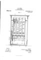
- FIG. 1 is a rear view of the device with the back of the casing moved
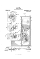
- Fig. 2 is a section through the device along the line 22 of Fig. 1
- Fig. 3 is a detail view from the inside of the device, showing a coin in its initial position after being deposited
- Fig. 3 is a similar view showing the engagement of the coin and the pin
- Fig. 3 is a similar view showing the coin passing through the opening to be deposited
- Fig. i is a detail view in section, showing the construction of the operating lever and the cam rollers.
- I provide a main casing consisting of a front 1 and provided with a transparent pane 2, a bottom 3, a top 4:, and a removable back 5.
- the bottom 3 is extended to provide an inclosed box 6, having a top 7 which forms a receiving Specification of Letters Patent.
- the base for the article to be vended.
- a covered chute 8 Disposed above the base 7 is a covered chute 8 provided with an opening 9 through which the article passes when it is released from the stack.
- the device is, preferably, provided with resilient feet 10.
- the exterior casing Within the exterior casing is a receptacle for the articles to be vended consisting of the side walls 11 and 12, a bottom 13, a false bottom 14 provided with slots 15, and a series of vertical partitions such as those shown at 16, 17 and 18.
- a cross member 19 holds these partitions at their rear ends, while at the front end they are held by means of the cross strip 20 (see Fig. 2).
- the walls 11 and 12, 13 and 14, as well as the partitions 16, 17 and 18, and the strips 19 and 20 are made, preferably, of metal.
- the partitions are flanged at their rear end, as shown at 16, 17 and 18, and at their front ends to provide rectangular chutes for the reception of articles to be vended.
- a shaft 21 Centrally disposed of the receptacle, between the false bottom 1 1 and the bottom 13, is a shaft 21, which is provided with arms 22, 23, 241 and 25 disposed at an angle of 90 degrees from each other, as shown in Fig. 2.
- the ends of these arms are curved and are adapted to extend through their respective slots 15 in the partition 14 and through registcring slots 26 in the curved bottom 26 of the chute 8.
- a wheel 27 Secured on a reduced end of the shaft 21, outside of the partition 11, which forms a bearing for the shaft, is a wheel 27, which is provided with an integral sleeve 28 bearing a set screw 29 by which the wheel may be adjustably secured.
- the wheel 27 bears the cam wheels 30, 31, 32 and 33, which are mounted to turn on screws such as that shown at 34- in Fig. 4:.
- a disk 35 Between the wall 27 and the side 11 is loosely mounted a disk 35, which is provided with a recess 35 (see Fig. 3) arranged to receive a coin, and has at one end of the recess an extension 35 for engaging the coin 36.
- the member 35 is of the general shape shown in Figs.
- a coin chute 40 is secured to the side of the member 11 and terminates in a slot 41 in the front member 1. The lower end of this chute terminates immediately above the re cess 35 of the plate 35-when the latter is in its normal position.
- a stop wheel 42 Arranged to cooperate with the cam wheels 30, 31, 32 and 33 is a stop wheel 42, which is pivotally mounted on the arm 43 of a lever. This lever is pivoted at 44, and the other arin 45 is held by means of a spring 46, which is fastened to the side 11.
- the back 5. may be removed by unlocking the device by inserting a key in the lock 47, and withdrawing the bolt 48 (see Fig. 2).
- the back may then be swung outwardly in the direction indicated by the arrow, and when the lock clears the top 4, it may be pulled upwardly so as to disengage the retaining cleats 49 at the bottom from the upturned flange 5 (see Fig. 2).
- the retainer may now be removed by swinging it in the direction indicated by the arrow, the handle 37 being withdrawn from a slot 50 in the front of the machine.
- the apparatus above described is simple with an extension, and a coin chute having its lower end terminating between a pin on said wheel and the extension on said lever, whereby a movement of said lever will cause the engagement of the pin through the medium of the coin thereby rotating the shaft, the rotation of said wheel and lever serving to bring the coin into registration with the coin delivery opening whereby the coin is projected through the wall of the receptacle.
- an exterior casing a receptacle disposed within said casing, the side walls of said receptacle being spaced therefrom, one of said side walls having a coin delivery opening, an operating cle, a wheel secured to said operating shaft 3 and provided with pins, an operating lever loosely mounted on said shaft and provided with an extension, said lever having a bentportio-n arranged to extend through said coin delivery opening, said bent portion serving to limit the movement of the lever in either direction, and a coin chute for depositing.
- a coin between the extension on said lever and one of said pins whereby the movement of the lever will cause the movement of the main wheel, the movement of the lever and main wheel serving to bring the coin into registration with the coin delivery opening and to cause the projection of the coin therethrough.
- a vending machine an exterior casing, a receptacle disposed therein having a coin delivery opening in one of its walls, an outwardly turned flange carried by said wall adjacent to said opening, an operating shaft sequently bringing. the coin into registration with said coin opening whereby the coin is projected through the opening, the flange on said opening serving to prevent the 00111 from falling outside of the receptacle.
Landscapes
- Physics & Mathematics (AREA)
- General Physics & Mathematics (AREA)
- Vending Machines For Individual Products (AREA)
Description
'G. F. GRESS. YBNDING- MACHINE. APPLICATION FILED MAY 10,1910.
Patented May 9, 1911.
2 SHEETS-SHEET 1. v
Haw
mun)
INVENTOR RES-5,
WITNESSES: /z.
ATTORNEYS c. P. cREss. VENDING MAOHINE.
AIPLIOATION FILED MAY 10,1}910.
Patented May 9, 1911.
2 BHEETB-SHEET 2.
m: mm W6 M 6 WITNESSES:
ATTOHNE Y8 UNITED sTAr s PATENT OFFICE.
CHARLES F. CRESS, OF FRANKFORT, INDIANA.
VENDING-MACHINE;
To all whom it may concern:
Be it known that I, CHARLES F. Gauss, a citizen of the United States, and a resident of Frankfort, in the county of Clinton and State of Indiana, have made certain new and useful Improvements in Vending-Machines, of which the following is a specification.
My invention relates to improvements in vending machines, and it consists in the. combinations, constructions and arrangements herein described and claimed.
An object of my invention is to provide a device in which the release of the article to be vended is accomplished by means of a coin, through mechanism which consists of comparatively few parts, and is, therefore, not liable to get out of order.
A further object of my invention is to provide a device in which there are a plurality of stacks of articles to be vended with means for feeding an article from the bottom of each stack successively, so that the height of all the stacks will be approximately the same.
A further object of my invention is to provide a device which may be located within an outer casing and which may be readily removed therefrom in order to inspect the working parts or for any other reason.
Other objects and advantages will appear in the following specification, and the novel features of the device will be particularly pointed out in the appended claims.
My invention is illustrated in the accompanying drawings, forming part of this application in which similar reference characters indicate like parts in the several views, and in which Figure 1 is a rear view of the device with the back of the casing moved, Fig. 2 is a section through the device along the line 22 of Fig. 1, Fig. 3 is a detail view from the inside of the device, showing a coin in its initial position after being deposited, Fig. 3 is a similar view showing the engagement of the coin and the pin, Fig. 3 is a similar view showing the coin passing through the opening to be deposited, and Fig. i is a detail view in section, showing the construction of the operating lever and the cam rollers.
In carrying out my invention, I provide a main casing consisting of a front 1 and provided with a transparent pane 2, a bottom 3, a top 4:, and a removable back 5. The bottom 3 is extended to provide an inclosed box 6, having a top 7 which forms a receiving Specification of Letters Patent.
Application filed May 10, 1910.
Patented May 9, 1911.
Serial No. 560,491.
base for the article to be vended. Disposed above the base 7 is a covered chute 8 provided with an opening 9 through which the article passes when it is released from the stack. The device is, preferably, provided with resilient feet 10.
The description thus far has had to do with the exterior casing. Within the exterior casing is a receptacle for the articles to be vended consisting of the side walls 11 and 12, a bottom 13, a false bottom 14 provided with slots 15, and a series of vertical partitions such as those shown at 16, 17 and 18. A cross member 19 holds these partitions at their rear ends, while at the front end they are held by means of the cross strip 20 (see Fig. 2). The walls 11 and 12, 13 and 14, as well as the partitions 16, 17 and 18, and the strips 19 and 20 are made, preferably, of metal. The partitions are flanged at their rear end, as shown at 16, 17 and 18, and at their front ends to provide rectangular chutes for the reception of articles to be vended.
Centrally disposed of the receptacle, between the false bottom 1 1 and the bottom 13, is a shaft 21, which is provided with arms 22, 23, 241 and 25 disposed at an angle of 90 degrees from each other, as shown in Fig. 2. The ends of these arms are curved and are adapted to extend through their respective slots 15 in the partition 14 and through registcring slots 26 in the curved bottom 26 of the chute 8.
Secured on a reduced end of the shaft 21, outside of the partition 11, which forms a bearing for the shaft, is a wheel 27, which is provided with an integral sleeve 28 bearing a set screw 29 by which the wheel may be adjustably secured. The wheel 27 bears the cam wheels 30, 31, 32 and 33, which are mounted to turn on screws such as that shown at 34- in Fig. 4:. Between the wall 27 and the side 11 is loosely mounted a disk 35, which is provided with a recess 35 (see Fig. 3) arranged to receive a coin, and has at one end of the recess an extension 35 for engaging the coin 36. The member 35 is of the general shape shown in Figs. 3, 3 and 3 and is provided with an integral lever 37, which is bent inwardly as shown at 37*, and then outwardly as shown at 37", terminating in a straight handle. On the inner side of the wall 27 are the four pins 27 The side wall 11 is provided with a coin delivery opening 38 whose forward edge is stamped to leave a deflecting plate 39. It will be seen that the bent portion 37 a of the lever 37 extends partly through this opening 38.
A coin chute 40 is secured to the side of the member 11 and terminates in a slot 41 in the front member 1. The lower end of this chute terminates immediately above the re cess 35 of the plate 35-when the latter is in its normal position.
Arranged to cooperate with the cam wheels 30, 31, 32 and 33 is a stop wheel 42, which is pivotally mounted on the arm 43 of a lever. This lever is pivoted at 44, and the other arin 45 is held by means of a spring 46, which is fastened to the side 11.
From the foregoing description the various parts of the device or operation thereof may be very readily understood. In charging the apparatus the back 5. may be removed by unlocking the device by inserting a key in the lock 47, and withdrawing the bolt 48 (see Fig. 2). The back may then be swung outwardly in the direction indicated by the arrow, and when the lock clears the top 4, it may be pulled upwardly so as to disengage the retaining cleats 49 at the bottom from the upturned flange 5 (see Fig. 2). The retainer may now be removed by swinging it in the direction indicated by the arrow, the handle 37 being withdrawn from a slot 50 in the front of the machine. Ordinarily it will not be necessary to remove the retainer for the packages may be inserted above the cross member 19, and may be stacked up in their respective chutes. l/Vhen the device is filled the cover is re placed and the machine is ready for opera tion. A customer inserts a coin in the slot 41, which falls down into the position shown in Fig. 3; he then presses the lever 37 in the direction indicated by the arrow. The projection 35 will engage the coin on one side and force it against the pin 27*, thereby turning the wheel 27, and, hence, the rod 21. As the wheel is turned the cam wheels 30, 31, 32 or 33 as the case may be will engage the roller 42 and force the latter outwardly against the tension of the spring 46. As soon as the center of the cam wheel has passed the center of the roller the latter springs back into position, thereby giving the shaft a quick turn. One of the arms 22, 23, 24 or 25 will engage the bottom of the article, and cause it to be projected forwardly into the chute 8, when it falls down upon the base 7. As soon as the handle 37 is released it returns to its position under the influence of the spring 51. The coin in the meantime has fallen through the opening 38 into the bottom of the receptacle. The movement of the lever 37 is limited by the engagement of the bent portion 37 a with the upper and lower edges of the opening 38. The projection 39 prevents the coin from being deposited outside of the receptacle. WVhen another coin is deposited and the lever again worked another arm will come into play and will cause the bottom box, or article, in another stack to be projected forwardly. If the handle 37 should be worked without depositing the coin the bent portion 37 of the lever will pass over one of the pins 27 (see Fig. 3) while the projection 35 will pass under the pin 27 near the upper end of the pin 38. It is apparent that the lever will simply turn idly on the shaft and will not cause the arms to revolve.
The apparatus above described is simple with an extension, and a coin chute having its lower end terminating between a pin on said wheel and the extension on said lever, whereby a movement of said lever will cause the engagement of the pin through the medium of the coin thereby rotating the shaft, the rotation of said wheel and lever serving to bring the coin into registration with the coin delivery opening whereby the coin is projected through the wall of the receptacle.
2. In a vending machine, an exterior casing, a receptacle disposed within said casing, the side walls of said receptacle being spaced therefrom, one of said side walls having a coin delivery opening, an operating cle, a wheel secured to said operating shaft 3 and provided with pins, an operating lever loosely mounted on said shaft and provided with an extension, said lever having a bentportio-n arranged to extend through said coin delivery opening, said bent portion serving to limit the movement of the lever in either direction, and a coin chute for depositing. a coin between the extension on said lever and one of said pins, whereby the movement of the lever will cause the movement of the main wheel, the movement of the lever and main wheel serving to bring the coin into registration with the coin delivery opening and to cause the projection of the coin therethrough.
3. In a vending machine, an exterior casing, a receptacle disposed therein having a coin delivery opening in one of its walls, an outwardly turned flange carried by said wall adjacent to said opening, an operating shaft sequently bringing. the coin into registration with said coin opening whereby the coin is projected through the opening, the flange on said opening serving to prevent the 00111 from falling outside of the receptacle.
CHARLES F. GRESS.
Witnesses:
GEORGE M. SPAHR, SAMUEL A. Monmson.
Copies of this patent may be obtained for five cents each, by addressing the Commissioner of latents, Washington, D. G.
Priority Applications (1)
| Application Number | Priority Date | Filing Date | Title |
|---|---|---|---|
| US56049110A US992113A (en) | 1910-05-10 | 1910-05-10 | Vending-machine. |
Applications Claiming Priority (1)
| Application Number | Priority Date | Filing Date | Title |
|---|---|---|---|
| US56049110A US992113A (en) | 1910-05-10 | 1910-05-10 | Vending-machine. |
Publications (1)
| Publication Number | Publication Date |
|---|---|
| US992113A true US992113A (en) | 1911-05-09 |
Family
ID=3060448
Family Applications (1)
| Application Number | Title | Priority Date | Filing Date |
|---|---|---|---|
| US56049110A Expired - Lifetime US992113A (en) | 1910-05-10 | 1910-05-10 | Vending-machine. |
Country Status (1)
| Country | Link |
|---|---|
| US (1) | US992113A (en) |
Cited By (1)
| Publication number | Priority date | Publication date | Assignee | Title |
|---|---|---|---|---|
| US2542067A (en) * | 1946-09-10 | 1951-02-20 | Cleveland Detroit Corp | Cup dispensing machine |
-
1910
- 1910-05-10 US US56049110A patent/US992113A/en not_active Expired - Lifetime
Cited By (1)
| Publication number | Priority date | Publication date | Assignee | Title |
|---|---|---|---|---|
| US2542067A (en) * | 1946-09-10 | 1951-02-20 | Cleveland Detroit Corp | Cup dispensing machine |
Similar Documents
| Publication | Publication Date | Title |
|---|---|---|
| US1355583A (en) | Vending-machine | |
| US992113A (en) | Vending-machine. | |
| US772226A (en) | Vending-machine. | |
| US396674A (en) | Automatic selling-machine | |
| US640112A (en) | Prepayment or coin-in-the-slot machine. | |
| US593132A (en) | Charles spiro | |
| US444502A (en) | Newspaper-vending apparatus | |
| US1140220A (en) | Vending-machine. | |
| US1045514A (en) | Vending-machine. | |
| US1240413A (en) | Vending device. | |
| US1219861A (en) | Coin-controlled vending-machine. | |
| US579330A (en) | Coin-controlled yen ding-machine | |
| US541298A (en) | Thirds to william b | |
| US1025235A (en) | Vending-machine. | |
| US871824A (en) | Coin-operated vending-machine. | |
| US1236163A (en) | Vending-machine. | |
| US716506A (en) | Vending-machine. | |
| US1024748A (en) | Coin-controlled apparatus. | |
| US716507A (en) | Vending-machine. | |
| US545436A (en) | abelson | |
| US726934A (en) | Vending-machine. | |
| US699252A (en) | Coin-controlled newspaper-vending machine. | |
| US520769A (en) | cochran | |
| US492756A (en) | Coin-controlled vending-machine | |
| US1267662A (en) | Coin-control mechanism for vending-machines. |