US7802468B2 - Pressure sensor for vehicle and brake fluid pressure control apparatus for vehicle - Google Patents
Pressure sensor for vehicle and brake fluid pressure control apparatus for vehicle Download PDFInfo
- Publication number
- US7802468B2 US7802468B2 US12/228,160 US22816008A US7802468B2 US 7802468 B2 US7802468 B2 US 7802468B2 US 22816008 A US22816008 A US 22816008A US 7802468 B2 US7802468 B2 US 7802468B2
- Authority
- US
- United States
- Prior art keywords
- sleeve
- sensing element
- rod
- pressure sensor
- contact probe
- Prior art date
- Legal status (The legal status is an assumption and is not a legal conclusion. Google has not performed a legal analysis and makes no representation as to the accuracy of the status listed.)
- Expired - Fee Related, expires
Links
- 239000012530 fluid Substances 0.000 title claims abstract description 54
- 239000000523 sample Substances 0.000 claims abstract description 123
- 238000003825 pressing Methods 0.000 claims abstract description 9
- 238000003780 insertion Methods 0.000 claims description 45
- 230000037431 insertion Effects 0.000 claims description 45
- 239000000758 substrate Substances 0.000 description 22
- 238000004519 manufacturing process Methods 0.000 description 7
- 238000005476 soldering Methods 0.000 description 7
- 238000011109 contamination Methods 0.000 description 4
- 230000007774 longterm Effects 0.000 description 4
- 239000007769 metal material Substances 0.000 description 4
- 229920001707 polybutylene terephthalate Polymers 0.000 description 4
- 230000008901 benefit Effects 0.000 description 3
- 238000000034 method Methods 0.000 description 3
- 238000005192 partition Methods 0.000 description 3
- 238000009434 installation Methods 0.000 description 2
- -1 polybutylene terephthalate Polymers 0.000 description 2
- 239000004065 semiconductor Substances 0.000 description 2
- 229920003002 synthetic resin Polymers 0.000 description 2
- 239000000057 synthetic resin Substances 0.000 description 2
- 229920001169 thermoplastic Polymers 0.000 description 2
- 239000004416 thermosoftening plastic Substances 0.000 description 2
- 239000000428 dust Substances 0.000 description 1
- 230000005611 electricity Effects 0.000 description 1
- 239000000463 material Substances 0.000 description 1
- 238000012986 modification Methods 0.000 description 1
- 230000004048 modification Effects 0.000 description 1
- 229920005989 resin Polymers 0.000 description 1
- 239000011347 resin Substances 0.000 description 1
- 238000003466 welding Methods 0.000 description 1
Images


Classifications
-
- B—PERFORMING OPERATIONS; TRANSPORTING
- B60—VEHICLES IN GENERAL
- B60T—VEHICLE BRAKE CONTROL SYSTEMS OR PARTS THEREOF; BRAKE CONTROL SYSTEMS OR PARTS THEREOF, IN GENERAL; ARRANGEMENT OF BRAKING ELEMENTS ON VEHICLES IN GENERAL; PORTABLE DEVICES FOR PREVENTING UNWANTED MOVEMENT OF VEHICLES; VEHICLE MODIFICATIONS TO FACILITATE COOLING OF BRAKES
- B60T8/00—Arrangements for adjusting wheel-braking force to meet varying vehicular or ground-surface conditions, e.g. limiting or varying distribution of braking force
- B60T8/32—Arrangements for adjusting wheel-braking force to meet varying vehicular or ground-surface conditions, e.g. limiting or varying distribution of braking force responsive to a speed condition, e.g. acceleration or deceleration
- B60T8/34—Arrangements for adjusting wheel-braking force to meet varying vehicular or ground-surface conditions, e.g. limiting or varying distribution of braking force responsive to a speed condition, e.g. acceleration or deceleration having a fluid pressure regulator responsive to a speed condition
- B60T8/36—Arrangements for adjusting wheel-braking force to meet varying vehicular or ground-surface conditions, e.g. limiting or varying distribution of braking force responsive to a speed condition, e.g. acceleration or deceleration having a fluid pressure regulator responsive to a speed condition including a pilot valve responding to an electromagnetic force
- B60T8/3615—Electromagnetic valves specially adapted for anti-lock brake and traction control systems
- B60T8/3675—Electromagnetic valves specially adapted for anti-lock brake and traction control systems integrated in modulator units
- B60T8/368—Electromagnetic valves specially adapted for anti-lock brake and traction control systems integrated in modulator units combined with other mechanical components, e.g. pump units, master cylinders
-
- F—MECHANICAL ENGINEERING; LIGHTING; HEATING; WEAPONS; BLASTING
- F15—FLUID-PRESSURE ACTUATORS; HYDRAULICS OR PNEUMATICS IN GENERAL
- F15B—SYSTEMS ACTING BY MEANS OF FLUIDS IN GENERAL; FLUID-PRESSURE ACTUATORS, e.g. SERVOMOTORS; DETAILS OF FLUID-PRESSURE SYSTEMS, NOT OTHERWISE PROVIDED FOR
- F15B13/00—Details of servomotor systems ; Valves for servomotor systems
- F15B13/02—Fluid distribution or supply devices characterised by their adaptation to the control of servomotors
- F15B13/06—Fluid distribution or supply devices characterised by their adaptation to the control of servomotors for use with two or more servomotors
- F15B13/08—Assemblies of units, each for the control of a single servomotor only
- F15B13/0803—Modular units
- F15B13/0846—Electrical details
- F15B13/086—Sensing means, e.g. pressure sensors
Definitions
- the present invention is related to a pressure sensor for a vehicle and a brake fluid pressure control apparatus for a vehicle equipped with the pressure sensor.
- an electronic control unit controls various parts provided in fluid passages based on the pressure of brake fluid measured by a pressure sensor.
- a conventional pressure sensor includes a sensing element 10 for measuring the pressure of brake fluid in fluid passages, a sensor housing 20 for accommodating the sensing element 10 and a contact probe 630 that is electrically connected to the sensing element 10 at one end thereof and is electrically connected to the electronic control unit 300 at the other end thereof (disclosed in unexamined Japanese patent application publication No. 2002-542107, paragraphs 0015 and 0016, and FIG. 1).
- the conventional contact probe 630 includes a sleeve 631 , a coil spring 632 housed in the sleeve 631 , a rod 633 inserted into the sleeve 631 .
- the sleeve 631 and the rod 633 are pressed by the pressing force of the coil spring 632 in the direction of their elongation.
- the contact probe 630 is slidably inserted into an insertion hole 22 c formed at a top end part of the sensor housing 20 .
- the sleeve 631 and the rod 633 are elongated by the pressing force of the coil spring 632 so that the rod 633 is pressed to a connection part 11 a of the sensing element 10 and the sleeve 631 is pressed to a connection part 302 of the electronic control unit 300 .
- the sleeve 631 is pressed to the connection part 302 of the electronic control unit 300 , whereby the contact probe 630 and the electronic control unit 300 are electrically connected.
- the contact probe 630 is not fixed to the electronic control unit 300 , the pressure sensor and the electronic control unit 300 can be easily connected or disconnected.
- the rod 633 is pressed to the connection part 11 a of the sensing element 10 and the sleeve 631 is pressed to the connection part 302 of the electronic control unit 300 .
- the electrical connections at both ends of the contact probe 630 are contact connection, which causes a problem that the contact resistance is increased.
- the present invention is made in view of the above problems and an object thereof is to provide a pressure sensor for a vehicle that enables to improve the reliability of the connection of a contact probe and a sensing element, to prevent the electrical contact resistance of the contact probe from being increased, to easily position the contact probe in a sensor housing when assembling the contact probe in the sensor housing and improve workability of assembling the contact probe into the sensor housing, and a brake fluid pressure control apparatus for a vehicle equipped with the pressure sensor.
- First aspect of the present invention provides a pressure sensor for a vehicle including a sensing element for measuring a pressure of fluid in a fluid passage, a sensor housing for accommodating the sensing element, and a contact probe that is electrically connected to the sensing element at one end thereof and is electrically connected to a control unit that is disposed outside of the sensor housing at the other end thereof, the contact probe including a sleeve, an elastic member that is housed in the sleeve, and a rod that is inserted in the sleeve, wherein either one of the rod and the sleeve contacts with a connection part of the sensing element in a state that the either one of the rod and the sleeve is fixed in the sensor housing, and the other one of the rod and the sleeve is pressed to a connection part of the control unit by pressing force of the elastic member.
- the sleeve or the rod connected to the sensing element is stably fixed to the sensor housing, it is possible to prevent contamination from being generated between the contact probe and the sensing element that may be caused by influence of the environment around the pressure sensor or the slide of the contact probe, which allows to improve the reliability of the connection in the long term.
- the electrical contact resistance between the contact probe and the sensing element can be prevented from being increased.
- the sleeve or the rod connected to the sensing element is stably fixed to the sensor housing, the position of the contact probe can be easily determined when assembling the contact probe into the sensor housing.
- workability of assembling the contact probe into the sensor housing can be improved, which achieves low production cost of the pressure sensor.
- the sleeve may be connected to the sensing element and the rod may be connected to the control unit, and the sleeve may be press-fit into an insertion hole formed in the sensor housing.
- the sleeve is press-fit into the insertion hole of the sensor housing, which allows to fix the contact probe in the sensor housing easily.
- the sleeve may be a closed-end cylinder and may include a diameter shrunk portion formed at an opening edge of the sleeve to prevent the rod from slipping off, and the sensor housing may include a wall portion that surrounds the diameter shrunk portion.
- the rod may be connected to the sensing element and the sleeve may be connected to the control unit, and the rod may be press-fit into an insertion hole formed in the sensor housing and the sleeve may be slidably inserted into the insertion hole.
- the rod is press-fit into the insertion hole of the sensor housing, which allows to fix the contact probe in the sensor housing easily.
- the sleeve and the sensing element may be connected in a state that the sleeve and the sensing element are fixed.
- the rod and the sensing element may be connected in a state that the rod and the sensing element are fixed.
- the sleeve or the rod is fixed to the sensing element by soldering, for example, and thus the contact probe and the sensing element are inseparably connected, which further improves the reliability of the connection between the contact probe 30 and the sensing element 10 .
- a plurality of the contact probes may be provided at a top end surface of the sensor housing, and at least one of the contact probes may be disposed in such a manner that a distance from the at least one contact probe to a center point of the top end surface differs from distances from the other contact probes to the center point of the top end surface.
- the direction of the pressure sensor for the vehicle can be judged based on the positions of the contact probes.
- the direction of the pressure sensor can be easily determined, which allows to improve the workability of installing the pressure sensor.
- a second aspect of the present invention provides a brake fluid pressure control apparatus for a vehicle equipped with the aforementioned pressure sensor for the vehicle, including the fluid passage for connecting a master cylinder to wheel brakes; and a control unit for controlling the pressure of the fluid applied to the wheel brakes based on the pressure of the fluid measured by the sensing element of the pressure sensor for the vehicle.
- the brake fluid pressure control apparatus for the vehicle is equipped with the pressure sensor of the present invention, the reliability of the connection between the contact probe and the sensing element can be improved, and the electrical contact resistance between the contact probe and the sensing element can be also prevented from being increased, which improves the reliability of the control of the brake fluid pressure control apparatus for the vehicle.
- the cost incurred for the pressure sensor for the vehicle can be also reduced, which achieves low production cost of the brake fluid pressure control apparatus for the vehicle.
- the reliability of the connection between the contact probe and the sensing element can be improved. Furthermore, the electrical contact resistance between the contact probe and the sensing element can be also prevented from being increased, which improves the reliability of the control of the brake fluid pressure control apparatus for the vehicle. The cost incurred for the pressure sensor for the vehicle can be also reduced, which achieves low production cost of the brake fluid pressure control apparatus for the vehicle.
- FIG. 1 is an exploded perspective view of a brake fluid pressure control apparatus for a vehicle equipped with a pressure sensor according to an embodiment.
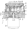
- FIG. 2 is a sectional slide view of the brake fluid pressure control apparatus for a vehicle equipped with the pressure sensor according to the embodiment.
- FIG. 3A is a perspective view of the pressure sensor according to the embodiment.
- FIG. 3B is a view of the pressure sensor according to the embodiment seen from the side of contact probes.
- FIG. 4 is an enlarged sectional view of a part of the pressure sensor according to the embodiment.
- FIG. 5 is a sectional slide view of a contact probe provided for the pressure sensor according to the embodiment.
- FIG. 6 is an enlarged sectional view of a part of a pressure sensor according to another embodiment.
- FIG. 7 is a sectional slide view of a contact probe provided for the pressure sensor according to the another embodiment.
- FIG. 8 is a view of the pressure sensor according to the another embodiment seen from the side of the contact probes.
- FIG. 9 is an enlarged sectional view of a part of a conventional pressure sensor.
- the configuration of a brake fluid control apparatus for a vehicle U is described below with reference to FIG. 1 .
- the brake fluid control apparatus for a vehicle U includes a base 100 on which electrical parts, such as electromagnetic valves V and a pressure sensor 1 , and a reciprocating pump P are mounted, a motor 200 which is the power source of the reciprocating pump P, an electronic control unit 300 that controls opening and closing of the electromagnetic valves V and the operation of the motor 200 , a housing 400 that accommodates the electrical parts protruding from the base 100 and the electronic control unit 300 , and a cover 500 that covers the opening of the housing 400 .
- the electronic control unit 300 may also be referred to as a control unit.
- the base 100 is made of metallic material formed in substantially rectangular parallelepiped shape and includes fluid passages (oil passages) for brake fluid inside thereof. Formed on a front surface 101 of the base 100 are closed-end mounting holes 151 into which electrical parts such as the electromagnetic valves V and the pressure sensor 1 are mounted. An upper surface 103 of the base 100 is provided with four exit ports to which pipes to wheel brakes (not shown) are connected. The bottom surface of the base 100 includes reserver holes (not shown) into which reserver components R constituting a reserver are mounted. The side surface 105 of the base 100 is provided with a pump hole 155 into which the reciprocating pump P is mounted. The holes formed on the base 100 are communicated with one another directly or via the passages (not shown) formed inside of the base 100 .
- the motor 200 is a power source of the reciprocating pump P and is integrally fixed to a back surface 102 of the base 100 as shown in FIG. 1 .
- An endless seal member 214 is interposed between the motor 200 and the back surface 102 of the base 100 to fluid-tightly seal between the motor 200 and the back surface 102 .
- An output axis 210 of the motor 200 is provided with an eccentric shaft 211 , and the ball bearings 212 are fit into the eccentric shaft 211 .
- the eccentric shaft 211 and the ball bearings 212 are inserted into a motor mounting hole 154 .
- the motor 200 includes a motor bus bar 220 for providing electricity to a rotor (not shown) above the output axis 210 .
- the motor bus bar 220 is inserted through a terminal hole 140 and is connected to a terminal 8 b of the housing 400 .
- the electronic control unit 300 is made by mounting semiconductor chips on a substrate 301 on which electronic circuits (conductive member) are printed, and is configured to control opening and closing of the electromagnetic valves V and the operation of the motor 200 based on information obtained through various types of sensors such as the pressure sensor 1 , wheel speed sensors (not shown) and programs that are stored in advance.
- the conductive member 303 is provided in a partition 401 that is formed closer to the base 100 than the substrate 301 in the housing 400 and extends along the partition 401 . As shown in FIG. 4 , the conductive member 303 includes a connection part 302 that is exposed to the side of the partition 401 that is opposed to the base 100 . When the contact probe 30 of the pressure sensor 1 comes in contact with the connection part 302 , the pressure sensor 1 and the electronic control unit 300 are electrically connected.
- the housing 400 shown in FIG. 1 covers the electrical parts, such as the electromagnetic valves V and the pressure sensor 1 , which protrude from the front surface 101 of the base 100 , and is integrally fixed to the front surface 101 of the base 100 .
- the housing 400 also includes a first space K 1 and a second space K 2 as shown in FIG. 2 .
- the first space K 1 receives the electrical parts such as the electromagnetic valves V, electromagnetic coils V 1 and the pressure sensor 1 .
- the second space K 2 accommodates the electronic control unit 300 .
- the housing 400 is formed of a thermoplastic synthetic resin such as polybutylene terephthalate (PBT).
- the cover 500 of the housing 400 covers and seals the opening of the front surface (the surface on the side of the second space K 2 ) of the housing 400 and is fixed to the front surface edges of the housing 400 by welding, adhesion or the like.
- the cover 500 is also formed of a thermoplastic synthetic resin such as polybutylene terephthalate (PBT).
- the pressure sensor 1 shown in FIG. 2 is an electrical unit for measuring the pressure of the brake fluid in the fluid passages formed in the base 100 .
- the pressure sensor 1 is mounted on the front surface 101 of the base 100 by inserting its base end (the end on the side of the base 100 ) into the mounting hole 151 formed on the front surface 101 of the base 100 .
- the pressure sensor 1 includes a sensing element 10 (refer to FIG. 4 ) for measuring the pressure of the brake fluid in the fluid passages, the sensor housing 20 for accommodating the sensing element 10 and the contact probe 30 that is electrically connected to the sensing element 10 at one end thereof and is electrically connected to the electronic control unit 300 at the other end thereof (refer to FIG. 2 ).
- the sensor housing 20 includes a housing part 21 made of a metallic material formed in closed-end cylinder shape and a supporting member 22 made of resin material that is circular form in cross-section and is inserted into the housing part 21 through a top end opening 21 a of the housing part 21 .
- the supporting member 22 includes a large diameter portion 22 a inserted in the housing part 21 and a small diameter portion 22 b that protrudes outside through the top end opening 21 a of the housing part 21 as shown in FIG. 4 .
- a ring 21 b is fit into the part of the small diameter portion 22 b that is disposed in the housing part 21 to prevent from generating a gap between the small diameter portion 22 b and the housing part 21 , which may be generated from the dimension error of the small diameter portion 22 b and the housing part 21 .
- a cut-out 22 i is formed on a part of the outer circumferential surface of the small diameter portion 22 b .
- the position of the pressure sensor 1 can be easily determined by holding the cut-out 22 i of the supporting member 22 of the pressure sensor 1 in FIG. 3A by a jig (not shown), whereby the connection part 302 of the conductive member 303 connected to the electronic circuit of the substrate 301 in FIG. 2 and the contact probe 30 of the pressure sensor 1 can be made into contact with each other with high reliability.
- the supporting member 22 includes four insertion holes 22 c , each of which penetrates through the supporting member 22 in the axial direction thereof (refer FIG. 4 ) as shown in FIG. 3B .
- Each insertion hole 22 c is formed on the circumference of a circle of which center is a center point A of the top end surface 22 d of the supporting member 22 at every 90-degree angular interval. In other words, the distance between each insertion hole 22 c and the center of the top end surface 22 d of the supporting member 22 (i.e. radius) is the same.
- Each insertion hole 22 c includes a front portion 22 f , a middle portion 22 g and a back portion 22 h in order from the top end surface 22 d of the supporting member 22 toward a base end surface 22 e as shown in FIG. 4 .
- a sleeve 31 of the contact probe 30 which is described later, is press-fit into the middle portion 22 g and the back portion 22 h , and thus the diameter of the back portion 22 h is made smaller than that of the middle portion 22 g to correspond to the outer diameter of a protruding portion 31 a of the sleeve 31 .
- the diameter of the front portion 22 f is made larger than that of the middle portion 22 g to generate space between the inner circumferential surface of the front portion 22 f and the outer circumferential surface of the sleeve 31 when the contact probe 30 is inserted into the insertion hole 22 c.
- the sensing element 10 is accommodated in the housing part 21 and measures the pressure of the brake fluid in the fluid passages.
- the sensing element 10 further converts the measured pressure value into an electric signal and outputs the electric signal.
- the configuration of the sensing element 10 employs the configuration that has been widely known, and thus the detailed description thereof will be omitted.
- the sensing element 10 of the embodiment includes a substrate 11 disposed on a position opposed to the base end surface 22 e of the supporting member 22 .
- An electronic circuit (conductive member) is printed on the substrate 11 , and semiconductor chips are also mounted on the substrate 11 .
- connection holes 11 a are formed in the substrate 11 .
- Each connection hole 11 a is conducted to an electronic circuit.
- the connection hole 11 a is an electrical connection portion that electrically connects the contact probe 30 with the electronic circuit when the protruding portion 31 a of the contact probe 30 is inserted through the connection hole 11 a and is made into contact with the connection hole 11 a .
- the protruding portion 31 a of the contact probe 30 and the connection hole 11 a of the substrate 11 are fixed by soldering on a base end surface of the substrate 11 .
- the contact probe 30 includes the sleeve 31 that is made of metallic material formed in closed-end cylinder shape, a coil spring 32 that is an elastic member housed in the sleeve 31 and a rod 33 that is made of metallic material and is inserted into the sleeve 31 as shown in FIG. 5 .
- An opening is formed on the front end (the end on the side of the electronic control unit 300 ) of the sleeve 31 , and the rod 33 is inserted into the opening.
- a diameter shrunk portion 31 c for preventing the rod 33 from slipping off is formed at the opening edge 31 b of the sleeve 31 .
- the diameter shrunk portion 31 c is formed by calking the opening edge 31 b after the rod 33 is inserted into the sleeve 31 .
- a stopper flange 31 d is formed around the outer circumferential surface of the sleeve 31 in a protruding condition.
- the distance between the stopper flange 31 d and the opening edge 31 b of the sleeve 31 is designed to be the same as the depth of the front portion 22 f of the insertion hole 22 c of the supporting member 22 .
- the opening edge of the insertion hole 22 c is arranged around the opening edge 31 b of the sleeve 31 .
- the inner circumferential surface of the front portion 22 f of the insertion hole 22 c is a wall that surrounds the diameter shrunk portion 31 c in the embodiment.
- a rod-shaped protruding portion 31 a protruding backward (toward the side of the sensing element 10 ) is formed on the bottom portion 31 f of the sleeve 31 .
- the diameter of the protruding portion 31 a of the sleeve 31 is designed smaller than that of the bottom portion 31 f of the sleeve 31 .
- the coil spring 32 is housed in the sleeve 31 in a compressed state.
- the front end of the coil spring 32 is in contact with a rear surface 33 a of the rod 33 , and the rear end thereof is in contact with a bottom surface 31 e of the sleeve 31 .
- the rod 33 is pressed by pressing force of the coil spring 32 in the direction in which the rod 33 protrudes from the sleeve 31 (the direction toward the right side of FIG. 5 ).
- the rod 33 includes a large diameter potion 33 b that is slidably inserted into the sleeve 31 and a small diameter portion 33 c that protrudes outside from the opening of the sleeve 31 .
- the step between the large diameter portion 33 b and the small diameter portion 33 c is engaged with the diameter shrunk portion 31 c of the sleeve 31 so that the rod 33 is prevented from slipping off from the sleeve 31 .
- the sleeve 31 is press-fit into the middle portion 22 g and the back portion 22 h of the insertion holes 22 c , whereby the contact probe 30 is fixed in the insertion holes 22 c .
- the protruding portion 31 a of the sleeve 31 protrudes from the base end surface 22 e of the supporting member 22 and is further inserted through the connection hole 11 a of the substrate 11 of the sensing element 10 .
- the protruding portion 31 a and the connection hole 11 a are fixed by soldering.
- the contact probe 30 and the sensing element 10 are electrically connected.
- the contact probe 30 is inserted into the insertion hole 22 c from the top end surface 22 d of the supporting member 22 as shown in FIG. 4 .
- the stopper flange 31 d of the contact probe 30 is abutted to the step between the front portion 22 f and the middle portion 22 g of the insertion hole 22 c, the position of the contact probe 30 is fixed in the insertion hole 22 c .
- the sleeve 31 of the contact probe 30 is press-fit into the insertion hole 22 c , and thus the contact probe 30 is fixed in the sensor housing 20 .
- the contact probe 30 When the contact probe 30 is inserted into the insertion hole 22 c of the supporting member 22 , the protruding portion 31 a of the sleeve 31 is inserted through the connection hole 11 a of the substrate 11 of the sensing element 10 , whereby the contact probe 30 and the sensing element 10 are electrically connected.
- the protruding portion 31 a of the contact probe 30 and the connection hole 11 a of the substrate 11 are fixed by soldering from the side of the housing part 21 .
- the sleeve 31 connected to the sensing element 10 is stably fixed to the sensor housing 20 as shown in FIG. 4 , it is possible to prevent contamination from being generated between the contact probe 30 and the sensing element 10 that may be caused by influence of the environment around the pressure sensor 1 or the slide of the contact probe 30 , which allows to improve the reliability of the connection in the long term.
- the sleeve 31 is stably connected to the sensing element 10 , the electrical contact resistance between the contact probe 30 and the sensing element 10 can be prevented from being increased.
- the sleeve 31 connected to the sensing element 10 is stably fixed to the supporting member 22 of the sensor housing 20 , the position of the contact probe 30 can be easily determined when fixing the contact probe 30 to the sensor housing 20 .
- workability of fixing the contact probe 30 to the sensor housing 20 can be improved, which achieves low production cost of the pressure sensor 1 .
- the reliability of the connection between the contact probe 30 and the sensing element 10 can be improved.
- the electrical contact resistance between the contact probe 30 and the sensing element 10 can be also prevented from being increased, which improves the reliability of the control of the brake fluid pressure control apparatus for a vehicle U.
- the cost incurred for the pressure sensor 1 can be also reduced, which achieves low production cost of the brake fluid pressure control apparatus for a vehicle U.
- the sleeve 31 is fixed to the connection hole 11 a of the substrate 11 of the sensing element 10 by soldering, and thus the contact probe 30 and the sensing element 10 are inseparably connected, which further improves the reliability of the connection between the contact probe 30 and the sensing element 10 .
- the sleeve 31 is press-fit into the insertion hole 22 c of the supporting member 22 , which allows to fix the contact probe 30 in the sensor housing 20 easily.
- the wall (the inner circumferential surface of the front portion 22 f of the insertion hole 22 c ) surrounding the diameter shrunk portion 31 c of the sleeve 31 is formed, and thus an external member hardly comes into contact with the diameter shrunk portion 31 c of the sleeve 31 when handling the pressure sensor 1 , whereby the contact probe 30 can be prevented from being damaged, which results in easy handling of the pressure sensor 1
- the contact probe 30 of the sleeve 31 is connected to the sensing element 10 and the rod 33 is connected to the electronic control unit 300 in the embodiment as shown in FIG. 4 , however, the pressure sensor may be configured in such a manner that a rod 43 is connected to the sensing element 10 and the sleeve 41 is connected to the electronic control unit 300 as shown in FIG. 6 for example.
- the rod 43 described in the another embodiment above includes a press-in portion 43 a that is press-fit into the insertion holes 22 c and a shaft part 43 b extending toward the sleeve 41 from the press-in portion 43 a .
- the diameter of the top end of the shaft part 43 b (the end on the side of the sleeve 41 ) is made larger, and the top end of the shaft part 43 b is slidable in the sleeve 41 .
- the sleeve 41 is slidably inserted into the insertion hole 22 c .
- a coil spring 42 is housed in the sleeve 41 in a compressed state as shown in FIG. 7 .
- An end of the coil spring 42 is locked to a protrusion 41 a formed along the inner circumferential surface of the sleeve 41 and the other end thereof is in contact with the front end surface of the rod 43 .
- a diameter shrunk portion 41 c is formed at the opening edge 41 b of the sleeve 41 .
- the diameter shrunk portion 41 c is formed by calking an opening circumferential edge 41 b after the rod 43 is inserted into the sleeve 41 .
- the front end of the shaft part 43 b of the rod 43 is engaged with the diameter shrunk portion 41 c of the sleeve 41 so that the rod 43 is prevented from slipping off from the sleeve 41 .
- the position of the contact probe 40 is determined in the insertion holes 22 c.
- the rod 43 is also inserted through the connection hole 11 a of the substrate 11 of the sensing element 10 , whereby the contact probe 40 and the sensing element 10 are electrically connected.
- the sleeve 41 is pressed toward the connection part 302 of the electronic control unit 300 by pressing force of the coil spring 42 , whereby the contact probe 40 and the electronic control unit 300 are electrically connected.
- the rod 43 connected to the sensing element 10 is stably fixed to the supporting member 22 of the sensor housing 20 , which allows to easily determine the position of the contact probe 40 when assembling the contact probe 40 in the sensor housing 20 .
- workability of assembling the contact probe 40 in the sensor housing 20 can be improved, which achieves low production cost of the pressure sensor.
- the four insertion holes 22 c formed on the supporting member 22 are disposed on the circumference of the circle of which center is the center point A of the top end surface 22 d of the supporting member 22 at every 90-degree angular interval as shown in FIG. 3B , however, the insertion holes 22 c may be disposed in such a manner that the distance between each insertion hole 22 c and the center point A of the top end surface 22 d of the supporting member 22 (i.e. radius) is not the same as shown in FIG. 8 .
- two insertion holes 22 c opposed to each other relative to the center point A and the other two insertion holes 22 c opposed to each other relative to the center point A are respectively disposed on the circumferences of two circles of which diameters are different.
- the four insertion holes 22 c are disposed at positions of which distances to the center point A of the top end surface 22 d of the supporting member 22 are different.
- the direction of the pressure sensor 1 can be judged based on the positions of the contact probes 30 .
- the direction of the pressure sensor 1 can be easily determined, which allows to improve the workability of installing the pressure sensor 1 .
- the protruding portion 31 a of the contact probe 30 and the connection hole 11 a of the substrate 11 of the sensing element 10 are fixed by soldering as shown in FIG. 4 , however, the protruding portion 31 a of the contact probe 30 and the connection hole 11 a of the substrate 11 of the sensing element 10 may be fixed by means other than soldering as long as the sensing element 10 and the contact probe 30 are securely connected.
- the contact probe 30 and the sensing element 10 may be electrically connected in a press-fit method in which a press-fit portion of which diameter is made larger than that of the connection hole 11 a of the substrate 11 of the sensing element 10 is formed at the protruding portion 31 a of the contact probe 30 and the press-fit portion is press-fit into the connection hole 11 a of the substrate 11 of the sensing element 10 .
- a press-fit portion whose diameter is smaller than that of the protruding portion 31 a may be formed at the connection hole 11 a of the substrate 11 of the sensing element 10 , and the protruding portion 31 a of the contact probe 30 may be press-fit into the connection hole 11 a of the substrate 11 .
Abstract
Description
-
- 1. In accordance with the pressure sensor for the vehicle of the present invention, it is possible to prevent contamination from being generated between the contact probe and the sensing element that may be caused by influence of the environment around the pressure sensor or the slide of the contact probe, which allows to improve the reliability of the connection in the long term. Furthermore, the electrical contact resistance between the contact probe and the sensing element can be prevented from being increased. Moreover, the position of the contact probe can be easily determined when assembling the contact probe into the sensor housing. Thus, workability of assembling the contact probe into the sensor housing can be improved, which achieves low production cost of the pressure sensor.
Claims (9)
Applications Claiming Priority (2)
| Application Number | Priority Date | Filing Date | Title |
|---|---|---|---|
| JP2007-209160 | 2007-08-10 | ||
| JP2007209160A JP4568309B2 (en) | 2007-08-10 | 2007-08-10 | In-vehicle pressure sensor and vehicle brake fluid pressure control device |
Publications (2)
| Publication Number | Publication Date |
|---|---|
| US20090038388A1 US20090038388A1 (en) | 2009-02-12 |
| US7802468B2 true US7802468B2 (en) | 2010-09-28 |
Family
ID=39829024
Family Applications (1)
| Application Number | Title | Priority Date | Filing Date |
|---|---|---|---|
| US12/228,160 Expired - Fee Related US7802468B2 (en) | 2007-08-10 | 2008-08-08 | Pressure sensor for vehicle and brake fluid pressure control apparatus for vehicle |
Country Status (4)
| Country | Link |
|---|---|
| US (1) | US7802468B2 (en) |
| EP (1) | EP2022689B1 (en) |
| JP (1) | JP4568309B2 (en) |
| CN (1) | CN101363764B (en) |
Families Citing this family (5)
| Publication number | Priority date | Publication date | Assignee | Title |
|---|---|---|---|---|
| JP5173916B2 (en) * | 2009-04-09 | 2013-04-03 | 長野計器株式会社 | Fluid pressure measuring device |
| US8516895B2 (en) * | 2009-10-08 | 2013-08-27 | GM Global Technology Operations LLC | In-cylinder pressure sensor diagnostic systems and methods |
| DE102015014224B4 (en) | 2015-11-04 | 2019-03-07 | Thomas Magnete Gmbh | A motor pump assembly |
| CN109341901A (en) * | 2018-10-29 | 2019-02-15 | 深圳市通意达机电设备有限公司 | Pressure detecting instrument |
| US11728588B2 (en) * | 2020-08-31 | 2023-08-15 | Zf Friedrichshafen Ag | Electrical connector for a control unit of a vehicle brake system |
Citations (7)
| Publication number | Priority date | Publication date | Assignee | Title |
|---|---|---|---|---|
| JPH08236227A (en) | 1995-02-27 | 1996-09-13 | Yokowo Co Ltd | Coaxial connector between boards |
| US6374679B1 (en) * | 1998-12-28 | 2002-04-23 | Kelsey-Hayes Company | Pressure sensor integrated into an electro-hydraulic control unit |
| US20020062697A1 (en) * | 2000-11-30 | 2002-05-30 | Kouzou Yamagishi | Pressure sensor |
| JP2002542107A (en) | 1999-04-21 | 2002-12-10 | ローベルト ボツシユ ゲゼルシヤフト ミツト ベシユレンクテル ハフツング | Braking device for vehicle braking system |
| JP2003111724A (en) | 2001-10-05 | 2003-04-15 | Pentax Corp | Connector structure to be used for electronic endoscope |
| US6619132B2 (en) * | 2001-02-01 | 2003-09-16 | Nagano Keiki Co., Ltd. | Sensor including a circuit lead frame and a terminal lead frame formed by a metal plate |
| US20040262987A9 (en) * | 2000-09-14 | 2004-12-30 | Mccurdy William B. | Pressure sensor module |
Family Cites Families (6)
| Publication number | Priority date | Publication date | Assignee | Title |
|---|---|---|---|---|
| DE10036086A1 (en) * | 1999-08-25 | 2001-03-15 | Continental Teves Ag & Co Ohg | Electrical connection of actuators or sensors with contacts of a circuit carrier and brake pressure control device or active spring or damping system as well as housing for the brake pressure control device or the active spring or damping system |
| JP2001135381A (en) * | 1999-11-04 | 2001-05-18 | Smk Corp | Connector |
| EP1276650B1 (en) * | 2000-02-18 | 2003-10-22 | Continental Teves AG & Co. oHG | Pressure control device |
| JP2005257497A (en) * | 2004-03-12 | 2005-09-22 | Denso Corp | Sensor device and connection structure of same |
| JP4253316B2 (en) * | 2005-05-27 | 2009-04-08 | 日信工業株式会社 | Brake hydraulic pressure control device for vehicles |
| JP4739972B2 (en) * | 2005-06-30 | 2011-08-03 | 日信工業株式会社 | Brake hydraulic pressure control device for vehicles |
-
2007
- 2007-08-10 JP JP2007209160A patent/JP4568309B2/en not_active Expired - Fee Related
-
2008
- 2008-08-08 US US12/228,160 patent/US7802468B2/en not_active Expired - Fee Related
- 2008-08-08 EP EP08162094.0A patent/EP2022689B1/en not_active Expired - Fee Related
- 2008-08-11 CN CN2008101297185A patent/CN101363764B/en not_active Expired - Fee Related
Patent Citations (10)
| Publication number | Priority date | Publication date | Assignee | Title |
|---|---|---|---|---|
| JPH08236227A (en) | 1995-02-27 | 1996-09-13 | Yokowo Co Ltd | Coaxial connector between boards |
| US6374679B1 (en) * | 1998-12-28 | 2002-04-23 | Kelsey-Hayes Company | Pressure sensor integrated into an electro-hydraulic control unit |
| US20020157474A1 (en) * | 1998-12-28 | 2002-10-31 | Babala Michael L. | Pressure sensor integrated into an electro-hydraulic control unit |
| JP2002542107A (en) | 1999-04-21 | 2002-12-10 | ローベルト ボツシユ ゲゼルシヤフト ミツト ベシユレンクテル ハフツング | Braking device for vehicle braking system |
| US6789415B1 (en) | 1999-04-21 | 2004-09-14 | Robert Bosch Gmbh | Brake device for vehicle brake systems |
| US20040262987A9 (en) * | 2000-09-14 | 2004-12-30 | Mccurdy William B. | Pressure sensor module |
| US20020062697A1 (en) * | 2000-11-30 | 2002-05-30 | Kouzou Yamagishi | Pressure sensor |
| US6584851B2 (en) * | 2000-11-30 | 2003-07-01 | Nagano Keiki Co., Ltd. | Fluid pressure sensor having a pressure port |
| US6619132B2 (en) * | 2001-02-01 | 2003-09-16 | Nagano Keiki Co., Ltd. | Sensor including a circuit lead frame and a terminal lead frame formed by a metal plate |
| JP2003111724A (en) | 2001-10-05 | 2003-04-15 | Pentax Corp | Connector structure to be used for electronic endoscope |
Also Published As
| Publication number | Publication date |
|---|---|
| JP2009042144A (en) | 2009-02-26 |
| EP2022689B1 (en) | 2014-02-26 |
| CN101363764B (en) | 2011-03-30 |
| US20090038388A1 (en) | 2009-02-12 |
| EP2022689A3 (en) | 2010-11-17 |
| CN101363764A (en) | 2009-02-11 |
| EP2022689A2 (en) | 2009-02-11 |
| JP4568309B2 (en) | 2010-10-27 |
Similar Documents
| Publication | Publication Date | Title |
|---|---|---|
| US9310229B2 (en) | Sensor system and method for manufacturing a sensor system | |
| US20030233881A1 (en) | Sensor assembly | |
| US7802468B2 (en) | Pressure sensor for vehicle and brake fluid pressure control apparatus for vehicle | |
| KR19990082707A (en) | Pressure sensor | |
| JPH0821775A (en) | Pressure sensor | |
| US7225672B2 (en) | Liquid level sensor and method of manufacturing the same | |
| JP3976015B2 (en) | Pressure sensor | |
| US8387466B2 (en) | Electric part protection member and assembling method therefor | |
| CN105628286B (en) | Pressure sensor | |
| CN105628293B (en) | Pressure sensor | |
| US6978678B2 (en) | Pressure sensor | |
| JP5261521B2 (en) | Assembly method of electrical parts | |
| KR20080094561A (en) | Pressure sensor and attachment structure of pressure sensor | |
| JP4764483B2 (en) | Protection member for electrical parts | |
| CN108778867B (en) | Electronic control device | |
| US11339871B2 (en) | Contactless inhibitor switch | |
| JP2006208087A (en) | Pressure sensor | |
| JP3724747B2 (en) | Non-contact level sensor | |
| JP4135264B2 (en) | Pressure sensor fixing structure | |
| JP4848909B2 (en) | Pressure sensor | |
| JP2010167890A (en) | Electric part protection member and assembling method | |
| JP2005280444A (en) | Brake hydraulic control device for vehicle | |
| JP4442399B2 (en) | Pressure sensor and its assembly structure | |
| JP4155204B2 (en) | Pressure sensor | |
| JP2005282680A (en) | Vehicular brake liquid pressure control device |
Legal Events
| Date | Code | Title | Description |
|---|---|---|---|
| AS | Assignment |
Owner name: NISSIN KOGYO CO., LTD., JAPAN Free format text: ASSIGNMENT OF ASSIGNORS INTEREST;ASSIGNORS:SHINOHARA, TATSUYA;NAKANO, MASAHIKO;IMAI, ATSUSHI;AND OTHERS;REEL/FRAME:021553/0996;SIGNING DATES FROM 20080818 TO 20080825 Owner name: NAGANO KEIKI CO., LTD., JAPAN Free format text: ASSIGNMENT OF ASSIGNORS INTEREST;ASSIGNORS:SHINOHARA, TATSUYA;NAKANO, MASAHIKO;IMAI, ATSUSHI;AND OTHERS;REEL/FRAME:021553/0996;SIGNING DATES FROM 20080818 TO 20080825 Owner name: NISSIN KOGYO CO., LTD., JAPAN Free format text: ASSIGNMENT OF ASSIGNORS INTEREST;ASSIGNORS:SHINOHARA, TATSUYA;NAKANO, MASAHIKO;IMAI, ATSUSHI;AND OTHERS;SIGNING DATES FROM 20080818 TO 20080825;REEL/FRAME:021553/0996 Owner name: NAGANO KEIKI CO., LTD., JAPAN Free format text: ASSIGNMENT OF ASSIGNORS INTEREST;ASSIGNORS:SHINOHARA, TATSUYA;NAKANO, MASAHIKO;IMAI, ATSUSHI;AND OTHERS;SIGNING DATES FROM 20080818 TO 20080825;REEL/FRAME:021553/0996 |
|
| STCF | Information on status: patent grant |
Free format text: PATENTED CASE |
|
| FPAY | Fee payment |
Year of fee payment: 4 |
|
| AS | Assignment |
Owner name: AUTOLIV NISSIN BRAKE SYSTEMS JAPAN CO., LTD., JAPA Free format text: ASSIGNMENT OF ASSIGNORS INTEREST;ASSIGNOR:NISSIN KOGYO CO., LTD.;REEL/FRAME:037557/0538 Effective date: 20160121 |
|
| AS | Assignment |
Owner name: NISSIN KOGYO CO., LTD., JAPAN Free format text: ASSIGNMENT OF ASSIGNORS INTEREST;ASSIGNOR:AUTOLIV NISSIN BRAKE SYSTEMS JAPAN CO., LTD.;REEL/FRAME:038080/0278 Effective date: 20160304 |
|
| AS | Assignment |
Owner name: AUTOLIV NISSIN BRAKE SYSTEMS JAPAN CO., LTD., JAPAN Free format text: ASSIGNMENT OF ASSIGNORS INTEREST;ASSIGNOR:NISSIN KOGYO CO., LTD.;REEL/FRAME:039525/0198 Effective date: 20160516 Owner name: AUTOLIV NISSIN BRAKE SYSTEMS JAPAN CO., LTD., JAPA Free format text: ASSIGNMENT OF ASSIGNORS INTEREST;ASSIGNOR:NISSIN KOGYO CO., LTD.;REEL/FRAME:039525/0198 Effective date: 20160516 |
|
| MAFP | Maintenance fee payment |
Free format text: PAYMENT OF MAINTENANCE FEE, 8TH YEAR, LARGE ENTITY (ORIGINAL EVENT CODE: M1552) Year of fee payment: 8 |
|
| FEPP | Fee payment procedure |
Free format text: MAINTENANCE FEE REMINDER MAILED (ORIGINAL EVENT CODE: REM.); ENTITY STATUS OF PATENT OWNER: LARGE ENTITY |
|
| LAPS | Lapse for failure to pay maintenance fees |
Free format text: PATENT EXPIRED FOR FAILURE TO PAY MAINTENANCE FEES (ORIGINAL EVENT CODE: EXP.); ENTITY STATUS OF PATENT OWNER: LARGE ENTITY |
|
| STCH | Information on status: patent discontinuation |
Free format text: PATENT EXPIRED DUE TO NONPAYMENT OF MAINTENANCE FEES UNDER 37 CFR 1.362 |
|
| FP | Lapsed due to failure to pay maintenance fee |
Effective date: 20220928 |