US7802164B2 - Apparatus and method for encoding/decoding block low density parity check codes having variable coding rate - Google Patents
Apparatus and method for encoding/decoding block low density parity check codes having variable coding rate Download PDFInfo
- Publication number
- US7802164B2 US7802164B2 US11/527,193 US52719306A US7802164B2 US 7802164 B2 US7802164 B2 US 7802164B2 US 52719306 A US52719306 A US 52719306A US 7802164 B2 US7802164 B2 US 7802164B2
- Authority
- US
- United States
- Prior art keywords
- puncturing
- rate
- predetermined number
- ldpc code
- degree
- Prior art date
- Legal status (The legal status is an assumption and is not a legal conclusion. Google has not performed a legal analysis and makes no representation as to the accuracy of the status listed.)
- Active, expires
Links
Images


Classifications
-
- H—ELECTRICITY
- H03—ELECTRONIC CIRCUITRY
- H03M—CODING; DECODING; CODE CONVERSION IN GENERAL
- H03M13/00—Coding, decoding or code conversion, for error detection or error correction; Coding theory basic assumptions; Coding bounds; Error probability evaluation methods; Channel models; Simulation or testing of codes
- H03M13/03—Error detection or forward error correction by redundancy in data representation, i.e. code words containing more digits than the source words
- H03M13/05—Error detection or forward error correction by redundancy in data representation, i.e. code words containing more digits than the source words using block codes, i.e. a predetermined number of check bits joined to a predetermined number of information bits
- H03M13/11—Error detection or forward error correction by redundancy in data representation, i.e. code words containing more digits than the source words using block codes, i.e. a predetermined number of check bits joined to a predetermined number of information bits using multiple parity bits
- H03M13/1102—Codes on graphs and decoding on graphs, e.g. low-density parity check [LDPC] codes
-
- H—ELECTRICITY
- H03—ELECTRONIC CIRCUITRY
- H03M—CODING; DECODING; CODE CONVERSION IN GENERAL
- H03M13/00—Coding, decoding or code conversion, for error detection or error correction; Coding theory basic assumptions; Coding bounds; Error probability evaluation methods; Channel models; Simulation or testing of codes
- H03M13/03—Error detection or forward error correction by redundancy in data representation, i.e. code words containing more digits than the source words
- H03M13/05—Error detection or forward error correction by redundancy in data representation, i.e. code words containing more digits than the source words using block codes, i.e. a predetermined number of check bits joined to a predetermined number of information bits
- H03M13/11—Error detection or forward error correction by redundancy in data representation, i.e. code words containing more digits than the source words using block codes, i.e. a predetermined number of check bits joined to a predetermined number of information bits using multiple parity bits
-
- H—ELECTRICITY
- H03—ELECTRONIC CIRCUITRY
- H03M—CODING; DECODING; CODE CONVERSION IN GENERAL
- H03M13/00—Coding, decoding or code conversion, for error detection or error correction; Coding theory basic assumptions; Coding bounds; Error probability evaluation methods; Channel models; Simulation or testing of codes
- H03M13/63—Joint error correction and other techniques
- H03M13/635—Error control coding in combination with rate matching
- H03M13/6362—Error control coding in combination with rate matching by puncturing
- H03M13/6368—Error control coding in combination with rate matching by puncturing using rate compatible puncturing or complementary puncturing
- H03M13/6393—Rate compatible low-density parity check [LDPC] codes
-
- H—ELECTRICITY
- H03—ELECTRONIC CIRCUITRY
- H03M—CODING; DECODING; CODE CONVERSION IN GENERAL
- H03M13/00—Coding, decoding or code conversion, for error detection or error correction; Coding theory basic assumptions; Coding bounds; Error probability evaluation methods; Channel models; Simulation or testing of codes
- H03M13/63—Joint error correction and other techniques
- H03M13/6306—Error control coding in combination with Automatic Repeat reQuest [ARQ] and diversity transmission, e.g. coding schemes for the multiple transmission of the same information or the transmission of incremental redundancy
Definitions
- the present invention relates generally to a communication system, and in particular, to an apparatus and method for encoding/decoding Block Low Density Parity Check (LDPC) codes having a variable coding rate.
- LDPC Block Low Density Parity Check
- Typical error correction codes include turbo codes and Low Density Parity Check (LDPC) codes.
- LDPC Low Density Parity Check
- turbo codes are superior in performance gain to a convolutional code conventionally used for error correction, during high-speed data transmission.
- Turbo codes are advantageous because they can efficiently correct errors caused by noise generated in a transmission channel, thereby increasing reliability of data transmission.
- an LDPC code can be decoded using an iterative decoding process based on a sum-product process in a factor graph. Because a decoder for an LDPC code uses a sum-product process-based iterative decoding process, it is lower in complexity than a decoder for turbo codes. In addition, a decoder for an LDPC code is easy to implement with a parallel processing decoder, compared with a decoder for turbo codes.
- Turbo codes were proposed by Berrou, Glavieux and Thitimajshima in 1993, and have superior performance approximating the channel capacity limit of Shannon's channel coding theorem.
- the proposal of turbo codes triggered off an active research on iterative decoding and graphical expression of codes, and LDPC codes proposed by Gallager in 1962 are newly spotlighted in the research. Cycles exist in a factor graph of turbo codes and LDPC codes, and it is well known that iterative decoding in the factor graph of LDPC codes where cycles exist is suboptimal. Also, it has been experimentally proved that LDPC codes have excellent performance through iterative decoding.
- An LDPC code ever known to have the highest performance shows performance having a difference of only about 0.04 decibels (dB) at the channel capacity limit of Shannon's channel coding theorem at a bit error rate (BER) 10 ⁇ 5 , using a block size 10 7 .
- dB decibels
- BER bit error rate
- an LDPC code defined in Galois field (GF) with q>2, i.e. GF(q) increases in complexity in its decoding process, it is much superior in performance to a binary code.
- GF(q) Galois field
- LDPC codes proposed by Gallager, are defined by a parity check matrix in which major elements have a value of 0 and minor elements, except elements having a value of 0, have a non-zero value, for example, a value of 1. For convenience, it will be assumed herein that the non-zero value is a value of 1.
- an (N, j, k) LDPC code is a linear block code having a block length N, and is defined by a sparse parity check matrix in which each column has j elements having a value of 1, each row has k elements having a value of 1, and all of the elements except for the elements having the value of 1 have a value of 0.
- An LDPC code in which a weight of each column in the parity check matrix is fixed to ‘j’ and a weight of each row in the parity check matrix is fixed to ‘k’ as stated above, is called a “regular LDPC code.”
- the “weight” refers to the number of elements having a non-zero value among the elements constituting the generating matrix and parity check matrix.
- an LDPC code in which the weight of each column in the parity check matrix and the weight of each row in the parity check matrix are not fixed is called an “irregular LDPC code.” It is generally known that the irregular LDPC code is superior in performance to the regular LDPC code.
- FIG. 1 shows a parity check matrix of a general (8, 2, 4) LDPC code.
- a parity check matrix H of the (8, 2, 4) LDPC code is composed of 8 columns and 4 rows, wherein a weight of each column is fixed to 2 and a weight of each row is fixed to 4. Because the weight of each column and the weight of each row in the parity check matrix are regular, the (8, 2, 4) LDPC code shown in FIG. 1 is a regular LDPC code.
- the parity check matrix of the (8, 2, 4) LDPC code has been described so far with reference to FIG. 1 .
- a factor graph of the (8, 2, 4) LDPC code described in connection with FIG. 1 will be described hereinbelow with reference to FIG. 2 .
- FIG. 2 shows a factor graph of the (8, 2, 4) LDPC code of FIG. 1 .
- a factor graph of the (8, 2, 4) LDPC code is composed 8 variable nodes of x 1 200 , x 2 202 , x 3 204 , x 4 206 , x 5 208 , x 6 210 , x 7 212 and x 8 214 , and 4 check nodes 216 , 218 , 220 and 222 .
- a non-zero value exists at the point where an i th row and a j th column of the parity check matrix of the (8, 2, 4) LDPC code cross each other, a branch is created between a variable node x i and a j th check node.
- the parity check matrix of the LDPC code has a very small weight as described above, it is possible to perform decoding through iterative decoding even in a block code having a relatively long size, that exhibits performance approximating a channel capacity limit of Shannon's channel coding theorem, such as a turbo code, while continuously increasing a block size of the block code.
- MacKay and Neal have proven that an iterative decoding process of an LDPC code using a flow transfer scheme approximates an iterative decoding process of a turbo code in performance.
- cycle refers to a loop formed by the edges connecting the variable nodes to the check nodes in a factor graph of an LDPC code, and a length of the cycle is defined as the number of edges constituting the loop.
- a long cycle means that the number of edges connecting the variable nodes to the check nodes constituting the loop in the factor graph of the LDPC code is large.
- a short cycle means that the number of edges connecting the variable nodes to the check nodes constituting the loop in the factor graph of the LDPC code is small.
- a Repeat Accumulate (RA) code has been proposed.
- the RA code also has a limitation in reducing the coding complexity of the LDPC code. Therefore, efficient coding of the LDPC code should be taken into consideration.
- an irregular LDPC code is superior in performance to a regular LDPC code, because a factor graph of the irregular LDPC code has various degrees.
- degree refers to the number of edges connected to the variable nodes and the check nodes in the factor graph of the LDPC code.
- degree distribution in a factor graph of an LDPC code refers to a ratio of the number of nodes having a particular degree to the total number of nodes. It has been proven by Richardson that an LDPC code having a particular degree distribution is superior in performance.
- HARQ Hybrid Automatic Retransmission reQuest
- AMC Adaptive Modulation and Coding
- the HARQ scheme is classified into a Type-1 scheme and a Type-2 scheme.
- the Type-1 scheme is generally called a Chase Combining technique, and in the Type-1 scheme, information bits are encoded by a channel code having an appropriate coding rate before being transmitted. That is, if a receiver, after performing decoding, detects an error by a Cyclic Redundancy Code (CRC), it sends a retransmission request to a transmitter. Then the transmitter retransmits the same block as the transmitted block, and the receiver calculates a new received value by adding the newly received block to the previously received block in units of symbols or bits. Thereafter, the receiver performs decoding on the channel code using the calculated value.
- CRC Cyclic Redundancy Code
- the Type-2 scheme shows the best performance.
- the Type-2 scheme can be used only for the channel code implemented such that it is rate-compatible.
- the Type-2 scheme transmits only the new parity bits rather than transmitting the same block as the previously transmitted block.
- FIG. 3 shows a general Type-2 HARQ scheme.
- a hatched block shown by reference numeral 310 represents information bits
- hatched blocks shown by reference numeral 330 represent parity bits.
- a receiver generates a low-coding rate channel code by adding parity bits to the previously received data. In a retransmission process, the receiver performs decoding using a channel code having a lower coding rate than that used in the previous transmission process.
- the performance is greatly affected by the method of designing a high-performance rate-compatible channel code.
- an object of the present invention to provide an apparatus and method for encoding/decoding an LDPC code having a variable coding rate in a mobile communication system.
- a method for encoding a rate-compatible block Low Density Parity Check (LDPC) code includes designing specific LDPC codes for a predetermined number of coding rates, and generating a pruning pattern by comparing information node degrees of the predetermined number of LDPC codes; matching check node degrees of the predetermined number of LDPC codes; generating a predetermined number of puncturing patterns according to the check node degree when the matched check node degree is calculated; determining whether a first condition given for the generated puncturing patterns is satisfied; and determining the generated puncturing patterns as rate-compatible puncturing patterns when the puncturing patterns satisfy the first condition.
- LDPC Low Density Parity Check
- an apparatus for encoding a rate-compatible block Low Density Parity Check (LDPC) code includes an encoder for encoding information data into coded symbols with a predetermined coding scheme; a puncturing and pruning unit for puncturing a predetermined number of coded symbols from the coded symbols received from the encoder, the predetermined number corresponding to coding rate information set in a system; and a modulator for modulating the coded symbols into modulation symbols with a predetermined modulation scheme.
- LDPC Low Density Parity Check
- FIG. 1 is a diagram illustrating a parity check matrix of a general (8, 2, 4) LDPC code
- FIG. 2 is a diagram illustrating a factor graph of the (8, 2, 4) LDPC code of FIG. 1 ;
- FIG. 3 is a diagram illustrating a general Type-2 HARQ scheme
- FIG. 4 is a diagram illustrating a process of generating a parity check matrix using a shortening scheme according to the present invention
- FIGS. 5A to 5D are diagrams shown for a description of a function of a node corresponding to a punctured parity in a decoding process for a codeword of a block LDPC code generated using a puncturing scheme according to the present invention
- FIG. 6 is a diagram illustrating a process of generating a parity check matrix using an extending scheme according to the present invention
- FIG. 7 is a diagram illustrating a process of generating a parity check matrix using a pruning scheme according to the present invention.
- FIG. 8 is a diagram illustrating a Tanner graph of an (8,4)-IRA code with a coding rate 1 ⁇ 2 according to the present invention
- FIG. 9 is a diagram illustrating a Tanner graph of a block LDPC code according to the present invention.
- FIG. 10 is a diagram illustrating a graph for performance comparison between a novel rate-compatible block LDPC code and an RCTC code
- FIG. 11 is a diagram illustrating a structure of a transceiver using a rate-compatible block LDPC code according to the present invention.
- FIG. 12 is a diagram illustrating a method of generating rate-compatible puncturing patterns and pruning patterns according to the present invention.
- the present invention provides an apparatus and method for encoding/decoding a block Low Density Parity Check (LDPC) code having a variable coding rate (hereinafter referred to as a “rate-compatible block LDPC code”). That is, the present invention provides an apparatus and method for encoding/decoding a rate-compatible block LDPC code, wherein a length of the minimum cycle in a factor graph of the block LDPC code is maximized, coding complexity of the block LDPC code is minimized, degree distribution in the factor graph of the block LDPC code has an optimal distribution of 1, and various coding rates are supported.
- LDPC Low Density Parity Check
- the next generation mobile communication system has developed into a packet service communication system, and the packet service communication system, a system for transmitting burst packet data to a plurality of mobile stations, has been designed such that it is suitable for high-capacity data transmission.
- various schemes such as a Hybrid Automatic Retransmission reQuest (HARQ) scheme and an Adaptive Modulation and Coding (AMC) scheme have been proposed to increase the data throughput, and because the HARQ scheme and the AMC scheme support a variable coding rate, there is a need for a block LDPC code supporting various coding rates.
- HARQ Hybrid Automatic Retransmission reQuest
- AMC Adaptive Modulation and Coding
- the block LDPC code having various coding rates i.e. having a variable coding rate, like the general LDPC code, is implemented through design of a parity check matrix.
- a parity check matrix capable of indicating a block LDPC code having different coding rates should be included in the parity check matrix. That is, there is a need to support more than two coding rates using one parity check matrix.
- the typical schemes for supporting more than two coding rates using one parity check matrix include a shortening scheme, a puncturing scheme, an extending scheme, and a pruning scheme.
- the shortening scheme fixes the number of rows in the parity check matrix and decreases the number of columns mapped to an information word to reduce a coding rate, and this scheme is usefully used for acquiring various coding rates for various codeword lengths.
- a description will now be made of an operation of generating a parity check matrix using the shortening scheme.
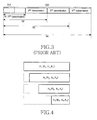
- FIG. 4 shows a process of generating a parity check matrix using a shortening scheme according to the present invention.
- H i (R i ,N i ,K i ) means a parity check matrix of a block LDPC code having a coding rate R i , a codeword length N i , and an information word length K i , and if i ⁇ j, then N i >N j and K i >K j .
- a process of changing a block LDPC code corresponding to a parity check matrix of H 1 (R 1 ,N 1 ,K 1 ) (‘(R 1 ,N 1 ,K 1 )-block LDPC code’) into a block LDPC code corresponding to a parity check matrix of H 2 (R 2 ,N 2 ,K 2 ) (‘(R 2 ,N 2 ,K 2 )-block LDPC code’) can be simply analogized assuming that first (K 1 -K 2 ) information word bits of the (R 1 ,N 1 ,K 1 )-blck LDPC code are all fixed to ‘0’.
- the (R i ,N i ,K i )-block LDPC code except for the (R 2 ,N 2 ,K 2 )-block LDPC code can also be simply generated by fixing (K 1 -K i ) information word bits of the (R 1 ,N 1 ,K 1 )-block LDPC code to ‘0’.
- a coding rate of the corresponding block LDPC code can be represented by Equation (1)
- Equation (1) Equation (1) can be rewritten as Equation (2)
- Equation (2) It can be understood from Equation (2) that the coding rate is reduced when a parity check matrix is generated using the shortening scheme.
- the parity check matrix H 1 (R 1 ,N 1 ,K 1 ) has a full rank
- the number of rows in the parity check matrix generated using the shortening scheme remains constant. Therefore, the information word length is reduced while the parity length remains constant, so the coding rate is reduced.
- the shortening scheme has a basic principle of removing the column mapped to the information word.
- the puncturing scheme increases a coding rate by transmitting only a part of the generated parity rather than transmitting the entire parity generated from an encoder, like the convolutional encoder. Although the puncturing scheme does not transmit the whole of the generated parity, it can be substantially considered that there is no change in the parity check matrix. Therefore, the puncturing scheme is different from the shortening scheme that erases the rows and columns of the parity check matrix. An operation of generating a parity check matrix using the puncturing scheme will be described below.
- Equation (3) e i and p i each mean a 1 ⁇ 43 row vector.
- Equation (4) means a codeword of a block LDPC code obtained by puncturing even blocks from the parity part corresponding to the parity.
- c punc ( u 1 , u 2 , . . . , u 20 p 1 , p 3 , p 5 , . . . , p 17 , p 19 ) (4)
- Equation (4) c punc means a codeword of the punctured block LDPC code.
- the original parity check matrix can be used as it is, by considering the punctured parity bits as erased bits. That is, if a Log-Likelihood Ratio (LLR) value input from the channel where the punctured parity bits are transmitted is always regarded as ‘0’, the original parity check matrix can be used as it is during decoding.
- LLR Log-Likelihood Ratio
- a node corresponding to the punctured parity never affects the performance improvement or performance degradation due to iterative decoding in the decoding process, and simply serves as a path where messages delivered from other nodes are transferred.
- a description will now be made of a function of a node corresponding to a parity punctured with the use of the puncturing scheme in a decoding process for a codeword of the block LDPC code generated using the puncturing scheme.
- FIGS. 5A to 5D show a function of a node corresponding to a punctured parity in a decoding process for a codeword of a block LDPC code generated using a puncturing scheme according to the present invention.
- ⁇ circle around (x) ⁇ means a node corresponding to the punctured parity
- arrows mean the directions where messages are actually delivered.
- an LLR value ‘0’ is input to a node corresponding to a punctured parity.
- a message input from the channel shown in FIG. 5A is delivered to a check node in a first decoding process, as shown in FIG. 5B .
- variable nodes are delivered to the check node connected to the input message, i.e. connected to the symbol probability value.
- the node corresponding to the parity delivers the LLR value ‘0’ to the connected check nodes.
- the check nodes perform a predetermined operation using probability values input from variable nodes connected to the check nodes to calculate the probability values to be delivered to their associated variable nodes, and delivers the calculated probability values to the corresponding variable nodes.
- the message delivered from the check node to all nodes connected to the node corresponding to the punctured parity becomes ‘0’ as shown in FIG. 5C .
- the message delivered to the node corresponding to the punctured parity is not ‘0’ and the messages delivered to the nodes corresponding to the punctured parity are delivered according to their paths without causing interference to each other, as shown in FIG. 5D .
- the following decoding process is equal to the decoding process of the general LDPC code, and the node corresponding to the punctured parity simply serves as a delivery path of the messages without continuously affecting performance improvement due to the decoding.
- the puncturing scheme when the puncturing scheme is used, the initially provided encoder and decoder can be used as they are during coding and decoding. That is, the puncturing scheme has high reliability because its coding complexity and decoding complexity are almost constant regardless of a coding rate and a block (codeword) length, and the information word length is fixed and only the parity length is changed to vary the coding rate.
- the block LDPC code generated using the puncturing scheme can differ in performance according to its puncturing pattern, so it is also very important to optimally design the puncturing pattern.
- the extending scheme reduces a coding rate by increasing the number of independent rows of the parity check matrix.
- Increasing the number of rows in the parity check matrix of the block LDPC code refers to increasing the number of check equations that the codeword should satisfy.
- An increase in the number of check equations causes a decrease in the number of codewords satisfying the check equations. Therefore, when the extending scheme is used, the number of parity bits of the block LDPC code increases in the fixed codeword length, reducing the coding rate.
- FIG. 6 shows a process of generating a parity check matrix using an extending scheme according to the present invention.
- H i (R i ,N i ,K i ) means a parity check matrix of a block LDPC code having a coding rate R i , a codeword length N i , and an information word length K i , and if i ⁇ j, then N i >N j and K i >K j .
- each of the parity check matrixes of a block LDPC code shown in FIG. 6 has a full rank M i
- a coding rate of a code generated according to each of the parity check matrixes of the block LDPC code can be expressed as Equation (5)
- Equation (5) N i denotes the number of columns of a parity check matrix, and M i denotes the number of independent rows. As shown in Equation (5), if the extending scheme is applied, the full rank M i increases for all i, so the coding rate R i decreases.
- a scheme of erasing rows on the basis of a parity check matrix having a very low coding rate like H i (R i ,N i ,K i ) may generate a parity check matrix having a high coding rate.
- the pruning scheme increases a coding rate by decreasing the number of independent rows of the parity check matrix.
- decreasing the number of rows in a parity check matrix of the block LDPC code refers to decreasing the number of check equations that the codeword should satisfy.
- a decrease in the number of the check equations causes an increase in the number of codewords satisfying the check equations. Therefore, when the pruning scheme is used, the number of parity bits decreases in the fixed codeword length, increasing the coding rate.
- FIG. 7 shows a process of generating a parity check matrix using a pruning scheme according to an embodiment of the present invention.
- H i (R i ,N i , K i ) means a parity check matrix of a block LDPC code having a coding rate R i , a codeword length N i , and an information word length K i , and if i ⁇ j, then N i >N j and K i >K j .
- the pruning scheme shown in FIG. 7 is performed in the reverse way of the extending scheme shown in FIG. 6 . Therefore, unlike the extending scheme of FIG. 6 that increases the number of parity bits in the fixed codeword length, thus reducing the coding rate, the pruning scheme decreases the number of parity bits in the fixed codeword length, thus increasing the coding rate.
- a rate-compatible block LDPC code generated using only the puncturing scheme will be described.
- the method of using only the puncturing scheme designs an LDPC code having the lowest coding rate, and creates the LDPC codes having high coding rates using only the puncturing scheme.
- a rate-compatible block LDPC code generated using the extending scheme will be described.
- the method of using only the extending scheme designs an LDPC code having the highest coding rate, and creates the LDPC codes having low coding rates using only the extending scheme.
- the method of using the puncturing scheme and the extending scheme designs an LDPC code having an intermediate coding rate, creates LDPC codes having lower coding rates using the extending scheme, and creates LDPC codes having higher coding rates using the puncturing scheme.
- the method of using the puncturing scheme and the shortening scheme designs an LDPC code having an intermediate coding rate, creates LDPC codes having lower coding rates using the shortening scheme, and creates LDPC codes having higher coding rates using the puncturing scheme.
- the methods proposed up to now first design a block LDPC code having excellent performance for a particular coding rate, and design the other codes using the puncturing scheme, the shortening scheme, the extending scheme, and the pruning scheme.
- the LDPC codes generated using these methods are inferior to the block LDPC codes having good performance for all coding rates.
- the shortening scheme inputs a known value, generally ‘0’, to particular positions of an information node in order to reduce a coding rate of an LDPC code.
- the corresponding information node is called a ‘known information node’.
- An LLR message delivered from the known information node to a check node has a positive infinite value (+ ⁇ ). That is, it can be understood from Equation (6) that the line connected from the information node to the check node is removed.
- m u log ( 1 + ⁇ i ⁇ ⁇ tanh ⁇ ⁇ 1 2 ⁇ m i 1 - ⁇ i ⁇ tanh ⁇ ⁇ 1 2 ⁇ m i ( 6 )
- Equation (6) m u denotes a message delivered from a check node to a variable node, and m i denotes a message delivered from a variable node to a check mode.
- the puncturing scheme punctures particular positions of the variable node including a parity node and an information node in order to increase a coding rate of the LDPC code.
- the puncturing scheme punctures a low-degree parity node.
- an LLR message delivered from the channel to the punctured variable node during decoding corresponds to ‘0’.
- the punctured node is included in the variable node, reliability of the message is lower than that in the case where the punctured node is not included.
- a reliability of the message of the check node decreases as the degree of the check node increases, so the puncturing scheme contributes to an increase in the degree of the check node.
- An effect of the increase in the degree of the check node may differ according to a structure of the LDPC code and its associated puncturing pattern.
- the extending scheme is a scheme of increasing a degree of the variable node in order to increase a coding rate of the LDPC code. Generally, the extending scheme increases a degree of an information node among variable nodes.
- the pruning scheme is a scheme of pruning a line connected to an independent check node among the lines connected to the variable nodes, compared with the extending scheme. Generally, the pruning scheme is performed on the information node, and a degree of the information node decreases.
- the method of using only the puncturing scheme adjusts a coding rate of the LDPC code by changing only the degree of the check node.
- the method of using only the extending scheme adjusts a coding rate of the LDPC code by changing only the degree of the variable node.
- the method of using the puncturing scheme and the extending scheme adjusts a coding rate of the LDPC code by increasing the degree of the variable node for the coding rates from the mother code, and increasing the degree of the check node for the high coding rates.
- the method of using the puncturing scheme and the shortening scheme adjusts a coding rate of the LDPC code by decreasing the degree of the check node for the low coding rates from the mother code, and increasing the degree of the check node for the high coding rates.
- the proposed rate-compatible block LDPC codes cannot be supported when the degree of the check node and the degree of the variable node are simultaneously changed.
- the degree of the check node and the degree of the variable node are simultaneously changed. Therefore, the conventional rate-compatible LDPC code suffers considerable performance degradation, when it has a wide-range coding rate that should be supported.
- the present invention provides a method for designing a rate-compatible block LDPC code that can satisfy all of the above cases.
- the present invention provides a method for designing a rate-compatible block LDPC code capable of supporting, for example, coding rates R 1 ⁇ R 2 ⁇ . . . R m with one parity check matrix.
- the present invention can be divided into, for example, the following five steps, and can design the rate-compatible block LDPC code through the steps.
- Step 1 For a coding rate R m , optimization of degree distribution is performed using a density evolution technique. Assuming that a ratio of variable nodes with a degree j (1 ⁇ j ⁇ d v,max ) to all the variable nodes is f mj in the degree distribution obtained as a result of the optimization, the f mj and the degree distribution ⁇ mj of the edge can be mutually modified using the relationship defined as Equation (7)
- Step 2 For l, m ⁇ 1, m ⁇ 2, . . . , 1, a degree distribution f lj of a variable node of a block LDPC code is found by satisfying the condition that a degree of each variable node should increase from or be matched to the degree distribution found in the previous step. However, there is no separate condition for the degree of the check node.
- a pruning pattern is generated by comparing degree distributions of individual variable nodes. A reduction in the degree of the variable node corresponds to the pruning.
- Step 3 In order to express m LDPC codes with the same parity check matrix, degrees of the check nodes should be matched. That is, in order to express m parity check matrixes with one check matrix, the number of 1's per row of m parity check matrixes should necessarily be matched, and this is equal to the process of matching the degrees of the check nodes.
- the matched degree d c of the check node can be calculated by Equation (8) below, and the calculated value becomes a degree of the check node of the rate-compatible block LDPC code. That is, m block LDPC codes are changed to m punctured LDPC codes having the degree d c of the check node without a change in the performance.
- the structured LDPC codes such as Irregular Repeat Accumulate (IRA) code, Concatenated Zigzag (CZZ) code, block LDPC code, etc.
- the d c can be calculated by Equation (8)
- d c gcd ( d c,1 ⁇ 2 ,d c,2 ⁇ 2 , . . . , d c,m ⁇ 2)+2 (8) where gcd denotes the greatest common divisor.
- the process where the LDPC code is changed to a punctured LDPC code without performance degradation can differ according to structure of the LDPC code. That is, the IRA code and the block LDPC code are different in the process.
- Step 4 The m punctured LDPC codes are combined into one rate-compatible LDPC code. Assuming that the m puncturing patterns generated in Step 3 are defined as (P 1 ) ⁇ (P 2 ) ⁇ . . . (P m ), if Condition 1 below is satisfied, performance degradation never occurs in the process where the m punctured LDPC codes are made into one rate-compatible LDPC code.
- Step 5 If Condition 1 is unsatisfied, a property of a variable coding rate is given to the m puncturing patterns generated in Step 3.
- the puncturing patterns are designed such that the conventional puncturing patterns are maintained if possible. However, Condition 2 below should be satisfied.
- the rate-compatible puncturing patterns are formed while the property of the puncturing pattern corresponding to the low coding rate is maintained if possible.
- the check node degree indicates the number of lines connected to the check nodes in the Tanner graph or biparti graph indicating an LDPC code.
- reliability of a message delivered from a check node to a variable node is higher, as a degree of the check node is lower.
- a check node degree of an LDPC code A is denoted by d c,A
- a degree of a check node of an LDPC code B is denoted by d c,B
- a degree of a check node of an LDPC code C is denoted by d c,C
- the degrees d c,A , d c,B and d c,C of the respective check nodes satisfy Equation (9) below.
- FIG. 8 shows a Tanner graph of an (8,4)-IRA code with a coding rate 1 ⁇ 2 according to one example of the present invention.
- Step 3 for an IRA code which is a structured LDPC code that is possible for fast decoding and shows good performance.
- Black circles 810 mean parity nodes
- white circles 820 information nodes
- a hatched circle 830 means a reference node always having a value ‘0’.
- the reference node as it is not a value transmitted, is excluded from coding rate calculation, and the puncturing is performed only for the parity bits.
- a puncturing pattern (p) means that the last (p ⁇ 1) parity bits are punctured every p parity bits.
- the IRA code with a check node degree lo(d c ) is equal in terms of performance to the punctured IRA code having a check node degree d c and a puncturing pattern (p).
- FIG. 9 shows a Tanner graph of a block LDPC code according to another example of the present invention.
- FIG. 9 shows a process of Step 3 for a block LDPC code, where a structure of a simple block LDPC code where the number of parity bits in a base matrix is 3 and a size of a circulant matrix is 3. Puncturing is performed only for the parity bits, and a puncturing pattern (p) indicates that the last (p ⁇ 1) parity bits are punctured every p parity bits.
- the puncturing is performed in groups.
- N q denotes the number of parity bits in a base parity check matrix of the block LDPC code
- N e denotes a size of the circulant matrix
- the parity bits in each group are equal in terms of whether they are punctured or not. That is, the punctured G(i) means that all parity bits belonging to the G(i) are punctured.
- a rate-compatible LDPC code capable of supporting coding rates 1 ⁇ 6, 3 ⁇ 8, 3 ⁇ 4 and 24/25 is designed for the IRA code, by way of example.
- an IRA code having good performance is designed for each coding rate as shown in Table 1 below.
- the design is achieved using the density evolution technique. Because the density evolution technique is a known technique, a detailed description thereof will be omitted.
- degrees of check nodes should be matched.
- the process of matching the degrees of the check nodes is essential for combining four parity check matrixes into one parity check matrix.
- the process finds a degree of a check node that should be matched, from the greatest common divisor of 1, 3, 12 and which are determined by subtracting 2 from the degree of the check node using Equation (8). That is, each code is converted into a punctured IRA code with a check node degree of gcd(1,3,12,96)+2.
- a property of a variable coding rate is given to every puncturing pattern as described above. That is, it can be understood in the foregoing embodiment that the puncturing patterns (3), (12) and (96) for the coding rates satisfy Condition 1. That is, 4 IRA codes can be expressed using a parity check matrix of one rate-compatible LDPC code, without performance degradation.
- a puncturing pattern and a pruning pattern for each coding rate will be summarized as follows.
- the LDPC code is created by puncturing 2 bits from the mother code every 3 bits.
- a pruning scheme is used which first prunes 3 lines from the mother code for the information nodes with a degree 7 to create an information node with a degree 4. For the remaining parity bits, the scheme punctures 11 parity bits every 12 bits. Of the 11 punctured bits, 2 bits include the bits punctured at the coding rate 1 ⁇ 3 of (1).
- a pruning scheme is used which prunes 3 lines from the mother code for the information nodes with a degree 7 to create an information node with a degree 4.
- the scheme punctures 95 parity bits every 96 bits.
- 11 bits include the bits punctured at the coding rate 3 ⁇ 4 of (2).
- Performance of the rate-compatible LDPC code generated through the above procedure proposed by the present invention is shown in FIG. 10 .
- the performance graph is compared with a rate-compatible turbo code (RCTC), and it can be noted that the proposed rate-compatible LDPC code is superior to the RCTC in performance.
- RCTC rate-compatible turbo code
- FIG. 11 shows a structure of a transceiver for a communication system according to the present invention.
- a transmitter 1100 includes an encoder 1101 , a puncturing and pruning unit 1103 , and a modulator 1105 , and a receiver 1150 includes a demodulator 151 , a ‘0’ inserter 1153 , and a decoder 1155 .
- the information data is delivered to the encoder 1101 .
- the encoder 1101 encodes the information data into coded symbols with a predetermined coding scheme, and outputs the coded symbols to the puncturing & pruning unit 1103 .
- the puncturing and pruning unit 1103 punctures/prunes a predetermined number of coded symbols from the symbols received from the encoder 1101 according to the coding rate information set in the system, and provides the result to the modulator 1105 . That is, the puncturing & pruning unit 1103 , as described above, performs pruning on an information node for generating an information node corresponding to a set degree from a mother code for each coding rate.
- the puncturing & pruning unit 1103 punctures a predetermined number of bits every parity bits given for each coding rate, for the parity bits left after the pruning.
- the modulator 1105 modulates the coded symbols into modulation symbols with a predetermined modulation scheme, and transmits the modulation symbols over the air via an antenna of the transmitter 1100 .
- the signal transmitted over the air by the transmitter 1100 is received over a channel via an antenna of the receiver 1150 , and the signal received via the antenna is delivered to the demodulator 1151 .
- the demodulator 1151 demodulates the signal transmitted from the transmitter 1100 with a demodulation scheme corresponding to the modulation scheme used in the modulator 1105 of the transmitter 1100 , and provides the demodulated signal to the ‘0’ inserter 1153 .
- the ‘0’ inserter 1153 inserts ‘0’s in the received information bit steam provided from the demodulator 1151 according to the coding rate information set in the system, and provides the result to the decoder 1155 .
- the decoder 1155 decodes the signal output from the ‘0’ inserter 1153 with a decoding scheme corresponding to the coding scheme used in the encoder 1101 of the transmitter 1100 , and outputs the decoded signal as the finally recovered information data.
- FIG. 12 shows a method of generating a rate-compatible block LDPC code according to the present invention.
- Five steps are shown of designing a rate-compatible block LDPC code according to the present invention.
- specific LDPC codes for example, block LDPC codes, IRA codes and CZZ codes are designed for m coding rates.
- a pruning pattern is generated by comparing information node degrees of the m LDPC codes.
- step 1205 check node degrees of the m LDPC codes are matched.
- the matched degrees of the check nodes can be calculated using Equation (8).
- m puncturing patterns are generated according to the check node degree in step 1207 .
- step 1209 it is determined whether a condition given for the generated puncturing patterns, i.e. a first condition, is satisfied. If the puncturing patterns satisfy the first condition in step 1209 , the generated puncturing patterns are determined as rate-compatible puncturing patterns in step 1211 . However, if the puncturing patterns do not satisfy the first condition in step 1209 , rate-compatible puncturing patterns are generated according to a condition given for the generated m puncturing patterns, i.e. a second condition, in step 1213 .
- a condition given for the generated puncturing patterns i.e. a first condition
- the present invention proposes a rate-compatible block LDPC code in a mobile communication system, thereby improving flexibility of a block LDPC code.
- the present invention minimizes coding complexity of a rate-compatible block LDPC code by generating an efficient parity check matrix.
- the present invention minimizes hardware complexity by facilitating generation of a block LDPC code that can be applied to various coding rates.
Landscapes
- Physics & Mathematics (AREA)
- Probability & Statistics with Applications (AREA)
- Engineering & Computer Science (AREA)
- Theoretical Computer Science (AREA)
- Error Detection And Correction (AREA)
Abstract
Description
c=(u 1, u 2, . . . , u 20
c punc=(u 1,u 2, . . . , u 20
where a degree of the check node is assumed as dc,m.
d c =gcd(d c,1−2,d c,2−2, . . . , d c,m−2)+2 (8)
where gcd denotes the greatest common divisor.
dc,A=dc,B<dc,C (9)
lo(d c,B)=d c,C >d c,A (10)
lo(d c)=(d c−2)p+2 (11)
lo(d c)=(d c−2)p G+2 (12)
Np=NeNg (13)
G(i)=(P(iN e), P(iN e+1), . . . , P((i+1)N e−1)) (14)
| TABLE 1 | |||
| Degree of | Degree of Variable | ||
| Coding Rate | Check Node | Node | Node Ratio |
| Coding Rate ⅙ | 3 | 2 | ⅚ |
| 4 | 1/18 | ||
| 7 | 2/18 | ||
| Coding Rate ⅜ | 5 | 2 | ⅝ |
| 4 | 2/8 | ||
| 7 | ⅛ | ||
| Coding Rate ¾ | 14 | 2 | ¼ |
| 4 | ¾ | ||
| |
98 | 2 | 1/25 |
| 4 | 24/25 | ||
| TABLE 2 | |||
| Degree of Check Node | Degree of Variable | Node Ratio | |
| 3 | 2 | ⅚ | |
| 4 | 1/18 | ||
| 7 | 2/18 | ||
Claims (17)
d c =gcd(d c,1−2,d c,2−2, . . . , d c,m−2)+2
d c =gcd(d c,1−2,d c,2−2, . . . , d c,m−2)+2
Applications Claiming Priority (3)
| Application Number | Priority Date | Filing Date | Title |
|---|---|---|---|
| KR89561/2005 | 2005-09-26 | ||
| KR1020050089561A KR100856235B1 (en) | 2005-09-26 | 2005-09-26 | Apparatus and method for block low density parity check code encoding / decoding having variable coding rate |
| KR10-2005-0089561 | 2005-09-26 |
Publications (2)
| Publication Number | Publication Date |
|---|---|
| US20070089025A1 US20070089025A1 (en) | 2007-04-19 |
| US7802164B2 true US7802164B2 (en) | 2010-09-21 |
Family
ID=37949514
Family Applications (1)
| Application Number | Title | Priority Date | Filing Date |
|---|---|---|---|
| US11/527,193 Active 2029-07-22 US7802164B2 (en) | 2005-09-26 | 2006-09-26 | Apparatus and method for encoding/decoding block low density parity check codes having variable coding rate |
Country Status (2)
| Country | Link |
|---|---|
| US (1) | US7802164B2 (en) |
| KR (1) | KR100856235B1 (en) |
Cited By (18)
| Publication number | Priority date | Publication date | Assignee | Title |
|---|---|---|---|---|
| US20090006906A1 (en) * | 2007-06-29 | 2009-01-01 | Noah Jacobsen | Method and system for encoding data using rate-compatible irregular LDPC codes based on edge growth and parity splitting |
| US20090113267A1 (en) * | 2007-10-31 | 2009-04-30 | Keith Harrison | Error detection method and apparatus |
| US20090228758A1 (en) * | 2008-03-05 | 2009-09-10 | Samsung Electronics Co. Ltd. | Apparatus and method for generating low density parity check code |
| US20090259913A1 (en) * | 2008-03-03 | 2009-10-15 | Samsung Electronics Co., Ltd. | Method for encoding control information in a wireless communication system using low density parity check code, and method and apparatus for transmitting and receiving the control information |
| US20100031114A1 (en) * | 2008-07-30 | 2010-02-04 | Nortel Networks Limited | Low density parity check (ldpc) decoder using broadcast messaging |
| US20100107033A1 (en) * | 2007-01-31 | 2010-04-29 | Kenichi Kuri | Radio communication device and puncturing method |
| US20110022922A1 (en) * | 2009-07-21 | 2011-01-27 | Ramot At Tel Aviv University Ltd. | Compact decoding of punctured block codes |
| US20110022927A1 (en) * | 2009-07-21 | 2011-01-27 | Ramot At Tel Aviv University Ltd. | Compact decoding of punctured codes |
| US20110022920A1 (en) * | 2009-07-21 | 2011-01-27 | Ramot At Tel Aviv University Ltd. | Compact decoding of punctured block codes |
| US20110022921A1 (en) * | 2009-07-21 | 2011-01-27 | Ramot At Tel Aviv University Ltd. | Compact decoding of punctured block codes |
| US20140229791A1 (en) * | 2013-02-08 | 2014-08-14 | Altera Corporation | Parallel decomposition of reed solomon umbrella codes |
| US9015548B2 (en) | 2010-08-30 | 2015-04-21 | Kabushiki Kaisha Toshiba | Error detection correction method and semiconductor memory apparatus |
| US9306601B2 (en) | 2013-02-13 | 2016-04-05 | Qualcomm Incorporated | LDPC design for high parallelism, low error floor, and simple encoding |
| TWI551061B (en) * | 2011-01-21 | 2016-09-21 | Sun Patent Trust | Coding method, decoding method |
| US20160323060A1 (en) * | 2015-04-28 | 2016-11-03 | Intel IP Corporation | Apparatus, computer readable medium, and method for higher qam in a high efficiency wireless local-area network |
| US10243638B2 (en) | 2016-10-04 | 2019-03-26 | At&T Intellectual Property I, L.P. | Forward error correction code selection in wireless systems |
| US10270559B2 (en) | 2016-10-04 | 2019-04-23 | At&T Intellectual Property I, L.P. | Single encoder and decoder for forward error correction coding |
| US10509603B2 (en) | 2016-07-29 | 2019-12-17 | Western Digital Technologies, Inc. | Hierarchical variable code rate error correction coding |
Families Citing this family (30)
| Publication number | Priority date | Publication date | Assignee | Title |
|---|---|---|---|---|
| KR101413320B1 (en) * | 2007-06-04 | 2014-07-02 | 포항공과대학교 산학협력단 | And apparatus for channel interleaving / deinterleaving in a communication system |
| AU2013201428B2 (en) * | 2008-02-26 | 2015-03-19 | Postech Academy Industry Foundation | Method and apparatus for channel encoding and decoding in a communication system using low-density parity-check codes |
| KR101503059B1 (en) * | 2008-02-26 | 2015-03-19 | 삼성전자주식회사 | Apparatus and method for channel encoding and decoding in communication system using low-density parity-check codes |
| KR101503058B1 (en) * | 2008-02-26 | 2015-03-18 | 삼성전자주식회사 | Method and apparatus for channel encoding / decoding in a communication system using a low-density parity-check code |
| PL2099135T3 (en) * | 2008-03-03 | 2018-07-31 | Samsung Electronics Co., Ltd. | Apparatus and method for channel encoding and decoding in communication system using low-density parity-check codes |
| US8166364B2 (en) | 2008-08-04 | 2012-04-24 | Seagate Technology Llc | Low density parity check decoder using multiple variable node degree distribution codes |
| US8601352B1 (en) * | 2009-07-30 | 2013-12-03 | Apple Inc. | Efficient LDPC codes |
| WO2011062424A2 (en) | 2009-11-18 | 2011-05-26 | Samsung Electronics Co., Ltd. | Method and apparatus for transmitting and receiving data in a communication system |
| US7990290B1 (en) | 2010-02-03 | 2011-08-02 | International Business Machines Corporation | Efficient rateless distributed compression of non-binary sources |
| KR101125100B1 (en) * | 2010-12-03 | 2012-03-21 | 한국과학기술원 | Design method of reed-solomon-based quasi-cyclic ldpc codes by puncturing, encoding/decoding method and storage device using the same |
| KR101806212B1 (en) | 2011-02-22 | 2017-12-08 | 삼성전자주식회사 | Method and apparatus for transmitting signaling information in digital broadcasting system |
| US8566667B2 (en) * | 2011-07-29 | 2013-10-22 | Stec, Inc. | Low density parity check code decoding system and method |
| US8762798B2 (en) | 2011-11-16 | 2014-06-24 | Stec, Inc. | Dynamic LDPC code rate solution |
| EP3079287B1 (en) | 2013-12-31 | 2019-10-30 | Huawei Technologies Co., Ltd. | Polar code processing method and system |
| US9602235B2 (en) | 2014-06-27 | 2017-03-21 | Texas Instruments Incorporated | Code block segmentation and configuration for concatenated turbo and RS coding |
| JP6325394B2 (en) * | 2014-08-25 | 2018-05-16 | 株式会社東芝 | IC card, portable electronic device, and IC card processing device |
| CA3207618A1 (en) | 2015-03-02 | 2016-09-09 | Samsung Electronics Co., Ltd. | Transmitter and method for generating additional parity thereof |
| KR101800414B1 (en) * | 2015-03-02 | 2017-11-23 | 삼성전자주식회사 | Transmitter and additional parity generating method thereof |
| US10784901B2 (en) | 2015-11-12 | 2020-09-22 | Qualcomm Incorporated | Puncturing for structured low density parity check (LDPC) codes |
| TWI580197B (en) * | 2016-04-27 | 2017-04-21 | 國立清華大學 | Encoding and decoding method of low density parity check code |
| KR102600952B1 (en) * | 2016-05-04 | 2023-11-13 | 삼성전자주식회사 | Transmitter and signal processing method thereof |
| US10454499B2 (en) * | 2016-05-12 | 2019-10-22 | Qualcomm Incorporated | Enhanced puncturing and low-density parity-check (LDPC) code structure |
| US10469104B2 (en) | 2016-06-14 | 2019-11-05 | Qualcomm Incorporated | Methods and apparatus for compactly describing lifted low-density parity-check (LDPC) codes |
| EP3264610A1 (en) * | 2016-06-27 | 2018-01-03 | Alcatel Lucent | Forward error correction with variable coding rate |
| US10312939B2 (en) | 2017-06-10 | 2019-06-04 | Qualcomm Incorporated | Communication techniques involving pairwise orthogonality of adjacent rows in LPDC code |
| US12476733B2 (en) | 2017-06-19 | 2025-11-18 | Qualcomm Incorporated | Communication techniques with self-decodable redundancy versions (RVs) using systematic codes |
| EP3649755B1 (en) | 2017-07-07 | 2023-09-20 | QUALCOMM Incorporated | Communication techniques applying low-density parity-check code base graph selection |
| US10848182B2 (en) | 2018-09-13 | 2020-11-24 | Apple Inc. | Iterative decoding with early termination criterion that permits errors in redundancy part |
| US11949436B2 (en) * | 2022-08-12 | 2024-04-02 | Qualcomm Incorporated | Low-density parity-check coding scheme with varying puncturing pattern |
| WO2025045213A1 (en) * | 2023-08-31 | 2025-03-06 | Mediatek Inc. | Ldpc encoding with longer codeword length and lifting matrix design thereof for next-generation wlan systems |
Citations (8)
| Publication number | Priority date | Publication date | Assignee | Title |
|---|---|---|---|---|
| KR20010037341A (en) | 1999-10-15 | 2001-05-07 | 구자홍 | Puncturing pattern search method for convolution code |
| US20040098659A1 (en) * | 2002-11-18 | 2004-05-20 | Bjerke Bjorn A. | Rate-compatible LDPC codes |
| US20040255229A1 (en) | 2003-06-13 | 2004-12-16 | Ba-Zhong Shen | Iterative metric updating when decoding LDPC (Low Density Parity Check) coded signals and LDPC coded modulation signals |
| WO2005015748A1 (en) | 2003-08-08 | 2005-02-17 | Intel Corporation | Method and apparatus for varying lengths of low density parity check codewords |
| KR20050066964A (en) | 2003-12-26 | 2005-06-30 | 한국전자통신연구원 | The method for forming parity check matrix for parallel concatenated ldpc codes |
| KR20060047842A (en) | 2004-10-27 | 2006-05-18 | 삼성전자주식회사 | How to puncture low density parity check channel code |
| KR20070009244A (en) | 2005-07-15 | 2007-01-18 | 삼성전자주식회사 | Channel Interleaving / Deinterleaving Device and Its Control Method in Communication System Using Low Density Parity Check Code |
| US7222284B2 (en) * | 2003-06-26 | 2007-05-22 | Nokia Corporation | Low-density parity-check codes for multiple code rates |
-
2005
- 2005-09-26 KR KR1020050089561A patent/KR100856235B1/en not_active Expired - Fee Related
-
2006
- 2006-09-26 US US11/527,193 patent/US7802164B2/en active Active
Patent Citations (8)
| Publication number | Priority date | Publication date | Assignee | Title |
|---|---|---|---|---|
| KR20010037341A (en) | 1999-10-15 | 2001-05-07 | 구자홍 | Puncturing pattern search method for convolution code |
| US20040098659A1 (en) * | 2002-11-18 | 2004-05-20 | Bjerke Bjorn A. | Rate-compatible LDPC codes |
| US20040255229A1 (en) | 2003-06-13 | 2004-12-16 | Ba-Zhong Shen | Iterative metric updating when decoding LDPC (Low Density Parity Check) coded signals and LDPC coded modulation signals |
| US7222284B2 (en) * | 2003-06-26 | 2007-05-22 | Nokia Corporation | Low-density parity-check codes for multiple code rates |
| WO2005015748A1 (en) | 2003-08-08 | 2005-02-17 | Intel Corporation | Method and apparatus for varying lengths of low density parity check codewords |
| KR20050066964A (en) | 2003-12-26 | 2005-06-30 | 한국전자통신연구원 | The method for forming parity check matrix for parallel concatenated ldpc codes |
| KR20060047842A (en) | 2004-10-27 | 2006-05-18 | 삼성전자주식회사 | How to puncture low density parity check channel code |
| KR20070009244A (en) | 2005-07-15 | 2007-01-18 | 삼성전자주식회사 | Channel Interleaving / Deinterleaving Device and Its Control Method in Communication System Using Low Density Parity Check Code |
Cited By (31)
| Publication number | Priority date | Publication date | Assignee | Title |
|---|---|---|---|---|
| US20100107033A1 (en) * | 2007-01-31 | 2010-04-29 | Kenichi Kuri | Radio communication device and puncturing method |
| US20090006906A1 (en) * | 2007-06-29 | 2009-01-01 | Noah Jacobsen | Method and system for encoding data using rate-compatible irregular LDPC codes based on edge growth and parity splitting |
| US7966548B2 (en) * | 2007-06-29 | 2011-06-21 | Alcatel-Lucent Usa Inc. | Method and system for encoding data using rate-compatible irregular LDPC codes based on edge growth and parity splitting |
| US8205134B2 (en) * | 2007-10-31 | 2012-06-19 | Hewlett-Packard Development Company, L.P. | Error detection method and apparatus |
| US20090113267A1 (en) * | 2007-10-31 | 2009-04-30 | Keith Harrison | Error detection method and apparatus |
| US20090259913A1 (en) * | 2008-03-03 | 2009-10-15 | Samsung Electronics Co., Ltd. | Method for encoding control information in a wireless communication system using low density parity check code, and method and apparatus for transmitting and receiving the control information |
| US8352844B2 (en) * | 2008-03-03 | 2013-01-08 | Samsung Electronics Co., Ltd | Method for encoding control information in a wireless communication system using low density parity check code, and method and apparatus for transmitting and receiving the control information |
| US20090228758A1 (en) * | 2008-03-05 | 2009-09-10 | Samsung Electronics Co. Ltd. | Apparatus and method for generating low density parity check code |
| US8296636B2 (en) * | 2008-03-05 | 2012-10-23 | Samsung Electronics Co., Ltd. | Apparatus and method for generating low density parity check code |
| US20100031114A1 (en) * | 2008-07-30 | 2010-02-04 | Nortel Networks Limited | Low density parity check (ldpc) decoder using broadcast messaging |
| US8230294B2 (en) * | 2008-07-30 | 2012-07-24 | Ciena Corporation | Low density parity check (LDPC) decoder using broadcast messaging |
| US20110022927A1 (en) * | 2009-07-21 | 2011-01-27 | Ramot At Tel Aviv University Ltd. | Compact decoding of punctured codes |
| US20110022921A1 (en) * | 2009-07-21 | 2011-01-27 | Ramot At Tel Aviv University Ltd. | Compact decoding of punctured block codes |
| US20110022920A1 (en) * | 2009-07-21 | 2011-01-27 | Ramot At Tel Aviv University Ltd. | Compact decoding of punctured block codes |
| US20110022922A1 (en) * | 2009-07-21 | 2011-01-27 | Ramot At Tel Aviv University Ltd. | Compact decoding of punctured block codes |
| US8375278B2 (en) | 2009-07-21 | 2013-02-12 | Ramot At Tel Aviv University Ltd. | Compact decoding of punctured block codes |
| US8516352B2 (en) | 2009-07-21 | 2013-08-20 | Ramot At Tel Aviv University Ltd. | Compact decoding of punctured block codes |
| US8516351B2 (en) | 2009-07-21 | 2013-08-20 | Ramot At Tel Aviv University Ltd. | Compact decoding of punctured block codes |
| US9397699B2 (en) * | 2009-07-21 | 2016-07-19 | Ramot At Tel Aviv University Ltd. | Compact decoding of punctured codes |
| US9015548B2 (en) | 2010-08-30 | 2015-04-21 | Kabushiki Kaisha Toshiba | Error detection correction method and semiconductor memory apparatus |
| TWI551061B (en) * | 2011-01-21 | 2016-09-21 | Sun Patent Trust | Coding method, decoding method |
| US8977938B2 (en) * | 2013-02-08 | 2015-03-10 | Altera Corporation | Parallel decomposition of Reed Solomon umbrella codes |
| US20140229791A1 (en) * | 2013-02-08 | 2014-08-14 | Altera Corporation | Parallel decomposition of reed solomon umbrella codes |
| US9306601B2 (en) | 2013-02-13 | 2016-04-05 | Qualcomm Incorporated | LDPC design for high parallelism, low error floor, and simple encoding |
| US20160323060A1 (en) * | 2015-04-28 | 2016-11-03 | Intel IP Corporation | Apparatus, computer readable medium, and method for higher qam in a high efficiency wireless local-area network |
| US10509603B2 (en) | 2016-07-29 | 2019-12-17 | Western Digital Technologies, Inc. | Hierarchical variable code rate error correction coding |
| US10243638B2 (en) | 2016-10-04 | 2019-03-26 | At&T Intellectual Property I, L.P. | Forward error correction code selection in wireless systems |
| US10270559B2 (en) | 2016-10-04 | 2019-04-23 | At&T Intellectual Property I, L.P. | Single encoder and decoder for forward error correction coding |
| US10666339B2 (en) | 2016-10-04 | 2020-05-26 | At&T Intellectual Property I, L.P. | Forward error correction code selection in wireless systems |
| US10700813B2 (en) | 2016-10-04 | 2020-06-30 | At&T Intellectual Property I, L.P. | Single encoder and decoder for forward error correction coding |
| US10979124B2 (en) | 2016-10-04 | 2021-04-13 | At&T Intellectual Property I, L.P. | Forward error correction code selection in wireless systems |
Also Published As
| Publication number | Publication date |
|---|---|
| KR100856235B1 (en) | 2008-09-03 |
| US20070089025A1 (en) | 2007-04-19 |
| KR20070034904A (en) | 2007-03-29 |
Similar Documents
| Publication | Publication Date | Title |
|---|---|---|
| US7802164B2 (en) | Apparatus and method for encoding/decoding block low density parity check codes having variable coding rate | |
| US7502987B2 (en) | Apparatus and method for encoding and decoding block low density parity check codes with a variable coding rate | |
| US7747929B2 (en) | Apparatus and method for coding/decoding block low density parity check code with variable block length | |
| JP4291372B2 (en) | Channel encoding / decoding apparatus and method using parallel concatenated low density parity check code | |
| US7814393B2 (en) | Apparatus and method for coding/decoding block low density parity check code with variable block length | |
| US7516391B2 (en) | Apparatus and method for coding/decoding block low density parity check code with variable block length | |
| US7526717B2 (en) | Apparatus and method for coding and decoding semi-systematic block low density parity check codes | |
| US7222284B2 (en) | Low-density parity-check codes for multiple code rates | |
| US7954033B2 (en) | Decoding apparatus and method in a communication system using low density parity check codes | |
| US20060036927A1 (en) | Apparatus and method for encoding and decoding a block low density parity check code | |
| US20080028281A1 (en) | Encoding method, decoding method, and devices for same | |
| KR20050046471A (en) | Apparatus for encoding/decoding using parallel concatenation low density parity check code and the method thereof | |
| US8230299B2 (en) | Interleaving scheme for an LDPC coded QPSK/8PSK system | |
| US20070162822A1 (en) | Apparatus and method for transmitting/receiving signal supporting variable coding rate in a communication system | |
| US20060190801A1 (en) | Apparatus and method for generating low density parity check code using zigzag code in a communication system | |
| US20110307754A1 (en) | family of ldpc codes for video broadcasting applications | |
| EP1901434A1 (en) | An interleaving scheme for a LDPC coded 16APSK system | |
| US8301960B2 (en) | Interleaving scheme for an LDPC coded 32 APSK system | |
| CN101150551B (en) | Interweaving scheme of QPSK/8PSK system for low-density checksum coding | |
| CN101150378A (en) | Interleaving Scheme of LDPC 32APSK System | |
| EP1901438A2 (en) | An interleaving scheme for a LDPC coded QPSK/8PSK system |
Legal Events
| Date | Code | Title | Description |
|---|---|---|---|
| AS | Assignment |
Owner name: SAMSUNG ELECTRONICS CO., LTD., KOREA, REPUBLIC OF Free format text: ASSIGNMENT OF ASSIGNORS INTEREST;ASSIGNORS:HONG, SONG-NAM;KANG, HYUN-JEONG;SON, JUNG-JE;AND OTHERS;REEL/FRAME:018355/0917 Effective date: 20060926 |
|
| STCF | Information on status: patent grant |
Free format text: PATENTED CASE |
|
| FEPP | Fee payment procedure |
Free format text: PAYOR NUMBER ASSIGNED (ORIGINAL EVENT CODE: ASPN); ENTITY STATUS OF PATENT OWNER: LARGE ENTITY |
|
| FPAY | Fee payment |
Year of fee payment: 4 |
|
| MAFP | Maintenance fee payment |
Free format text: PAYMENT OF MAINTENANCE FEE, 8TH YEAR, LARGE ENTITY (ORIGINAL EVENT CODE: M1552) Year of fee payment: 8 |
|
| MAFP | Maintenance fee payment |
Free format text: PAYMENT OF MAINTENANCE FEE, 12TH YEAR, LARGE ENTITY (ORIGINAL EVENT CODE: M1553); ENTITY STATUS OF PATENT OWNER: LARGE ENTITY Year of fee payment: 12 |