US7798317B2 - Reamed paper shipping and display container - Google Patents
Reamed paper shipping and display container Download PDFInfo
- Publication number
- US7798317B2 US7798317B2 US11/445,446 US44544606A US7798317B2 US 7798317 B2 US7798317 B2 US 7798317B2 US 44544606 A US44544606 A US 44544606A US 7798317 B2 US7798317 B2 US 7798317B2
- Authority
- US
- United States
- Prior art keywords
- container
- base portion
- lid portion
- blank
- items
- Prior art date
- Legal status (The legal status is an assumption and is not a legal conclusion. Google has not performed a legal analysis and makes no representation as to the accuracy of the status listed.)
- Active, expires
Links
Images


Classifications
-
- B—PERFORMING OPERATIONS; TRANSPORTING
- B65—CONVEYING; PACKING; STORING; HANDLING THIN OR FILAMENTARY MATERIAL
- B65D—CONTAINERS FOR STORAGE OR TRANSPORT OF ARTICLES OR MATERIALS, e.g. BAGS, BARRELS, BOTTLES, BOXES, CANS, CARTONS, CRATES, DRUMS, JARS, TANKS, HOPPERS, FORWARDING CONTAINERS; ACCESSORIES, CLOSURES, OR FITTINGS THEREFOR; PACKAGING ELEMENTS; PACKAGES
- B65D5/00—Rigid or semi-rigid containers of polygonal cross-section, e.g. boxes, cartons or trays, formed by folding or erecting one or more blanks made of paper
- B65D5/32—Rigid or semi-rigid containers of polygonal cross-section, e.g. boxes, cartons or trays, formed by folding or erecting one or more blanks made of paper having bodies formed by folding and interconnecting two or more blanks each blank forming a body part, whereby each body part comprises at least one outside face of the box, carton or tray
- B65D5/322—Rigid or semi-rigid containers of polygonal cross-section, e.g. boxes, cartons or trays, formed by folding or erecting one or more blanks made of paper having bodies formed by folding and interconnecting two or more blanks each blank forming a body part, whereby each body part comprises at least one outside face of the box, carton or tray at least one container body part formed by folding a single blank to essentially U-shape with or without extensions which form openable lid elements
- B65D5/324—Rigid or semi-rigid containers of polygonal cross-section, e.g. boxes, cartons or trays, formed by folding or erecting one or more blanks made of paper having bodies formed by folding and interconnecting two or more blanks each blank forming a body part, whereby each body part comprises at least one outside face of the box, carton or tray at least one container body part formed by folding a single blank to essentially U-shape with or without extensions which form openable lid elements at least two container body parts, each formed by folding a single blank to essentially U-shape
Definitions
- the present invention relates to containers for shipping, storing and displaying a plurality of items such as pre-wrapped reams of cut-sized paper. More particularly, the present invention relates to a container for shipping, storing and displaying a plurality of items such as pre-wrapped reams of cut-sized paper, wherein the container is adapted to remain sealed securely during shipping yet may be opened easily for point-of-sale display and purchase.
- a container according to the present invention is sized to hold a limited number of wrapped reams of paper and has a carry handle for convenience in handling the container.
- Cut-sized paper such as conventional photocopy paper
- reams typically is wrapped in reams containing, for example, 500 sheets.
- a plurality of reams to be bundled together and shipped in a corrugated container.
- two stacks of five reams of paper to be placed in a side-by-side relationship within a conventional corrugated container base having high sidewalls.
- Several containers are then stacked on top of one another during shipping. It is desirable therefore to provide a container suitable for shipping a plurality of items, wherein the container is stackable for easy shipping, handling, storing and display.
- ancillary securing devices such as straps and the like, rather than adhesive, to hold such container lids onto their respective bases.
- ancillary securing devices such as straps and the like, rather than adhesive, to hold such container lids onto their respective bases.
- such devices do not always prevent the lids from becoming disassociated from the bases.
- the straps are loosened and are free to slip off of the container either partially or entirely, allowing the lids to become disassociated from the bases, resulting in product spillage and/or damage.
- the free straps may likewise become entangled in the material handling equipment, resulting in machine shut downs and shipping inefficiencies. Operator safety is also reduced, as the free straps and free lids clutter the workspace. It is desirable therefore to provide a container suitable for shipping a plurality of items, wherein the container is adapted to remain sealed during typical shipping, handling and storing operations without the need to utilize ancillary securing devices such as straps, and the like.
- a container for shipping a plurality of items, such as pre-wrapped reams of cut-sized paper, more particularly, a container for shipping items is provided, comprising: a base portion sized to receive a plurality of items therein; a lid portion sized to fit over the base portion, thereby at least partially enclosing the plurality of items therein; wherein at least a portion of either the base portion or the lid portion includes a break-away section for at least partially opening the container to permit removal of at least one of the plurality of items therefrom.
- a container for shipping, storing and displaying wrapped reams of paper is sized to hold a limited number of reams, thereby making it lighter in weight than conventional packages of wrapped reams of paper, and is provided with an apparatus, such as a carry handle, to facilitate handling of the container.
- an apparatus such as a carry handle
- ream of paper normally includes about 500 sheets of paper and typically weighs about five pounds each. Conventional containers that hold ten reams of paper, therefore, weigh about 50 pounds.
- a container according to one aspect of the present invention preferably holds no more than six reams of paper, such that the container would weigh about 30 pounds.
- a container according to the present invention can be sized, shaped and configured to hold one, two, three, four, five, six, or any other number of, reams of paper in any orientation, such as, for example, single stack/row or multiple stacks/rows.
- the weight of the container (having multiple reams therein) would not exceed 35 pounds.
- a container according to various aspects of the present invention is formed from two pieces of foldable paperboard material comprising a base portion and a lid portion, and is adapted to remain sealed during typical shipping, handling and storing operations without the need to utilize ancillary securing devices such as straps or the like.
- FIG. 1 is a plan view of a first blank used to form a base portion of a container according to one embodiment of the present invention
- FIG. 2 is a plan view of a second blank used to form a lid portion of a container according to one embodiment of the present invention
- FIG. 3 is an exploded perspective view of the first blank of FIG. 1 , shown folded to form a base portion of a container according to one embodiment of the present invention, and of the second blank of FIG. 2 , shown folded to form a lid portion of a container according to one embodiment of the present invention, wherein the base portion is shown filled with a plurality of items, and wherein the lid portion is shown in spaced relation to the base portion;
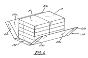
- FIG. 4 is a perspective view of the first blank of FIG. 1 , showing a first step used to form the base portion of the container shown in FIG. 3 , wherein the first and second sidewalls of the first blank are folded relative to a basewall thereof;
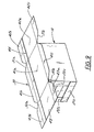
- FIG. 5 is a perspective view of the first blank of FIG. 1 , showing the first and second sidewalls of the first blank adjacent a plurality of items stored therein;
- FIG. 6 is a perspective view of the first blank of FIG. 1 , showing a second step used to form the base portion of the container shown in FIG. 3 , wherein first sidewall flaps are folded relative to the sidewalls;
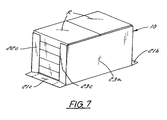
- FIG. 7 is a perspective view of the first blank of FIG. 1 , showing a third step used to form the base portion of the container shown in FIG. 3 , wherein second sidewall flaps are folded relative to the sidewalls;
- FIG. 8 is a perspective view of the first blank of FIG. 1 , showing a fourth step used to form the base portion of the container shown in FIG. 3 , wherein basewall flaps are folded relative to the basewall and adhered to base portion sidewalls;
- FIG. 9 is a perspective view of the second blank of FIG. 2 , showing the second blank being positioned over the base portion of the container shown in FIG. 3 ;
- FIG. 10 is a perspective view of the second blank of FIG. 2 , showing a first step used to form the lid portion of the container shown in FIG. 3 , wherein first and second endwalls are folded relative to the topwall;
- FIG. 11 is a perspective view of the second blank of FIG. 2 , showing a second step used to form the lid portion of the container shown in FIG. 3 , wherein lid portion endwalls are adhered to base portion sidewall flaps, and wherein lid portion sidewall flaps are folded relative to the topwall and adhered to base portion sidewalls;
- FIG. 12 is a perspective view of the second blank of FIG. 2 , showing a third step used to form a lid portion of the container shown in FIG. 3 , wherein lid portion endwall flaps are folded relative to lid portion endwalls and adhered to base portion sidewalls;
- FIG. 13 is a perspective view of a container according to one embodiment of the present invention, showing one sidewall thereof being partially detached and in an open position;
- FIG. 14 is a plan view of a first blank used to form a base portion of a container according to one alternative embodiment of the present invention.
- FIG. 15 is a plan view of a second blank used to form a lid portion of a container according to one alternative embodiment of the present invention.
- FIG. 16 is an exploded perspective view of the first blank of FIG. 14 , shown folded to form a base portion of a container according to one alternative embodiment of the present invention, and of the second blank of FIG. 15 , shown folded to form a lid portion of a container according to one alternative embodiment of the present invention, wherein the base portion is shown filled with a plurality of items, and wherein the lid portion is shown in spaced relation to the base portion;
- FIG. 17 is a plan view of a blank used to form a lid portion of a container according to another embodiment of the present invention.
- FIG. 18 is a top perspective view of a reduced sized container with a carry handle according to an alternative embodiment of the present invention.
- FIG. 19 is a top perspective view of the container of FIG. 18 , wherein the container is shown lying on its side or base and wherein a tear strip is shown partially removed to separate one side of the container from the remainder thereof to expose reams of paper contained therein;
- FIG. 20 is a top perspective view of the container of FIG. 19 , wherein a side of the container is shown fully removed therefrom, further exposing the reams of paper contained therein;
- FIG. 21 a is a top perspective view of one alternative embodiment of the present invention.
- FIG. 21 b is a top perspective view of another alternative embodiment of the present invention.
- FIG. 21 c is a top perspective view of yet another alternative embodiment of the present invention.
- FIG. 22 is a plan view of a blank for forming a base portion of the container shown in FIG. 18 ;
- FIG. 23 is a plan view of a blank for forming a lid portion of the container shown in FIG. 18 ;
- FIG. 24 is a top perspective view of a handle assembly for use in connection with a container according to any embodiment of the present invention.
- FIG. 25 is a plan view of the blank shown in FIG. 1 , wherein a strip of tear tape is shown extending across at least a portion of a center section thereof;
- FIG. 26 is a plan view of a blank used to form either a lid portion or a base portion of a container according to yet another alternative embodiment of the present invention.
- FIG. 27 is a plan view of a blank used to form a base portion of a container according to still another alternative embodiment of the present invention.
- FIG. 28 is a plan view of a blank used to form a lid portion of a container according to an embodiment of the present invention for which the base portion of FIG. 27 is used;
- FIG. 29 is a plan view of a blank used to form a base portion of a container according to still yet another alternative embodiment of the present invention.
- FIG. 30 is a plan view of a lid portion of a container according to an embodiment of the present invention for which the base portion of FIG. 29 is used.
- a first blank B 1 is provided to form a base portion 10 ( FIG. 3 ) of the container 1 ( FIG. 3 ) according to one embodiment of the present invention.
- the first blank B 1 is formed from a sheet of foldable material such as corrugated paperboard or the like and is generally rectangular in shape.
- First blank B 1 is divided by fold lines, score lines and slits to define panels which are foldable relative to one another (as described in greater detail below) to form the base portion 10 of the container 1 according to one embodiment of the present invention.
- First blank B 1 is divided into a basewall panel 21 and first and second sidewall panels 22 , 23 by a pair of transverse foldlines 11 , 12 (shown in phantom lines), which are shown to be generally parallel to one another, although transverse foldlines 11 , 12 may be oriented at some angle relative to one another.
- Slots 11 a , 11 b , 12 a , 12 b are cut into the first blank B 1 at opposite ends of the foldlines 11 , 12 , respectively.
- Slots 11 a , 11 b , 12 a , 12 b each preferably are tapered (for reasons to be described in greater detail below), but may take on any shape that might facilitate the purposes therefor.
- First blank B 1 further includes a pair of longitudinal foldlines 13 , 14 (shown in phantom lines), which are shown to be generally parallel to one another and perpendicular to transverse foldlines 11 , 12 , although longitudinal foldlines 13 , 14 may be oriented at some angle relative to one another or relative to transverse foldlines 11 , 12 .
- Longitudinal foldlines 13 , 14 divide basewall panel 21 into a center section 21 a and flanking basewall flaps 21 b , 21 c that are foldable relative to the basewall center section 21 a along longitudinal foldlines 13 , 14 , respectively.
- longitudinal foldlines 13 , 14 divide first and second sidewall panels 22 , 23 into respective center sections 22 a , 23 a , first sidewall flaps 22 b , 23 b and second sidewall flaps 22 c , 23 c , all of which are foldable relative to their respective sidewall panels 22 , 23 along longitudinal foldlines 13 , 14 , respectively.
- each of the basewall flaps 21 b , 21 c may be provided with a crushed region 24 a , 24 b , 24 c , 24 d that may be formed by compressing the blank B 1 such that the crushed regions 24 a , 24 b , 24 c , 24 d have a thickness that is less than the thickness of the first blank B generally.
- the ends of the sidewall flaps 22 b , 23 b , 22 c , 23 c nearest their respective basewall flaps 21 b , 21 c may be provided with a crushed region 25 a , 25 b , 25 c , 25 d that may be formed by compressing the blank B 1 such that the crushed regions 25 a , 25 b , 25 c , 25 d have a thickness that is less than the thickness of the first blank B 1 generally.
- the purpose and function of the crushed regions 24 a , 24 b , 24 c , 24 d , 25 a , 25 b , 25 c , 25 d will be described in greater detail below.
- Crushed regions 24 a , 24 b , 24 c , 24 d may be delimited by perforation, score or weakened lines 26 a , 26 b , 26 c , 26 d (shown in dashed lines) extending from each of the longitudinal foldlines 13 , 14 to the outer edges of basewall flaps 21 b , 21 c , respectively.
- perforation, score or weakened lines 26 a , 26 b , 26 c , 26 d shown in dashed lines
- the purpose and function of the perforation lines 26 a , 26 b , 26 c , 26 d will be described in greater detail below.
- a second blank B 2 is provided to form a lid portion 30 ( FIG. 3 ) of the container 1 ( FIG. 3 ) according to one embodiment of the present invention.
- the second blank B 2 is formed from a sheet of foldable material such as corrugated paperboard or the like and is generally rectangular in shape. Second blank B 2 is divided by fold lines, score lines and slits to define panels which are foldable relative to one another (as described in greater detail below) to form the lid portion 30 of the container 1 according to one embodiment of the present invention.
- Second blank B 2 is divided into a topwall panel 41 and first and second endwall panels 42 , 43 by a pair of transverse foldlines 31 , 32 (shown in phantom lines), which are shown to be generally parallel to one another, although transverse foldlines 31 , 32 may be oriented at some angle relative to one another.
- V-shaped cutouts 31 a , 31 b , 32 a , 32 b are cut into the second blank B 2 at opposite ends of the foldlines 31 , 32 , respectively. Cutouts 31 a , 31 b , 32 a , 32 b each preferably are tapered (for reasons to be described in greater detail below), but may take on any shape that might facilitate the purposes therefor.
- Second blank B 2 further includes a pair of longitudinal foldlines 33 , 34 (shown in phantom lines), which are shown to be generally parallel to one another and perpendicular to transverse foldlines 31 , 32 , although longitudinal foldlines 33 , 34 may be oriented at some angle relative to one another or relative to transverse foldlines 31 , 32 .
- Longitudinal foldlines 33 , 34 divide topwall panel 41 into a center section 41 a and flanking topwall flaps 41 b , 41 c that are foldable relative to the topwall center section 41 a along longitudinal foldlines 33 , 34 , respectively.
- longitudinal foldlines 33 , 34 divide first and second endwall panels 42 , 43 into respective center sections 42 a , 43 a , first endwall flaps 42 b , 43 b and second endwall flaps 42 c , 43 c , all of which are foldable relative to their respective endwall panels 42 , 43 along longitudinal foldlines 33 , 34 , respectively.
- a tearstrip 45 is embedded in the second blank B 2 or affixed to one surface thereof using conventional forming and attaching techniques. Tearstrip 45 preferably extends the entire length of the second blank B 2 parallel to first longitudinal foldline 33 spaced therefrom, although tearstrip 45 may extend only partially along the length of the second blank B 2 and may be positioned axially at any location therealong. Pull tabs 46 a , 46 b may be formed in one or both of the side edges of the second blank B 2 near terminal ends of the tearstrip 45 so as to permit gripping of at least one of the pull tabs 46 a , 46 b by a user and tearing of the tearstrip 45 utilizing conventional opening techniques.
- Tearstrip 45 preferably is provided nearer the first longitudinal foldline 33 , although tearstrip 45 may alternatively be provided nearer the second longitudinal foldline 34 . Alternatively still, two or more tearstrips may be provided and spaced from first and second foldlines ( FIG. 17 ).
- a plurality of items R such as pre-wrapped reams of cut-sized paper are arranged in two (2) vertical stacks of five (5) reams, wherein the stacks are oriented in a side-by-side relationship.
- First and second blanks B 1 , B 2 are sized such that, when folded as described herein, base portion 10 and lid portion 30 of the container 1 tightly surround and contain the stacks.
- base portion 10 is formed by first folding sidewall panels 22 , 23 upward relative to the basewall 21 along transverse foldlines 11 , 12 , respectively, such that sidewall panels 22 , 23 are generally perpendicular to the basewall 21 . Thereafter, sidewall flaps 22 b , 22 c and sidewall flaps 23 b , 23 c each are folded inwardly towards one another relative to sidewall panels 22 a , 23 a , respectively, about longitudinal foldlines 13 , 14 , respectively, to form vertically-oriented base portion corners of the container 1 .
- Basewall flaps 21 b , 21 c are folded upwardly relative to the basewall center section 21 a along longitudinal foldlines 13 , 14 , respectively, and over sidewall flaps 22 b , 23 b and 22 c , 23 c , respectively, such that crushed regions 26 a , 26 b , 26 c , 26 d lie over and are adhesively secured to crushed regions 25 a , 25 b , 25 c , 25 d , respectively.
- adhesively secure crushed regions alternative means of affixing the crushed regions as described herein, such as by staples, and the like, may be employed.
- the container 1 does not bulge near the crushed regions 25 a , 25 b , 25 c , 25 , 26 a , 26 b , 26 c , 26 d.
- Lid portion 30 is formed by first folding endwall panels 42 a , 43 a downward relative to the topwall 41 along transverse foldlines 31 , 32 , respectively, such that endwall panels 42 , 43 are generally perpendicular to the topwall 41 . Thereafter, endwall flaps 42 b , 42 c and endwall flaps 43 b , 43 c each are folded inwardly towards one another relative to endwall panels 42 a , 43 a , respectively, about longitudinal foldlines 33 , 34 , respectively, to form vertically-oriented lid portion corners of the container 1 which lie outside base portion corners when the lid portion 30 is positioned thereover.
- Topwall flaps 41 b , 41 c are folded downwardly relative to the topwall center section 41 a along longitudinal foldlines 33 , 34 , respectively.
- V-shaped cutouts 31 a , 31 b , 32 a , 32 b permit topwall flaps 41 b , 41 c to lie generally in the same plane as endwall flaps 42 b , 43 b and endwall flaps 42 c , 43 c , respectively, without overlapping.
- Lid portion 30 is telescopingly fit over the base portion 10 to define a fully-enclosed container 1 ( FIG. 12 ).
- Tearstrip 45 is positioned preferably to be adjacent one or more of the perforation lines 26 a , 26 b , 26 c , 26 d , for the purpose and function described in greater detail below.
- Lid portion flaps 41 b , 42 b , 43 b and flaps 41 c , 42 c , 43 c are adhesively affixed to the sidewall panels 22 a , 23 a , respectively, so that the lid portion 30 is adhesively affixed to the base portion 10 with sufficient adhesive strength to prevent disassociation of the lid portion 30 from the base portion 10 .
- Outwardly facing surfaces of the base portion flaps 21 b , 22 b , 23 b and flaps 21 c , 22 c , 23 c may also be adhesively affixed to inwardly facing surfaces of the lid portion endwall panels 42 a , 43 a , respectively, to further strengthen the adhesive bond between the lid portion 30 and the base portion 10 , thereby forming a fully-enclosed container having sufficient rigidity to resist compression due to vertical stacking of several containers 1 on top of one another. It will be apparent to those of ordinary skill in the art upon reading the within disclosure that a container 1 according to one embodiment of the present invention meets each of the objectives thereof.
- FIGS. 4-12 more specifically illustrate one method of automatedly forming a container 1 according to one embodiment of the present invention for the purpose of packaging a plurality of items R stored therein. More specifically, FIG. 4 shows a first step for packaging a plurality of items R wherein the plurality of items are stacked in a side-by-side relationship above the basewall center section 21 a of the first blank B 1 . It can be seen from FIG. 4 that the surface area of basewall center section 21 a is approximately equal to the combined surface area “footprint” of the stacks of items R such that the base portion 10 of the container 1 can be formed tightly around the stacks of items R.
- FIG. 5 illustrates the base portion 10 being thus partially formed around the stacks of items R.
- flaps 21 b , 22 b , 23 b and flaps 21 c , 22 c , 23 c are folded inwardly relative to their respective sidewall panels 22 , 23 so as to fold “around” distal ends of the stacks of items R, thereby forming vertical corners to the bottom portion 10 of the container 1 .
- crushed regions overlie one another and are adhesively secured to one another so as to define a self-standing, upright bottom portion 10 of the container 1 .
- FIG. 9 shows a next step for forming a container 1 according to one embodiment of the present invention, wherein the topwall panel center section 41 a of the second blank B 2 is positioned over the stack of items. It can be seen from FIG. 4 that the surface area of topwall center section 41 a is approximately equal to the combined surface area “footprint” of the stacks of items R such that the lid portion 30 of the container 1 can be formed tightly around the stacks of items R.
- FIG. 11 illustrates the lid portion 30 being thus partially formed around the stacks of items R.
- flaps 41 b , 42 b , 43 b and flaps 41 c , 42 c , 43 c are folded inwardly relative to their respective endwall panels 42 , 43 so as to fold “around” distal ends of the stacks of items R, thereby overlapping the vertical corners defined by the bottom portion 10 of the container 1 .
- V-shaped cutouts 31 a , 32 a and 31 b , 32 b allow for flaps 41 a , 42 a , 43 a and flaps 41 b , 42 b , 43 b to meet along edges of the V-shaped cutouts 31 a , 32 a , 31 b , 32 b to meet at upper corners of the container 1 without overlapping one another.
- flaps 41 b , 42 b , 43 b and flaps 41 c , 42 c , 43 c are secured (such as, by adhesive) to their respective sidewall panels 22 , 23 of the bottom portion 10 of the container 1 , so as to secure the lid portion 30 firmly to the bottom portion 10 , thereby defining a tight enclosure for securely transporting the items R packed therein.
- the second blank B 2 it is preferred to apply some downward pressure to the second blank B 2 , as it is positioned over the stacks of items R and prior to securing the top portion 30 to the bottom portion 10 so that items R are compressed somewhat so as to prevent the creation of void space within the container 1 during shipping, such as may be created, for example, if the lid portion 30 were secured to the base portion 10 prior to the escape of any entrapped air from within the items R.
- the container 1 is configured to provide a shelf-ready display package, suitable for at least partially opening and placing directly on a product shelf for point-of-sale display.
- tearstrip 45 is used (such as by gripping one of the pull tabs 46 a , 46 b and pulling same away from the container 1 ) to open one side of the container 1 , thereby exposing the ends of the items R packaged therein.
- the tearstrip 45 functions to separate a break-away section 48 of the lid 30 from the remaining portion of the container 1 .
- Perforations 26 a , 26 b , 26 c , 26 d provided in the base portion 10 then, can be torn to allow the break-away section 48 to pivot freely relative to the basewall panel 21 a .
- a scoreline (not shown) may be provided in the basewall panel 21 a , for example, extending between perforation 26 a and perforation 26 c , thereby facilitating easy rotational movement of the break-away section 48 relative to the remaining portion of the container 1 .
- the scoreline may be a perforation or another tear strip (not shown) which would allow a user to detach the break-away section 48 altogether from the remaining portion of the container 1 .
- a first alternative blank B 1 ′ is provided to form a base portion 110 ( FIG. 16 ) of the container 101 ( FIG. 16 ) according to another embodiment of the present invention.
- the first alternative blank B 1 ′ is formed from a sheet of foldable material such as corrugated paperboard or the like and is generally rectangular in shape.
- First alternative blank B 1 ′ is divided by fold lines, score lines and slits to define panels which are foldable relative to one another (as described in greater detail herein) to form the base portion 110 of the container 101 .
- First alternative blank B 1 ′ is divided into a basewall panel 121 and first and second sidewall panels 122 , 123 by a pair of transverse foldlines 111 , 112 (shown in phantom lines), which are shown to be generally parallel to one another, although transverse foldlines 111 , 112 may be oriented at some angle relative to one another.
- Slots 111 a , 111 b , 112 a , 112 b are cut into the first alternative blank B 1 ′ at opposite ends of the foldlines 111 , 112 , respectively.
- Slots 111 a , 111 b , 112 a , 112 b each may be tapered (although are shown in the Figure to be generally straight), but may take on any shape that might facilitate the purposes therefor.
- First alternative blank B 1 ′ further includes a pair of longitudinal foldlines 113 , 114 (shown in phantom lines), which are shown to be generally parallel to one another and perpendicular to transverse foldlines 111 , 112 , although longitudinal foldlines 113 , 114 may be oriented at some angle relative to one another or relative to transverse foldlines 111 , 112 .
- Longitudinal foldlines 113 , 114 divide basewall panel 121 into a center section 121 a and flanking basewall flaps 121 b , 121 c that are foldable relative to the basewall center section 121 a along longitudinal foldlines 113 , 114 , respectively.
- longitudinal foldlines 113 , 114 divide first and second sidewall panels 122 , 123 into respective center sections 122 a , 123 a , first sidewall flaps 122 b , 123 b and second sidewall flaps 122 c , 123 c , all of which are foldable relative to their respective sidewall panels 122 , 123 along longitudinal foldlines 113 , 114 , respectively.
- each of the basewall flaps 121 b , 121 c may be provided with a crushed region 124 a , 124 b , 124 c , 124 d that may be formed by compressing the blank B 1 ′ such that the crushed regions 124 a , 124 b , 124 c , 124 d have a thickness that is less than the thickness of the first alternative blank B 1 ′ generally.
- the ends of the sidewall flaps 122 b , 123 b , 122 c , 123 c nearest their respective basewall flaps 121 b , 121 c may be provided with a crushed region 125 a , 125 b , 125 c , 125 d that may be formed by compressing the blank B 1 ′ such that the crushed regions 125 a , 125 b , 125 c , 125 d have a thickness that is less than the thickness of the first alternative blank B 1 ′ generally.
- crushed regions 124 a , 124 b , 124 c , 124 d , 125 a , 125 b , 125 c , 125 d will be obvious to one of ordinary skill in the art upon reading the within description.
- the present embodiment differs from the embodiment hereof shown in FIG. 1 in that the center section 121 a of the basewall panel 121 is provided with a scoreline 148 running generally parallel to foldlines 111 , 112 and extending between foldlines 113 , 114 .
- the scoreline 148 .
- Perforation lines 149 a , 149 b extend beyond the terminal ends of the scoreline 148 , through first and second basewall flaps 121 b , 121 c , respectively.
- a plurality of scorelines may be provided for the purpose and function described in greater detail below.
- a second alternative blank B 2 ′ is provided to form a lid portion 130 ( FIG. 16 ) of the container 101 ( FIG. 16 ) for use, for example, with the first alternative blank B 1 ′ shown in FIG. 14 .
- the second alternative blank B 2 ′ is formed from a sheet of foldable material such as corrugated paperboard or the like and is generally rectangular in shape.
- Second alternative blank B 2 ′ is divided by fold lines, score lines and slits to define panels which are foldable relative to one another (as described in greater detail herein) to form the lid portion 130 of the container 101 .
- Second alternative blank B 2 ′ is divided into a topwall panel 141 and first and second endwall panels 142 , 143 by a pair of transverse foldlines 131 , 132 (shown in phantom lines), which are shown to be generally parallel to one another, although transverse foldlines 131 , 132 may be oriented at some angle relative to one another.
- V-shaped cutouts 131 a , 131 b , 132 a , 132 b are cut into the second alternative blank B 2 ′ at opposite ends of the foldlines 131 , 132 , respectively.
- Cutouts 131 a , 131 b , 132 a , 132 b each preferably are tapered (for reasons to be described in greater detail below), but may take on any shape that might facilitate the purposes therefor.
- Second alternative blank B 2 ′ further includes a pair of longitudinal foldlines 133 , 134 (shown in phantom lines), which are shown to be generally parallel to one another and perpendicular to transverse foldlines 131 , 132 , although longitudinal foldlines 133 , 134 may be oriented at some angle relative to one another or relative to transverse foldlines 131 , 132 .
- Longitudinal foldlines 133 , 134 divide topwall panel 141 into a center section 141 a and flanking topwall flaps 141 b , 141 c that are foldable relative to the topwall center section 141 a along longitudinal foldlines 133 , 134 , respectively.
- longitudinal foldlines 133 , 134 divide first and second endwall panels 142 , 143 into respective center sections 142 a , 143 a , first endwall flaps 142 b , 143 b and second endwall flaps 142 c , 143 c , all of which are foldable relative to their respective endwall panels 142 , 143 along longitudinal foldlines 133 , 134 , respectively.
- a tearstrip 145 is embedded in the second alternative blank B 2 ′ or affixed to one surface thereof using conventional forming and attaching techniques. Tearstrip 145 preferably extends the entire length of the second alternative blank B 2 ′ parallel to foldlines 133 , 134 spaced therefrom, although tearstrip 145 may extend only partially along the length of the second alternative blank B 2 ′ and may be positioned axially at any location therealong.
- Pull tabs 146 a , 146 b may be formed in one or both of the side edges of the second alternative blank B 2 ′ near terminal ends of the tearstrip 145 so as to permit gripping of at least one of the pull tabs 146 a , 146 b by a user and tearing of the tearstrip 145 utilizing conventional opening techniques.
- Tearstrip 145 preferably is provided spaced (either equally or unequally) between foldlines 133 , 134 .
- a plurality of items R such as pre-wrapped reams of cut-sized paper are arranged in two (2) vertical stacks of five (5) reams, wherein the stacks are oriented in a side-by-side relationship.
- First and second alternative blanks B 1 ′, B 2 ′ are sized such that, when folded as described herein, base portion 110 and lid portion 130 of the container 101 tightly surround and contain the stacks, in a manner similar to the manner in which the base portion 10 and lid portion 30 of the container 1 according to the embodiment shown in FIGS. 1-13 cooperate to surround one or more stacks of items R.
- base portion 110 is formed by first folding sidewall panels 122 , 123 upward relative to the basewall 121 along transverse foldlines 111 , 112 , respectively, such that sidewall panels 122 , 123 are generally perpendicular to the basewall 121 . Thereafter, sidewall flaps 122 b , 122 c and sidewall flaps 123 b , 123 c each are folded inwardly towards one another relative to sidewall panels 122 a , 123 a , respectively, about longitudinal foldlines 113 , 114 , respectively, to form vertically-oriented base portion corners of the container 101 .
- Basewall flaps 121 b , 121 c are folded upwardly relative to the basewall center section 121 a along longitudinal foldlines 113 , 114 , respectively, and over sidewall flaps 122 b , 123 b and 122 c , 123 c , respectively, such that crushed regions 126 a , 126 b , 126 c , 126 d lie over and are adhesively secured to crushed regions 125 a , 125 b , 125 c , 125 d , respectively.
- adhesively secure crushed regions alternative means of affixing the crushed regions as described herein, such as by staples, and the like, may be employed.
- Lid portion 130 is formed by first folding endwall panels 142 a , 143 a downward relative to the topwall 141 along transverse foldlines 131 , 132 , respectively, such that endwall panels 142 , 143 are generally perpendicular to the topwall 141 . Thereafter, endwall flaps 142 b , 142 c and endwall flaps 143 b , 143 c each are folded inwardly towards one another relative to endwall panels 142 a , 143 a , respectively, about longitudinal foldlines 133 , 134 , respectively, to form vertically-oriented lid portion corners of the container 101 which lie outside base portion corners when the lid portion 130 is positioned thereover.
- Topwall flaps 141 b , 141 c are folded downwardly relative to the topwall center section 141 a along longitudinal foldlines 133 , 134 , respectively.
- V-shaped cutouts 131 a , 131 b , 132 a , 132 b permit topwall flaps 141 b , 141 c to lie generally in the same plane as endwall flaps 142 b , 143 b and endwall flaps 142 c , 143 c , respectively, without overlapping.
- Lid portion 130 is telescopingly fit over the base portion 110 to define a fully-enclosed container 101 .
- Tearstrip 145 is positioned preferably to be adjacent one or more of the perforation lines 149 a , 149 b , for the purpose and function described in greater detail below.
- Lid portion flaps 141 b , 142 b , 43 b and flaps 141 c , 142 c , 143 c are adhesively affixed to the sidewall panels 122 a , 123 a , respectively, so that the lid portion 130 is adhesively affixed to the base portion 110 with sufficient adhesive strength to prevent disassociation of the lid portion 130 from the base portion 110 .
- Outwardly facing surfaces of the base portion flaps 121 b , 122 b , 123 b and flaps 121 c , 122 c , 123 c may also be adhesively affixed to inwardly facing surfaces of the lid portion endwall panels 142 a , 143 a , respectively, to further strengthen the adhesive bond between the lid portion 130 and the base portion 110 , thereby forming a fully-enclosed container having sufficient rigidity to resist compression due to vertical stacking of several containers 101 on top of one another. It will be apparent to those of ordinary skill in the art upon reading the within disclosure that a container 101 according to one embodiment of the present invention meets each of the objectives thereof.
- a container 101 allows for a separation thereof along its centerline, which is situated generally along the part line between individual stacks of items R.
- Perforations 149 a , 149 b permit the separation of the base portion 110 in alignment with the tearstrip 145 and the scoreline 148 .
- the container 101 may be “opened” to expose the long edges of the items, for point-of-sale display purposes.
- a second alternative blank B 2 ′′ is shown for forming a lid portion of a container, such as the container shown in FIG. 16 , where two (2) parallel tearstrips 245 a , 245 b are provided generally centered along the length of the blank B 2 ′′.
- second alternative blank B 2 ′′ is identical to alternative blank B 2 ′ (FIG. 15 ); however, multiple tearstrips 245 a , 245 b define a strip 260 of removable material, which can be removed to permit items ( FIG. 16 ) to extend a preselected distance from within the container 101 when “opened”, as described with reference to the container 101 .
- Such an arrangement (wherein individual items extend at least partways “out” of the container) facilitates ease of removal of the items from the container, such as at the point of purchase.
- a first embodiment of a container 300 according to a second aspect of the present invention is shown, wherein the container 300 is sized to hold fewer reams of paper than a conventional ten-ream container (as shown with respect to the embodiments described above) and is lighter and easier to handle.
- the container 300 holds six reams of paper that could be placed in two stacks each of three reams tall, oriented in a transverse direction and arranged side-by-side with a parting line between the stacks disposed as represented schematically in broken lines at PL in FIG. 22 .
- a carry handle H is provided on the container 300 to further facilitate handling.
- the container 300 comprises a base portion 301 and a lid portion 302 wrapped around the reams of paper and secured to one another where portions of the base portion 301 and lid portion 302 overlap.
- a blank B 3 for making the base portion 301 of the container 300 is shown in FIG. 22 .
- the blank B 3 has an elongate central basewall panel 303 flanked by opposite sidewall panels 304 , 305 and opposite basewall flaps 306 , 307 .
- Sidewall flaps 304 a , 304 b are foldably joined to opposite ends of sidewall panel 304 and sidewall flaps 305 a , 305 b are foldably joined to opposite ends of sidewall panel 305 .
- Lines of perforation 308 , 309 extend across the ends of sidewall panels 304 , 305 near the folded connections with their respective sidewall flaps 304 a , 304 b and 305 a , 305 b , respectively.
- Basewall flap 306 and sidewall flaps 304 a , 305 a are wider than the respective basewall flap 307 and sidewall flaps 304 b , 305 b , and a shaped opening 310 is formed through the center of basewall flap 306 for the purpose described in greater detail below.
- a blank B 4 for making the lid portion 302 of the container 200 is shown in FIG. 23 .
- the blank B 4 includes an elongate central topwall panel 320 flanked on its opposite ends by endwall panels 321 , 322 and on its opposite sides by topwall flaps 323 , 324 .
- Endwall flaps 321 a , 321 b are foldably joined to opposite sides of endwall panel 321 and endwall flaps 322 a , 322 b are foldably joined to opposite sides of endwall panel 322 .
- a shaped opening 325 is formed through the center of one endwall panel 322 for the purpose described in greater detail below. It will be noted by one of ordinary skill in the art that the opening 325 is slightly larger than the opening 310 in the base portion 301 of the container 300 .
- the base portion 301 and the lid portion 302 are assembled about one or more reams of paper according to a process that is essentially the same as described above with respect to other embodiments of the present invention.
- endwall panels 321 , 322 of the lid portion 302 being positioned to overlap respective endwall panels 307 , 306 of the base portion 301 and to be secured thereto, such as through the use of an adhesive.
- sidewall panels 323 , 324 and endwall flaps 321 a , 321 b and 322 a , 322 b of the lid portion 302 are positioned to overlap respective sidewall panels 304 , 304 of the base portion 301 and to be secured thereto, such as through the use of an adhesive.
- the openings 310 , 325 are in aligned registry with one another when the panels 306 , 322 are in overlapping relation to one another.
- the handle H as can be seen best in FIG. 24 , comprises a rectangular base plate 330 and a strap 331 attached thereto.
- the strap 331 preferably is flexible.
- the handle H is affixed to the container 300 by inserting the strap 331 through the aligned openings 310 , 325 of the base and lid portions 301 , 302 , respectively, and thereafter attaching the base plate 330 to an inner surface of the panel 306 .
- the sidewall flaps 304 a , 305 a each extends approximately half-way across the width of the basewall flap 306 when the base portion 301 is erected.
- the base plate 330 is sandwiched between the sidewall flaps 304 a , 305 a and the basewall flap 306 .
- the triple-thickness provided by the overlapped corrugated panels 306 , 322 , 304 a , 305 a provides a very strong structure for the handle, enabling it to support heavy loads, including the weight of the container 300 with six or more wrapped reams of paper therein, without tearing loose from the container 300 .
- a tear strip 340 is formed in the lid portion 302 , extending though the field of panels 320 , 321 , 322 near the folded connections with their respective topwall and endwall flaps, and in the erected container, the tear strip 340 and lines of perforation 308 , 309 in the sidewall flaps 304 , 305 of the base portion 301 are in continuous, aligned relationship with one another. This facilitates separation of a portion of the lid portion 302 and base portion 301 from the remainder of the container 300 for the purpose of exposing items contained therein.
- the lines of perforation 308 , 309 can be extended to encircle the container 300 to permit complete removal of the severed portion of the container 300 , if desired.
- FIGS. 19 and 20 A container 300 ′ similar to the container 300 shown in FIGS. 18 , 22 and 23 is shown in FIGS. 19 and 20 , and like or corresponding parts are indicated my like reference characters primed.
- the container 300 ′ shown in FIGS. 19 and 20 differs from the container 300 shown in FIGS. 18 , 22 and 23 in that the container 300 ′ shown in FIGS. 19 and 20 is designed to hold a fewer number of wrapped reams of paper, for example, between three and five reams of paper.
- the container 300 ′ is shown positioned on its side with the tear strip 340 oriented upwardly, and in FIG. 19 , the tear strip 340 is shown being pulled to sever a portion of the container 300 ′ to further expose its contents.
- FIG. 20 shows the container 300 ′ with the severed portion of the container 300 ′ removed completely therefrom such that portions of the items contained therein are exposed.
- FIGS. 21 a , 21 b and 21 c Examples of three different containers 300 , 300 ′, 300 ′′ are shown in FIGS. 21 a , 21 b and 21 c , respectively.
- Containers 300 , 300 ′ are described above.
- Container 300 ′′ differs from container 300 ′ in that the zipper-type tear strip 340 shown in FIG. 21 a is replaced with a strip of sesame tape, or with a synthetic tear strip, or the like (now shown).
- the specific type of tear strip is not important and any type or combination thereof may be used without departing from either the spirit or the scope of the present invention.
- the containers 300 , 300 ′, 300 ′′ shown in FIGS. 18-23 preferably are constructed from corrugated paperboard, cardboard, or the like, and the handle H is constructed preferably from reinforced paper, for example, the product sold by Roberts Polypro of Charlotte, N.C., under the name PH8.5X.
- Other materials may be used to construct either the containers or the handles used therein, for example, a plastic or polymer material may be used to construct the handle, without departing from either the spirit or the scope of the present invention.
- the first blank B 1 used to form base portion 10 of the container 1 according to the embodiment of the present invention shown in FIG. 1 is shown further comprising a strip of tear tape T extending across basewall panel 21 spaced between (and running generally parallel to) longitudinal foldlines 13 , 14 .
- Tear tape T is positioned relative to basewall panel 21 such that tear tape T is aligned with tearstrip 45 of the lid portion 30 ( FIG. 2 ) when the lid portion 30 is telescopingly fit over the base portion 20 , as described in greater detail above.
- Tear tape T may be affixed to or embedded in blank B 1 according to any conventional technique.
- tear tape T may be a strip of sesame tape positioned within the corrugated structure of a conventional corrugated board.
- tear tape T may be adhered to one exterior surface of the blank B 1 in a fashion that permits tearing of the blank B 1 as the tear tape T is pulled from the blank B 1 , as described in greater detail above and as is known to those of ordinary skill in the art.
- the purpose of the tear tape T is to permit complete removal of one wall of the container 10 with the tear tape T and tearstrip 45 , in a manner similar to that described above with reference to the embodiment of the present invention shown in FIG. 20 .
- Pull tabs may be provided at either end of the tear tape T, such as are provided in the embodiments shown in FIGS. 15 , 17 , 23 , and elsewhere, to permit easy gripping of the tear tape T for purpose of tearing through the material used to construct the base portion 20 .
- the user can decide whether to completely separate one wall from the container (such as by tearing out both the tear tape T and the tearstrip 45 ) or to tear out only the tear tape T or the tearstrip 45 , in which case, the wall is not completely separated from the container, but instead, remains hingedly affixed thereto.
- FIG. 26 further shows a further embodiment of the present invention wherein pull tabs PT are integrally-formed within blank B′, which can be used to form any of the components shown in any of the embodiments of the present invention described herein.
- FIG. 27 shows blank B′ having a configuration adapted to be used as a lid portion of any of the containers described herein. Pull tabs PT are provided on either end of tear tape TP, which is used to tear through the blank B′ for the purpose described herein.
- first blank B 41 and second blank B 42 each preferably are formed from a foldable material, such as corrugated paperboard, and include a plurality of score lines, perforation lines, cuts, slots and fold lines to define a base portion and a lid portion, respectively, of a container according to the present embodiment of the present invention.
- blank B 41 is sized, shaped and configured to resemble blanks described in connection with alternate embodiments hereof, for example, to provide base portions shown in FIGS. 1 , 14 , 22 and 25 .
- Blank B 41 differs from the base portion blanks described in connection with alternate embodiments herein described in that blank B 41 includes a strip of tear tape 445 with pull tabs 448 near or at either end thereof, wherein pull tabs 445 are spaced inwardly towards a central region of the tear tape 445 by a distance dp.
- blank B 42 is sized, shaped and configured to resemble blanks described in connection with alternate embodiments hereof, for example, to provide lid portions shown in FIGS. 2 , 15 , 17 , 23 and 26 .
- Blank B 42 differs from the lid portion blanks described in connection with alternate embodiments herein described in that blank B 42 includes a strip of tear tape 550 with pull tabs 558 near or at either end thereof, wherein tear tape 550 is spaced from a foldline 552 by a distance L.
- tear tape 550 is spaced from a foldline 552 by a distance L.
- a container according to still yet another embodiment of the present invention is formed from a first blank B 51 and a second blank B 52 .
- first blank B 51 and second blank B 52 each preferably are formed from a foldable material, such as corrugated paperboard, and include a plurality of score lines, perforation lines, cuts, slots and fold lines to define a base portion and a lid portion, respectively, of a container according to the present embodiment of the present invention.
Landscapes
- Engineering & Computer Science (AREA)
- Mechanical Engineering (AREA)
- Cartons (AREA)
- Packages (AREA)
Abstract
Description
Claims (14)
Priority Applications (3)
| Application Number | Priority Date | Filing Date | Title |
|---|---|---|---|
| US11/445,446 US7798317B2 (en) | 2005-06-01 | 2006-06-01 | Reamed paper shipping and display container |
| US11/580,515 US8459449B2 (en) | 2005-06-01 | 2006-10-13 | Easy-opening carton for shipping and storing cut paper |
| US12/082,453 US8413801B2 (en) | 2005-06-01 | 2008-04-10 | Lidded container with a tear strip |
Applications Claiming Priority (4)
| Application Number | Priority Date | Filing Date | Title |
|---|---|---|---|
| US68621105P | 2005-06-01 | 2005-06-01 | |
| US69815605P | 2005-07-11 | 2005-07-11 | |
| US77246806P | 2006-02-10 | 2006-02-10 | |
| US11/445,446 US7798317B2 (en) | 2005-06-01 | 2006-06-01 | Reamed paper shipping and display container |
Related Child Applications (1)
| Application Number | Title | Priority Date | Filing Date |
|---|---|---|---|
| US11/580,515 Continuation-In-Part US8459449B2 (en) | 2005-06-01 | 2006-10-13 | Easy-opening carton for shipping and storing cut paper |
Publications (2)
| Publication Number | Publication Date |
|---|---|
| US20060272961A1 US20060272961A1 (en) | 2006-12-07 |
| US7798317B2 true US7798317B2 (en) | 2010-09-21 |
Family
ID=36869985
Family Applications (1)
| Application Number | Title | Priority Date | Filing Date |
|---|---|---|---|
| US11/445,446 Active 2027-06-02 US7798317B2 (en) | 2005-06-01 | 2006-06-01 | Reamed paper shipping and display container |
Country Status (6)
| Country | Link |
|---|---|
| US (1) | US7798317B2 (en) |
| EP (1) | EP1885606A2 (en) |
| CN (1) | CN101184671B (en) |
| CA (1) | CA2608578C (en) |
| MX (1) | MX2007015012A (en) |
| WO (1) | WO2006130792A2 (en) |
Cited By (2)
| Publication number | Priority date | Publication date | Assignee | Title |
|---|---|---|---|---|
| US20080237070A1 (en) * | 2005-06-01 | 2008-10-02 | Justice Timothy J | Lidded container with a tear strip |
| US8459449B2 (en) | 2005-06-01 | 2013-06-11 | International Paper Company | Easy-opening carton for shipping and storing cut paper |
Families Citing this family (11)
| Publication number | Priority date | Publication date | Assignee | Title |
|---|---|---|---|---|
| FI122251B (en) * | 2006-11-10 | 2011-10-31 | Upm Kymmene Corp | Group packing for sheet material and process for making a batch pack |
| US8534968B2 (en) | 2009-06-05 | 2013-09-17 | Georgia-Pacific Consumer Products Lp | Railcar distribution system and method for shipping product |
| US8572935B2 (en) * | 2009-06-05 | 2013-11-05 | Georgia-Pacific Consumer Products Lp | Assemblage of and method of assembling reams of paper on a pallet |
| US9290316B2 (en) * | 2009-07-02 | 2016-03-22 | Georgia-Pacific Consumer Products Lp | Assemblage of containers |
| CN102686486A (en) * | 2009-10-30 | 2012-09-19 | 卡夫食品环球品牌有限责任公司 | Split case system for display containers |
| ITBO20120267A1 (en) * | 2012-05-16 | 2013-11-17 | Nuova Sima Spa | APPARATUS FOR PACKAGING A TILE OR A STACK OF TILES BY MEANS OF A PAIR OF DIE CARTONS |
| US20140263591A1 (en) | 2013-03-14 | 2014-09-18 | Standard Knapp Inc. | Reclosable packing case and method of making same |
| US20140260106A1 (en) * | 2013-03-14 | 2014-09-18 | Standard Knapp Inc. | Wraparound case and method of making same |
| WO2014159069A1 (en) * | 2013-03-14 | 2014-10-02 | Standard Knapp Inc. | Reclosable packing case and method of making same |
| NL2013725B1 (en) * | 2014-10-31 | 2016-10-04 | Blueprint Holding Bv | Packing box. |
| FR3055321B1 (en) * | 2016-08-30 | 2018-08-31 | Saint-Gobain Isover | PACKAGE OF COMPRESSIBLE INSULATING PRODUCTS AND METHOD OF MANUFACTURING SUCH PACKET |
Citations (69)
| Publication number | Priority date | Publication date | Assignee | Title |
|---|---|---|---|---|
| US715127A (en) | 1902-08-30 | 1902-12-02 | James Phillips Norton | Package-box for stationery. |
| US1216071A (en) | 1916-08-09 | 1917-02-13 | Alfred H Carstensen | Hat-box. |
| US1271542A (en) | 1917-10-09 | 1918-07-09 | William B Crenshaw | Hat-box. |
| US1707969A (en) | 1927-10-14 | 1929-04-02 | Christean Iverson Inc | Filing device |
| US2180691A (en) | 1938-06-06 | 1939-11-21 | Great Southern Box Company Inc | Folding display carton |
| US2667297A (en) | 1950-04-03 | 1954-01-26 | Mcreary Ronald | Handled carton for bakery products and the like |
| US2721022A (en) | 1951-11-01 | 1955-10-18 | William J Billerbeck | Shipping carton |
| US2797039A (en) | 1954-03-01 | 1957-06-25 | Belsinger Inc | Easy packing upright container |
| FR1227491A (en) | 1959-04-02 | 1960-08-22 | Cooperative Laitiere Agricole | Packaging |
| US3015430A (en) | 1957-11-18 | 1962-01-02 | Robert E Bauer | Container construction |
| US3058583A (en) | 1960-11-17 | 1962-10-16 | Paul B Williams | Storage cartons for tabulating cards |
| US3146936A (en) | 1962-07-05 | 1964-09-01 | Ferguson Lander Box Co | Carton and blank therefor |
| US3206096A (en) | 1964-07-30 | 1965-09-14 | Diamond Int Corp | Carton and blank for producing the same |
| US3235167A (en) | 1965-01-08 | 1966-02-15 | Mercury Packaging Company | Tear strip opening means for paperboard cartons |
| US3237842A (en) | 1964-03-02 | 1966-03-01 | Gen Mills Inc | Carton end closure with easy opening feature |
| US3326369A (en) | 1965-03-29 | 1967-06-20 | Waldorf Paper Prod Co | Outer carton structure to facilitate price marking |
| US3372856A (en) | 1967-05-23 | 1968-03-12 | Burd & Fletcher Company | Lid for egg carton |
| US3410476A (en) | 1966-05-11 | 1968-11-12 | Brown Co | Recloseable carton having improved tear strip |
| US3441193A (en) | 1967-11-16 | 1969-04-29 | James W Castle | Side loading egg case |
| US3603501A (en) | 1969-02-06 | 1971-09-07 | Robert E Confer | Carton having tear strips for cans |
| US3638853A (en) | 1970-10-15 | 1972-02-01 | Universal Packaging Corp | Boxboard carton closure |
| US3712531A (en) | 1971-09-24 | 1973-01-23 | R Mccall | Mailing folder |
| US3797728A (en) | 1971-05-03 | 1974-03-19 | Brown Co | Top-opening carton having an unique end flap arrangement |
| US3831834A (en) | 1973-04-09 | 1974-08-27 | Fibreboard Corp | End opening container with improved stacking strength |
| US3858720A (en) | 1973-02-23 | 1975-01-07 | Media Systems Corp | Curriculum container assembly |
| US3863834A (en) | 1973-10-09 | 1975-02-04 | Somerville Ind Limited | Tear-Strip for Paperboard Container |
| US4000849A (en) | 1972-12-06 | 1977-01-04 | Robertshaw Controls Company | Temperature responsive valve |
| GB1545469A (en) | 1976-04-30 | 1979-05-10 | Alliance Box Co Ltd | Cartons |
| US4361236A (en) | 1981-02-04 | 1982-11-30 | Champion International Corporation | Carton for mailing and storage of checks |
| US4512477A (en) | 1983-04-08 | 1985-04-23 | Densen Mark S | Readily erectable wardrobe cabinet and a mode of packaging the same |
| US4583679A (en) | 1984-01-17 | 1986-04-22 | Manville Service Corporation | Resealable paperboard package |
| CH660345A5 (en) | 1983-03-15 | 1987-04-15 | Suter Ag E | Carrying handle and blank for a package |
| EP0235852A2 (en) | 1986-03-01 | 1987-09-09 | The Procter & Gamble Company | Two-piece shipping/display container |
| US4753348A (en) | 1986-06-24 | 1988-06-28 | Allied Paper Incorporated | Easy access, moisture resistant, reusable, two-piece carton |
| US4778057A (en) * | 1987-10-16 | 1988-10-18 | Kimberly-Clark Corporation | Dual clip tissue carton |
| US4834242A (en) | 1988-02-09 | 1989-05-30 | The Standard Register Company | Shipping, storage and handling arrangement for sheet and continuous business forms |
| US4844262A (en) | 1986-06-24 | 1989-07-04 | Allied Paper Incorporated | Easy access, moisture resistant, resuable, two-piece carton |
| US4858414A (en) | 1981-01-26 | 1989-08-22 | Wully, S.A. | Packing case, particularly for sheet material |
| US4871067A (en) | 1986-10-30 | 1989-10-03 | In-Pak S.P.A. | Perfected case for packaging products of different kinds in cases |
| US4925019A (en) | 1988-11-16 | 1990-05-15 | Federal Paper Board | Article carrier with end panels |
| US4951824A (en) | 1989-05-12 | 1990-08-28 | James River Corporation | Carton having an opening feature and a carton blank |
| US5036982A (en) | 1989-03-21 | 1991-08-06 | Premier Brands U.K. Limited | Relating to packaging containers |
| US5176313A (en) | 1989-09-08 | 1993-01-05 | Field Group Limited | Carton and blank for making the same |
| US5259631A (en) | 1992-04-14 | 1993-11-09 | Bruce Brande | Embroidery floss and accessories box |
| US5325989A (en) | 1993-05-04 | 1994-07-05 | Eagle Paper Box Company | Box and blank for packaging powdered soap or the like |
| US5348147A (en) | 1993-09-08 | 1994-09-20 | Moore Business Forms, Inc. | Carton for bulk pack cut single paper |
| US5413273A (en) | 1992-07-28 | 1995-05-09 | M-Pak Limited | Merchandise containers |
| US5487506A (en) | 1994-06-22 | 1996-01-30 | Sonoco Products Company | Easy-open container having an improved reinforcing and tear strip |
| US5505372A (en) * | 1994-10-28 | 1996-04-09 | Graphic Packaging Corporation | Carton blank and carton |
| US5622309A (en) * | 1994-12-13 | 1997-04-22 | Fuji Xerox Office Supply Co., Ltd. | Carton for packaging cut sheets of paper |
| US5657872A (en) * | 1995-02-06 | 1997-08-19 | The Procter & Gamble Company | Shipping/display container |
| US5738274A (en) * | 1993-03-01 | 1998-04-14 | Stude; Michael | Reusable reply envelope |
| US5794770A (en) | 1994-03-24 | 1998-08-18 | Union Camp Corporation | Easy opening carton for shipping and storing cut paper |
| US5813597A (en) | 1996-10-15 | 1998-09-29 | Ethicon Endo-Surgery, Inc. | Dual orientation dispenser carton |
| US5890650A (en) * | 1996-11-22 | 1999-04-06 | Xerox Corporation | Packaging |
| US5988370A (en) | 1997-06-23 | 1999-11-23 | Roemer; Donald A. | Corrugated fibreboard container with at least one hinged side and blanks for assembling said container |
| DE19918991A1 (en) | 1999-04-27 | 2000-11-02 | Faller Kg August | Folded cardboard box with fold-out pouring spout has side walls with apertures, and opening limitation flaps on front wall engage into apertures |
| US6227444B1 (en) | 2000-02-17 | 2001-05-08 | Pama Enterprises, Inc. | Expandable envelope construction |
| EP1170221A1 (en) | 2000-07-03 | 2002-01-09 | The Swatch Group Management Services AG | Box with lid and front closure made from a single blank without glueing |
| US6352157B1 (en) | 2000-09-08 | 2002-03-05 | Ponniah Srinivasan | Shipping container reusable as a hanging file folder container |
| US6422454B1 (en) | 2001-02-13 | 2002-07-23 | Kraft Foods, Inc. | Flip-top package for shipping and display of a multi-component meal kit |
| US6578736B2 (en) | 2001-01-09 | 2003-06-17 | Riverwood International Corporation | Carton with an improved dispensing feature |
| US20030226783A1 (en) * | 2002-03-26 | 2003-12-11 | Jackson Keith A. | Easily displayable shipping container |
| US6789673B2 (en) | 2000-04-04 | 2004-09-14 | C. Brown Lingamfelter | Container for providing easy access to beverage cans |
| US6923365B2 (en) * | 2001-10-12 | 2005-08-02 | Meadwestvaco Packaging Systems, Llc | Carton and carton blank |
| US6964520B1 (en) | 2000-02-22 | 2005-11-15 | Hisamitsu Pharmaceutical Co., Inc. | Packaging bag |
| WO2006060703A2 (en) | 2004-12-03 | 2006-06-08 | International Paper Company | Lidded container with tear-away opening strip and lid deflection take-up means |
| US7140493B2 (en) | 2002-03-19 | 2006-11-28 | International Paper Company | Tongue lock for stackable containers |
| US7367490B2 (en) * | 2002-10-08 | 2008-05-06 | Boise White Paper, L.L.C. | Container for shipping and storing paper |
-
2006
- 2006-06-01 CA CA2608578A patent/CA2608578C/en not_active Expired - Fee Related
- 2006-06-01 MX MX2007015012A patent/MX2007015012A/en active IP Right Grant
- 2006-06-01 CN CN2006800189017A patent/CN101184671B/en not_active Expired - Fee Related
- 2006-06-01 EP EP06771871A patent/EP1885606A2/en not_active Withdrawn
- 2006-06-01 WO PCT/US2006/021332 patent/WO2006130792A2/en active Application Filing
- 2006-06-01 US US11/445,446 patent/US7798317B2/en active Active
Patent Citations (72)
| Publication number | Priority date | Publication date | Assignee | Title |
|---|---|---|---|---|
| US715127A (en) | 1902-08-30 | 1902-12-02 | James Phillips Norton | Package-box for stationery. |
| US1216071A (en) | 1916-08-09 | 1917-02-13 | Alfred H Carstensen | Hat-box. |
| US1271542A (en) | 1917-10-09 | 1918-07-09 | William B Crenshaw | Hat-box. |
| US1707969A (en) | 1927-10-14 | 1929-04-02 | Christean Iverson Inc | Filing device |
| US2180691A (en) | 1938-06-06 | 1939-11-21 | Great Southern Box Company Inc | Folding display carton |
| US2667297A (en) | 1950-04-03 | 1954-01-26 | Mcreary Ronald | Handled carton for bakery products and the like |
| US2721022A (en) | 1951-11-01 | 1955-10-18 | William J Billerbeck | Shipping carton |
| US2797039A (en) | 1954-03-01 | 1957-06-25 | Belsinger Inc | Easy packing upright container |
| US3015430A (en) | 1957-11-18 | 1962-01-02 | Robert E Bauer | Container construction |
| FR1227491A (en) | 1959-04-02 | 1960-08-22 | Cooperative Laitiere Agricole | Packaging |
| US3058583A (en) | 1960-11-17 | 1962-10-16 | Paul B Williams | Storage cartons for tabulating cards |
| US3146936A (en) | 1962-07-05 | 1964-09-01 | Ferguson Lander Box Co | Carton and blank therefor |
| US3237842A (en) | 1964-03-02 | 1966-03-01 | Gen Mills Inc | Carton end closure with easy opening feature |
| US3206096A (en) | 1964-07-30 | 1965-09-14 | Diamond Int Corp | Carton and blank for producing the same |
| US3235167A (en) | 1965-01-08 | 1966-02-15 | Mercury Packaging Company | Tear strip opening means for paperboard cartons |
| US3326369A (en) | 1965-03-29 | 1967-06-20 | Waldorf Paper Prod Co | Outer carton structure to facilitate price marking |
| US3410476A (en) | 1966-05-11 | 1968-11-12 | Brown Co | Recloseable carton having improved tear strip |
| US3372856A (en) | 1967-05-23 | 1968-03-12 | Burd & Fletcher Company | Lid for egg carton |
| US3441193A (en) | 1967-11-16 | 1969-04-29 | James W Castle | Side loading egg case |
| US3603501A (en) | 1969-02-06 | 1971-09-07 | Robert E Confer | Carton having tear strips for cans |
| US3638853A (en) | 1970-10-15 | 1972-02-01 | Universal Packaging Corp | Boxboard carton closure |
| US3797728A (en) | 1971-05-03 | 1974-03-19 | Brown Co | Top-opening carton having an unique end flap arrangement |
| US3712531A (en) | 1971-09-24 | 1973-01-23 | R Mccall | Mailing folder |
| US4000849A (en) | 1972-12-06 | 1977-01-04 | Robertshaw Controls Company | Temperature responsive valve |
| US3858720A (en) | 1973-02-23 | 1975-01-07 | Media Systems Corp | Curriculum container assembly |
| US3831834A (en) | 1973-04-09 | 1974-08-27 | Fibreboard Corp | End opening container with improved stacking strength |
| US3863834A (en) | 1973-10-09 | 1975-02-04 | Somerville Ind Limited | Tear-Strip for Paperboard Container |
| GB1545469A (en) | 1976-04-30 | 1979-05-10 | Alliance Box Co Ltd | Cartons |
| US4964511A (en) | 1981-01-26 | 1990-10-23 | Wully S.A. | Packing case, particularly for sheet material |
| US4858414A (en) | 1981-01-26 | 1989-08-22 | Wully, S.A. | Packing case, particularly for sheet material |
| US4361236A (en) | 1981-02-04 | 1982-11-30 | Champion International Corporation | Carton for mailing and storage of checks |
| CH660345A5 (en) | 1983-03-15 | 1987-04-15 | Suter Ag E | Carrying handle and blank for a package |
| US4512477A (en) | 1983-04-08 | 1985-04-23 | Densen Mark S | Readily erectable wardrobe cabinet and a mode of packaging the same |
| US4583679A (en) | 1984-01-17 | 1986-04-22 | Manville Service Corporation | Resealable paperboard package |
| EP0235852A2 (en) | 1986-03-01 | 1987-09-09 | The Procter & Gamble Company | Two-piece shipping/display container |
| US4844262A (en) | 1986-06-24 | 1989-07-04 | Allied Paper Incorporated | Easy access, moisture resistant, resuable, two-piece carton |
| US4753348A (en) | 1986-06-24 | 1988-06-28 | Allied Paper Incorporated | Easy access, moisture resistant, reusable, two-piece carton |
| US4871067A (en) | 1986-10-30 | 1989-10-03 | In-Pak S.P.A. | Perfected case for packaging products of different kinds in cases |
| US4778057A (en) * | 1987-10-16 | 1988-10-18 | Kimberly-Clark Corporation | Dual clip tissue carton |
| US4834242A (en) | 1988-02-09 | 1989-05-30 | The Standard Register Company | Shipping, storage and handling arrangement for sheet and continuous business forms |
| US4925019A (en) | 1988-11-16 | 1990-05-15 | Federal Paper Board | Article carrier with end panels |
| US5036982A (en) | 1989-03-21 | 1991-08-06 | Premier Brands U.K. Limited | Relating to packaging containers |
| US4951824A (en) | 1989-05-12 | 1990-08-28 | James River Corporation | Carton having an opening feature and a carton blank |
| US5176313A (en) | 1989-09-08 | 1993-01-05 | Field Group Limited | Carton and blank for making the same |
| US5259631A (en) | 1992-04-14 | 1993-11-09 | Bruce Brande | Embroidery floss and accessories box |
| US5413273A (en) | 1992-07-28 | 1995-05-09 | M-Pak Limited | Merchandise containers |
| US5738274A (en) * | 1993-03-01 | 1998-04-14 | Stude; Michael | Reusable reply envelope |
| US5325989A (en) | 1993-05-04 | 1994-07-05 | Eagle Paper Box Company | Box and blank for packaging powdered soap or the like |
| US5348147A (en) | 1993-09-08 | 1994-09-20 | Moore Business Forms, Inc. | Carton for bulk pack cut single paper |
| US5794770A (en) | 1994-03-24 | 1998-08-18 | Union Camp Corporation | Easy opening carton for shipping and storing cut paper |
| US5487506A (en) | 1994-06-22 | 1996-01-30 | Sonoco Products Company | Easy-open container having an improved reinforcing and tear strip |
| US5505372A (en) * | 1994-10-28 | 1996-04-09 | Graphic Packaging Corporation | Carton blank and carton |
| US5622309A (en) * | 1994-12-13 | 1997-04-22 | Fuji Xerox Office Supply Co., Ltd. | Carton for packaging cut sheets of paper |
| US5657872A (en) * | 1995-02-06 | 1997-08-19 | The Procter & Gamble Company | Shipping/display container |
| US5813597A (en) | 1996-10-15 | 1998-09-29 | Ethicon Endo-Surgery, Inc. | Dual orientation dispenser carton |
| EP0844188B1 (en) | 1996-11-22 | 2001-10-04 | Xerox Corporation | Packaging system for reams of paper |
| US5890650A (en) * | 1996-11-22 | 1999-04-06 | Xerox Corporation | Packaging |
| US5988370A (en) | 1997-06-23 | 1999-11-23 | Roemer; Donald A. | Corrugated fibreboard container with at least one hinged side and blanks for assembling said container |
| DE19918991A1 (en) | 1999-04-27 | 2000-11-02 | Faller Kg August | Folded cardboard box with fold-out pouring spout has side walls with apertures, and opening limitation flaps on front wall engage into apertures |
| US6227444B1 (en) | 2000-02-17 | 2001-05-08 | Pama Enterprises, Inc. | Expandable envelope construction |
| US6964520B1 (en) | 2000-02-22 | 2005-11-15 | Hisamitsu Pharmaceutical Co., Inc. | Packaging bag |
| US6789673B2 (en) | 2000-04-04 | 2004-09-14 | C. Brown Lingamfelter | Container for providing easy access to beverage cans |
| EP1170221A1 (en) | 2000-07-03 | 2002-01-09 | The Swatch Group Management Services AG | Box with lid and front closure made from a single blank without glueing |
| US6352157B1 (en) | 2000-09-08 | 2002-03-05 | Ponniah Srinivasan | Shipping container reusable as a hanging file folder container |
| US6578736B2 (en) | 2001-01-09 | 2003-06-17 | Riverwood International Corporation | Carton with an improved dispensing feature |
| US6715639B2 (en) | 2001-01-09 | 2004-04-06 | Graphic Packaging International, Inc. | Carton with an improved dispensing feature |
| US6422454B1 (en) | 2001-02-13 | 2002-07-23 | Kraft Foods, Inc. | Flip-top package for shipping and display of a multi-component meal kit |
| US6923365B2 (en) * | 2001-10-12 | 2005-08-02 | Meadwestvaco Packaging Systems, Llc | Carton and carton blank |
| US7140493B2 (en) | 2002-03-19 | 2006-11-28 | International Paper Company | Tongue lock for stackable containers |
| US20030226783A1 (en) * | 2002-03-26 | 2003-12-11 | Jackson Keith A. | Easily displayable shipping container |
| US7367490B2 (en) * | 2002-10-08 | 2008-05-06 | Boise White Paper, L.L.C. | Container for shipping and storing paper |
| WO2006060703A2 (en) | 2004-12-03 | 2006-06-08 | International Paper Company | Lidded container with tear-away opening strip and lid deflection take-up means |
Cited By (3)
| Publication number | Priority date | Publication date | Assignee | Title |
|---|---|---|---|---|
| US20080237070A1 (en) * | 2005-06-01 | 2008-10-02 | Justice Timothy J | Lidded container with a tear strip |
| US8413801B2 (en) | 2005-06-01 | 2013-04-09 | International Paper Company | Lidded container with a tear strip |
| US8459449B2 (en) | 2005-06-01 | 2013-06-11 | International Paper Company | Easy-opening carton for shipping and storing cut paper |
Also Published As
| Publication number | Publication date |
|---|---|
| WO2006130792A3 (en) | 2007-04-19 |
| CN101184671A (en) | 2008-05-21 |
| CA2608578A1 (en) | 2006-12-07 |
| US20060272961A1 (en) | 2006-12-07 |
| MX2007015012A (en) | 2008-01-21 |
| CA2608578C (en) | 2011-08-02 |
| WO2006130792A8 (en) | 2007-06-07 |
| EP1885606A2 (en) | 2008-02-13 |
| CN101184671B (en) | 2011-08-24 |
| WO2006130792A2 (en) | 2006-12-07 |
Similar Documents
| Publication | Publication Date | Title |
|---|---|---|
| US7798317B2 (en) | Reamed paper shipping and display container | |
| US7455215B2 (en) | Shipping container convertible to a display container | |
| US6189780B1 (en) | Display container having integral reinforcement | |
| US6974033B2 (en) | Wraparound-style shipping containers convertible to dispensing or display containers | |
| US6729475B2 (en) | Shipper and display carton | |
| US4848651A (en) | Carton for shipping or displaying of articles | |
| US7451878B2 (en) | Shipping container convertible to dispensing or all around display container | |
| US6129211A (en) | Rectangular shipping box and display container | |
| US7080736B2 (en) | Easily displayable shipping container | |
| US9783334B2 (en) | Shipping and display container | |
| US7380703B2 (en) | Carton for storing and carrying objects | |
| EP1648783B1 (en) | Bulk shipping box assembly with detachable pallet | |
| WO2001012512A1 (en) | Shipper and display carton | |
| US7124890B2 (en) | Case ready stackable tray designs | |
| US5533667A (en) | Separable modular containers | |
| US20080237070A1 (en) | Lidded container with a tear strip | |
| US8459449B2 (en) | Easy-opening carton for shipping and storing cut paper | |
| US8840011B2 (en) | Carton with reinforced corner | |
| US20110297561A1 (en) | Easy-opening carton for shipping and storing cut paper | |
| EP1060998A2 (en) | Tear-open folded box | |
| US20060144910A1 (en) | Container and container blank usable with a liquid impermeable bag | |
| US11993433B2 (en) | Shipping and dispensing container | |
| JP3947446B2 (en) | Packaging box | |
| AU2021221593A1 (en) | Shipping and display container and blank for forming same | |
| AU2020256374A1 (en) | Shipping and display container and blank for forming same |
Legal Events
| Date | Code | Title | Description |
|---|---|---|---|
| AS | Assignment |
Owner name: INTERNATIONAL PAPER COMPANY, CONNECTICUT Free format text: ASSIGNMENT OF ASSIGNORS INTEREST;ASSIGNOR:STROMINGER, CHARLES T.;REEL/FRAME:018152/0648 Effective date: 20060821 Owner name: INTERNATIONAL PAPER COMPANY, CONNECTICUT Free format text: ASSIGNMENT OF ASSIGNORS INTEREST;ASSIGNOR:JUSTICE, TIMOTHY J.;REEL/FRAME:018152/0608 Effective date: 20060707 Owner name: INTERNATIONAL PAPER COMPANY, CONNECTICUT Free format text: ASSIGNMENT OF ASSIGNORS INTEREST;ASSIGNOR:SCHMITZ, RONALD F.;REEL/FRAME:018152/0656 Effective date: 20060621 Owner name: INTERNATIONAL PAPER COMPANY, CONNECTICUT Free format text: ASSIGNMENT OF ASSIGNORS INTEREST;ASSIGNOR:KUHN, WAYNE H.;REEL/FRAME:018152/0634 Effective date: 20060718 |
|
| STCF | Information on status: patent grant |
Free format text: PATENTED CASE |
|
| FPAY | Fee payment |
Year of fee payment: 4 |
|
| MAFP | Maintenance fee payment |
Free format text: PAYMENT OF MAINTENANCE FEE, 8TH YEAR, LARGE ENTITY (ORIGINAL EVENT CODE: M1552) Year of fee payment: 8 |
|
| MAFP | Maintenance fee payment |
Free format text: PAYMENT OF MAINTENANCE FEE, 12TH YEAR, LARGE ENTITY (ORIGINAL EVENT CODE: M1553); ENTITY STATUS OF PATENT OWNER: LARGE ENTITY Year of fee payment: 12 |