US7775231B2 - Retrofitting a fire hydrant with a replacement hydrant body containing a secondary valve - Google Patents
Retrofitting a fire hydrant with a replacement hydrant body containing a secondary valve Download PDFInfo
- Publication number
- US7775231B2 US7775231B2 US11/838,534 US83853407A US7775231B2 US 7775231 B2 US7775231 B2 US 7775231B2 US 83853407 A US83853407 A US 83853407A US 7775231 B2 US7775231 B2 US 7775231B2
- Authority
- US
- United States
- Prior art keywords
- hydrant
- valve
- replacement
- hydrant body
- secondary valve
- Prior art date
- Legal status (The legal status is an assumption and is not a legal conclusion. Google has not performed a legal analysis and makes no representation as to the accuracy of the status listed.)
- Expired - Fee Related, expires
Links
Images


Classifications
-
- E—FIXED CONSTRUCTIONS
- E03—WATER SUPPLY; SEWERAGE
- E03B—INSTALLATIONS OR METHODS FOR OBTAINING, COLLECTING, OR DISTRIBUTING WATER
- E03B9/00—Methods or installations for drawing-off water
- E03B9/02—Hydrants; Arrangements of valves therein; Keys for hydrants
- E03B9/16—Devices for retaining foreign matter, e.g. sand
-
- E—FIXED CONSTRUCTIONS
- E03—WATER SUPPLY; SEWERAGE
- E03B—INSTALLATIONS OR METHODS FOR OBTAINING, COLLECTING, OR DISTRIBUTING WATER
- E03B9/00—Methods or installations for drawing-off water
- E03B9/02—Hydrants; Arrangements of valves therein; Keys for hydrants
- E03B9/14—Draining devices for hydrants
-
- F—MECHANICAL ENGINEERING; LIGHTING; HEATING; WEAPONS; BLASTING
- F16—ENGINEERING ELEMENTS AND UNITS; GENERAL MEASURES FOR PRODUCING AND MAINTAINING EFFECTIVE FUNCTIONING OF MACHINES OR INSTALLATIONS; THERMAL INSULATION IN GENERAL
- F16K—VALVES; TAPS; COCKS; ACTUATING-FLOATS; DEVICES FOR VENTING OR AERATING
- F16K27/00—Construction of housing; Use of materials therefor
- F16K27/006—Construction of housing; Use of materials therefor of hydrants
-
- Y—GENERAL TAGGING OF NEW TECHNOLOGICAL DEVELOPMENTS; GENERAL TAGGING OF CROSS-SECTIONAL TECHNOLOGIES SPANNING OVER SEVERAL SECTIONS OF THE IPC; TECHNICAL SUBJECTS COVERED BY FORMER USPC CROSS-REFERENCE ART COLLECTIONS [XRACs] AND DIGESTS
- Y10—TECHNICAL SUBJECTS COVERED BY FORMER USPC
- Y10T—TECHNICAL SUBJECTS COVERED BY FORMER US CLASSIFICATION
- Y10T137/00—Fluid handling
- Y10T137/0318—Processes
- Y10T137/0402—Cleaning, repairing, or assembling
- Y10T137/0407—Repairing or assembling hydrant [e.g., fireplug, etc.]
-
- Y—GENERAL TAGGING OF NEW TECHNOLOGICAL DEVELOPMENTS; GENERAL TAGGING OF CROSS-SECTIONAL TECHNOLOGIES SPANNING OVER SEVERAL SECTIONS OF THE IPC; TECHNICAL SUBJECTS COVERED BY FORMER USPC CROSS-REFERENCE ART COLLECTIONS [XRACs] AND DIGESTS
- Y10—TECHNICAL SUBJECTS COVERED BY FORMER USPC
- Y10T—TECHNICAL SUBJECTS COVERED BY FORMER US CLASSIFICATION
- Y10T137/00—Fluid handling
- Y10T137/5327—Hydrant type
- Y10T137/5456—With casing
- Y10T137/5468—Cap, cover or hood
-
- Y—GENERAL TAGGING OF NEW TECHNOLOGICAL DEVELOPMENTS; GENERAL TAGGING OF CROSS-SECTIONAL TECHNOLOGIES SPANNING OVER SEVERAL SECTIONS OF THE IPC; TECHNICAL SUBJECTS COVERED BY FORMER USPC CROSS-REFERENCE ART COLLECTIONS [XRACs] AND DIGESTS
- Y10—TECHNICAL SUBJECTS COVERED BY FORMER USPC
- Y10T—TECHNICAL SUBJECTS COVERED BY FORMER US CLASSIFICATION
- Y10T137/00—Fluid handling
- Y10T137/5327—Hydrant type
- Y10T137/5485—With valve at outlet
-
- Y—GENERAL TAGGING OF NEW TECHNOLOGICAL DEVELOPMENTS; GENERAL TAGGING OF CROSS-SECTIONAL TECHNOLOGIES SPANNING OVER SEVERAL SECTIONS OF THE IPC; TECHNICAL SUBJECTS COVERED BY FORMER USPC CROSS-REFERENCE ART COLLECTIONS [XRACs] AND DIGESTS
- Y10—TECHNICAL SUBJECTS COVERED BY FORMER USPC
- Y10T—TECHNICAL SUBJECTS COVERED BY FORMER US CLASSIFICATION
- Y10T137/00—Fluid handling
- Y10T137/5327—Hydrant type
- Y10T137/5491—With supplemental valve
-
- Y—GENERAL TAGGING OF NEW TECHNOLOGICAL DEVELOPMENTS; GENERAL TAGGING OF CROSS-SECTIONAL TECHNOLOGIES SPANNING OVER SEVERAL SECTIONS OF THE IPC; TECHNICAL SUBJECTS COVERED BY FORMER USPC CROSS-REFERENCE ART COLLECTIONS [XRACs] AND DIGESTS
- Y10—TECHNICAL SUBJECTS COVERED BY FORMER USPC
- Y10T—TECHNICAL SUBJECTS COVERED BY FORMER US CLASSIFICATION
- Y10T137/00—Fluid handling
- Y10T137/5327—Hydrant type
- Y10T137/5497—Protection against freezing
-
- Y—GENERAL TAGGING OF NEW TECHNOLOGICAL DEVELOPMENTS; GENERAL TAGGING OF CROSS-SECTIONAL TECHNOLOGIES SPANNING OVER SEVERAL SECTIONS OF THE IPC; TECHNICAL SUBJECTS COVERED BY FORMER USPC CROSS-REFERENCE ART COLLECTIONS [XRACs] AND DIGESTS
- Y10—TECHNICAL SUBJECTS COVERED BY FORMER USPC
- Y10T—TECHNICAL SUBJECTS COVERED BY FORMER US CLASSIFICATION
- Y10T137/00—Fluid handling
- Y10T137/8593—Systems
- Y10T137/87917—Flow path with serial valves and/or closures
- Y10T137/88054—Direct response normally closed valve limits direction of flow
Definitions
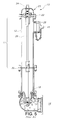
- the liquid or solid toxins in the barrel 12 can communicate with liquid in the water supply 16 in order to foul the water supply 16 , as shown in FIG. 5 , to the potential detriment of all those whose facilities are in communication with such water supply 16 .
Abstract
Description
Claims (22)
Priority Applications (2)
| Application Number | Priority Date | Filing Date | Title |
|---|---|---|---|
| US11/838,534 US7775231B2 (en) | 2002-12-04 | 2007-08-14 | Retrofitting a fire hydrant with a replacement hydrant body containing a secondary valve |
| PCT/US2008/073181 WO2009023780A1 (en) | 2007-08-14 | 2008-08-14 | Retrofitting a fire hydrant with a replacement hydrant body containing a secondary valve |
Applications Claiming Priority (4)
| Application Number | Priority Date | Filing Date | Title |
|---|---|---|---|
| US10/309,646 US6868860B2 (en) | 2002-12-04 | 2002-12-04 | Fire hydrant with second valve |
| US10/997,733 US7055544B2 (en) | 2002-12-04 | 2004-11-23 | Fire hydrant with a second valve |
| US11/372,947 US7428910B2 (en) | 2002-12-04 | 2006-03-09 | Breathable fire hydrant rod |
| US11/838,534 US7775231B2 (en) | 2002-12-04 | 2007-08-14 | Retrofitting a fire hydrant with a replacement hydrant body containing a secondary valve |
Related Parent Applications (1)
| Application Number | Title | Priority Date | Filing Date |
|---|---|---|---|
| US11/372,947 Continuation-In-Part US7428910B2 (en) | 2002-12-04 | 2006-03-09 | Breathable fire hydrant rod |
Publications (2)
| Publication Number | Publication Date |
|---|---|
| US20080135100A1 US20080135100A1 (en) | 2008-06-12 |
| US7775231B2 true US7775231B2 (en) | 2010-08-17 |
Family
ID=39863091
Family Applications (1)
| Application Number | Title | Priority Date | Filing Date |
|---|---|---|---|
| US11/838,534 Expired - Fee Related US7775231B2 (en) | 2002-12-04 | 2007-08-14 | Retrofitting a fire hydrant with a replacement hydrant body containing a secondary valve |
Country Status (2)
| Country | Link |
|---|---|
| US (1) | US7775231B2 (en) |
| WO (1) | WO2009023780A1 (en) |
Cited By (4)
| Publication number | Priority date | Publication date | Assignee | Title |
|---|---|---|---|---|
| US8302623B1 (en) | 2011-01-25 | 2012-11-06 | Nichols H Brunson | Anti-backflow insert for a fire hydrant outlet |
| US20130042924A1 (en) * | 2011-07-15 | 2013-02-21 | Albert Montague | Fire hydrant security integrated flow control/backflow preventer insert valve |
| USD854125S1 (en) | 2018-07-13 | 2019-07-16 | Mueller International, Llc | Modular hydrant |
| US10557252B2 (en) | 2016-11-28 | 2020-02-11 | 9309-0983 Québec Inc. | Fire hydrant valve and method for controlling a water flow in a fire hydrant conduit |
Families Citing this family (10)
| Publication number | Priority date | Publication date | Assignee | Title |
|---|---|---|---|---|
| US7775231B2 (en) | 2002-12-04 | 2010-08-17 | Davidson Hydrant Technologies, Inc. | Retrofitting a fire hydrant with a replacement hydrant body containing a secondary valve |
| US20070272300A1 (en) * | 2006-05-26 | 2007-11-29 | Thomas Dewey Davidson | Plated fire hydrant rod |
| US7575017B2 (en) * | 2006-10-06 | 2009-08-18 | Davidson Hydrant Technologies, Inc. | Wet barrel fire hydrant system with second valve |
| US20080245420A1 (en) * | 2007-04-09 | 2008-10-09 | Tom Randy Davidson | Nozzle Attachment for Fire Hydrant |
| CN102477758A (en) * | 2010-11-24 | 2012-05-30 | 苏州新格朗富机械科技有限公司 | Dustproof cap device of fire hydrant |
| CH706690A1 (en) * | 2012-06-28 | 2013-12-31 | Hinni Ag | Main valve for a fire hydrant. |
| CN107178122A (en) * | 2017-07-21 | 2017-09-19 | 宁夏如意科技时尚产业有限公司 | A kind of fire hydrant |
| US11156303B2 (en) | 2019-05-31 | 2021-10-26 | Mueller International, Llc | Break check valve for hydrant |
| US11204102B2 (en) | 2020-03-19 | 2021-12-21 | Mueller International, Llc | Watertight check valve |
| US11725746B2 (en) | 2021-06-07 | 2023-08-15 | Mueller International, Llc | Low water hammer break check valve |
Citations (70)
| Publication number | Priority date | Publication date | Assignee | Title |
|---|---|---|---|---|
| DE25159C (en) | königinmarienhütte, Aktien-Gesellschaft in Cainsdorf i. Sachsen | Device for the automatic emptying of hydrants by means of pistons | ||
| DE236645C (en) | ||||
| DE229997C (en) | ||||
| US154087A (en) | 1874-08-11 | Improvement in fire-plugs and hydrants | ||
| US726369A (en) | 1902-02-01 | 1903-04-28 | John J Sullivan | Valved appliance. |
| US1562223A (en) | 1924-03-08 | 1925-11-17 | Edgar M Moore | Hydrant |
| US1601993A (en) | 1925-06-22 | 1926-10-05 | Edward L Rick | Hydrant |
| FR735506A (en) | 1932-04-18 | 1932-11-10 | Pont A Mousson Fond | Device ensuring the non-freezing of fire hydrants, sprinklers, washing hydrants, fire hydrants and similar apparatus |
| DE639655C (en) | 1934-03-04 | 1936-12-10 | Polte Fa | Water post |
| CH191132A (en) | 1936-08-17 | 1937-05-31 | Ver Armaturen Gmbh | Water post. |
| US2083319A (en) | 1936-10-17 | 1937-06-08 | August H Daviet | Fire hydrant |
| US2109187A (en) | 1936-10-05 | 1938-02-22 | Joseph A Vogel | Frostproof hydrant |
| US2244993A (en) | 1939-10-25 | 1941-06-10 | Mike Hochler | Double gated safety fire hydrant |
| US2515770A (en) | 1947-05-17 | 1950-07-18 | Gronberg John Henric Paulus | Fire hydrant |
| US2580199A (en) | 1947-04-04 | 1951-12-25 | J A Zurn Mfg Company | Nonfreezing hydrant |
| US3017896A (en) | 1959-05-11 | 1962-01-23 | Frank C Papacek | Sanitary frostproof hydrant |
| US3035609A (en) | 1958-01-02 | 1962-05-22 | Phillips Petroleum Co | Fluid handling structure |
| US3158170A (en) | 1961-03-07 | 1964-11-24 | Howard A Tubbs | Yard hydrant |
| US3294109A (en) | 1964-01-20 | 1966-12-27 | Mueller Co | Sealing means for fire hydrant actuator |
| US3380471A (en) | 1965-08-24 | 1968-04-30 | Mueller Co | Wet-barrel fire hydrant |
| US3475978A (en) | 1968-11-18 | 1969-11-04 | Dresser Ind | Fire hydrant |
| US3566905A (en) | 1969-04-01 | 1971-03-02 | Woodford Mfg Co | Hydrant purging means |
| US3586019A (en) | 1968-12-18 | 1971-06-22 | Waterous Co | Fire hydrant |
| DE2237019A1 (en) | 1971-08-11 | 1973-02-22 | Walter Ing Boehm | HYDRANT |
| US3770000A (en) | 1968-12-23 | 1973-11-06 | Murdock Inc | Sanitary frostproof hydrant |
| US3858599A (en) * | 1973-10-16 | 1975-01-07 | Mark Controls Corp | Sanitary frostproof hydrant |
| US3939861A (en) | 1974-07-19 | 1976-02-24 | Thompson William J | Fire hydrant |
| US3952770A (en) | 1973-12-17 | 1976-04-27 | Botnick Irlin H | Non-freeze wall hydrant with vacuum breaker |
| US3961642A (en) | 1975-03-10 | 1976-06-08 | Waterous Company | Fire hydrant valve rod coupling |
| US3980097A (en) | 1975-07-29 | 1976-09-14 | Mueller Co. | Fire hydrant with drain valve and backflow preventer mechanism |
| US4022421A (en) | 1975-12-01 | 1977-05-10 | Carlin Jack M | Delayed release valve for a fire hydrant |
| US4139931A (en) | 1976-07-30 | 1979-02-20 | Waterous Company | Assembly method for fire hydrants |
| US4307746A (en) * | 1979-04-30 | 1981-12-29 | Rifat Sultan A | Frost-proof fire hydrant |
| US4393891A (en) | 1980-09-23 | 1983-07-19 | Ocean B.V. | Device for temporarily rinsing a water cock countersunk in the ground |
| US4440190A (en) | 1981-02-12 | 1984-04-03 | Pont-A-Mousson S.A. | Control mechanism for a fire hydrant |
| EP0113913A1 (en) | 1982-12-24 | 1984-07-25 | Bopp & Reuther Aktiengesellschaft | Underground or overground hydrant |
| US4475570A (en) | 1981-10-16 | 1984-10-09 | Prier Brass Manufacturing Co. | Anti-syphon freezeless water hydrant |
| US4602654A (en) | 1985-09-04 | 1986-07-29 | Hydra-Shield Manufacturing Co. | Coupling for fire hydrant-fire hose connection |
| US4791952A (en) | 1988-01-22 | 1988-12-20 | Halliburton Company | Hydrant and components thereof |
| US4813378A (en) | 1987-08-10 | 1989-03-21 | Lapp Alvin K | Animal watering fountain |
| US4909270A (en) | 1989-09-18 | 1990-03-20 | Arrowhead Brass Products, Inc. | Anti-siphon frost free faucet |
| CH675139A5 (en) | 1987-10-12 | 1990-08-31 | Von Roll Ag | Hydrant with frost protection device - with shut-off valve which ensures that stand-pipe is drained before cover can be replaced |
| US5029603A (en) | 1990-07-20 | 1991-07-09 | Watts Regulator Company | Anti-siphon frost-proof water hydrant |
| EP0463702A1 (en) | 1990-06-22 | 1992-01-02 | Rmi Holland B.V. | Fire hydrant with check valve |
| US5129416A (en) | 1990-07-20 | 1992-07-14 | Watts Regulator Company | Anti-siphon frost-proof water hydrant |
| US5549133A (en) | 1994-12-23 | 1996-08-27 | Sigelakis; George | Security device and system for preventing unauthorized access to and operation of fire hydrants |
| US5609179A (en) | 1995-09-25 | 1997-03-11 | Dawn Hartman | Automatic shut-off valve |
| US5622202A (en) | 1994-03-22 | 1997-04-22 | Etter; Mitchell K. | Tamper proof fire hydrant |
| FR2773373A1 (en) | 1998-01-07 | 1999-07-09 | Edmond Hilari | Shoe cleaner for path |
| DE19803901A1 (en) | 1998-02-02 | 1999-08-05 | Robert Messmer | Valve seat insert comprising parts firmly connected to one another |
| US6058957A (en) | 1997-09-08 | 2000-05-09 | Honigsbaum; Richard | Water saver fire hydrant |
| EP1010822A1 (en) | 1998-12-19 | 2000-06-21 | Heinz-Jürgen Pfitzner | Hydrant |
| EP1010821A1 (en) | 1998-12-19 | 2000-06-21 | Heinz-Jürgen Pfitzner | No-return valve for hydrants |
| US6150037A (en) | 1996-02-15 | 2000-11-21 | Toyo Kohan Co., Ltd | Cladding material |
| US6401745B1 (en) | 2001-04-09 | 2002-06-11 | Harold Eugene Corder | Fire hydrant automatic shut-off valve |
| US6488048B2 (en) | 1998-10-21 | 2002-12-03 | Hoerbiger Ventilwerke Gmbh | Explosion relief valve |
| WO2004051009A1 (en) | 2002-12-04 | 2004-06-17 | Davidson Hydrant Security Co., Inc. | Fire hydrant with second valve |
| US6769446B1 (en) | 2003-08-14 | 2004-08-03 | Wcm Industries, Inc. | Freeze protection device for wall hydrants/faucets |
| US20040154659A1 (en) | 2003-02-06 | 2004-08-12 | Lafalce Anthony P. | Backflow prevention system |
| WO2004072388A2 (en) | 2003-02-06 | 2004-08-26 | Lafalce Anthony P | Backflow prevention system |
| US20050067016A1 (en) | 2003-09-26 | 2005-03-31 | Michael David Wigzell | Air valve assembly for a fire hydrant |
| US20060201551A1 (en) | 2002-12-04 | 2006-09-14 | Davidson Hydrant Technologies, Inc. | Breathable fire hydrant rod |
| US20060207657A1 (en) | 2002-12-04 | 2006-09-21 | Davidson Hydrant Technologies, Inc. | Retrofitting a fire hydrant with secondary valve |
| US7128083B2 (en) | 2002-12-20 | 2006-10-31 | James Jones Company | Wet barrel fire hydrant flow preventer |
| US20070157972A1 (en) | 2006-01-12 | 2007-07-12 | Hendey Arthur A | One way check valve for a fire hydrant water meter |
| US20070272300A1 (en) | 2006-05-26 | 2007-11-29 | Thomas Dewey Davidson | Plated fire hydrant rod |
| WO2007146083A2 (en) | 2006-06-06 | 2007-12-21 | Albert Montague | Backflow preventer valve |
| US20080083458A1 (en) | 2006-10-06 | 2008-04-10 | Thomas Dewey Davidson | Wet barrel fire hydrant system with second valve |
| WO2008124750A1 (en) | 2007-04-09 | 2008-10-16 | Davidson Hydrant Technologies, Inc. | Nozzle attachment for fire hydrant |
| WO2009023780A1 (en) | 2007-08-14 | 2009-02-19 | Davidson Hydrant Technologies, Inc. | Retrofitting a fire hydrant with a replacement hydrant body containing a secondary valve |
Family Cites Families (1)
| Publication number | Priority date | Publication date | Assignee | Title |
|---|---|---|---|---|
| US3588019A (en) * | 1969-07-07 | 1971-06-28 | Anthony J Cozeck | Bracket for electrical boxes |
-
2007
- 2007-08-14 US US11/838,534 patent/US7775231B2/en not_active Expired - Fee Related
-
2008
- 2008-08-14 WO PCT/US2008/073181 patent/WO2009023780A1/en active Application Filing
Patent Citations (80)
| Publication number | Priority date | Publication date | Assignee | Title |
|---|---|---|---|---|
| DE25159C (en) | königinmarienhütte, Aktien-Gesellschaft in Cainsdorf i. Sachsen | Device for the automatic emptying of hydrants by means of pistons | ||
| DE236645C (en) | ||||
| DE229997C (en) | ||||
| US154087A (en) | 1874-08-11 | Improvement in fire-plugs and hydrants | ||
| US726369A (en) | 1902-02-01 | 1903-04-28 | John J Sullivan | Valved appliance. |
| US1562223A (en) | 1924-03-08 | 1925-11-17 | Edgar M Moore | Hydrant |
| US1601993A (en) | 1925-06-22 | 1926-10-05 | Edward L Rick | Hydrant |
| FR735506A (en) | 1932-04-18 | 1932-11-10 | Pont A Mousson Fond | Device ensuring the non-freezing of fire hydrants, sprinklers, washing hydrants, fire hydrants and similar apparatus |
| DE639655C (en) | 1934-03-04 | 1936-12-10 | Polte Fa | Water post |
| CH191132A (en) | 1936-08-17 | 1937-05-31 | Ver Armaturen Gmbh | Water post. |
| US2109187A (en) | 1936-10-05 | 1938-02-22 | Joseph A Vogel | Frostproof hydrant |
| US2083319A (en) | 1936-10-17 | 1937-06-08 | August H Daviet | Fire hydrant |
| US2244993A (en) | 1939-10-25 | 1941-06-10 | Mike Hochler | Double gated safety fire hydrant |
| US2580199A (en) | 1947-04-04 | 1951-12-25 | J A Zurn Mfg Company | Nonfreezing hydrant |
| US2515770A (en) | 1947-05-17 | 1950-07-18 | Gronberg John Henric Paulus | Fire hydrant |
| US3035609A (en) | 1958-01-02 | 1962-05-22 | Phillips Petroleum Co | Fluid handling structure |
| US3017896A (en) | 1959-05-11 | 1962-01-23 | Frank C Papacek | Sanitary frostproof hydrant |
| US3158170A (en) | 1961-03-07 | 1964-11-24 | Howard A Tubbs | Yard hydrant |
| US3294109A (en) | 1964-01-20 | 1966-12-27 | Mueller Co | Sealing means for fire hydrant actuator |
| US3380471A (en) | 1965-08-24 | 1968-04-30 | Mueller Co | Wet-barrel fire hydrant |
| US3475978A (en) | 1968-11-18 | 1969-11-04 | Dresser Ind | Fire hydrant |
| US3586019A (en) | 1968-12-18 | 1971-06-22 | Waterous Co | Fire hydrant |
| US3770000A (en) | 1968-12-23 | 1973-11-06 | Murdock Inc | Sanitary frostproof hydrant |
| US3566905A (en) | 1969-04-01 | 1971-03-02 | Woodford Mfg Co | Hydrant purging means |
| DE2237019A1 (en) | 1971-08-11 | 1973-02-22 | Walter Ing Boehm | HYDRANT |
| US3858599A (en) * | 1973-10-16 | 1975-01-07 | Mark Controls Corp | Sanitary frostproof hydrant |
| US3952770A (en) | 1973-12-17 | 1976-04-27 | Botnick Irlin H | Non-freeze wall hydrant with vacuum breaker |
| US3939861A (en) | 1974-07-19 | 1976-02-24 | Thompson William J | Fire hydrant |
| US3961642A (en) | 1975-03-10 | 1976-06-08 | Waterous Company | Fire hydrant valve rod coupling |
| US3980097A (en) | 1975-07-29 | 1976-09-14 | Mueller Co. | Fire hydrant with drain valve and backflow preventer mechanism |
| US4022421A (en) | 1975-12-01 | 1977-05-10 | Carlin Jack M | Delayed release valve for a fire hydrant |
| US4139931A (en) | 1976-07-30 | 1979-02-20 | Waterous Company | Assembly method for fire hydrants |
| US4307746A (en) * | 1979-04-30 | 1981-12-29 | Rifat Sultan A | Frost-proof fire hydrant |
| US4393891A (en) | 1980-09-23 | 1983-07-19 | Ocean B.V. | Device for temporarily rinsing a water cock countersunk in the ground |
| US4440190A (en) | 1981-02-12 | 1984-04-03 | Pont-A-Mousson S.A. | Control mechanism for a fire hydrant |
| US4475570A (en) | 1981-10-16 | 1984-10-09 | Prier Brass Manufacturing Co. | Anti-syphon freezeless water hydrant |
| EP0113913A1 (en) | 1982-12-24 | 1984-07-25 | Bopp & Reuther Aktiengesellschaft | Underground or overground hydrant |
| US4602654A (en) | 1985-09-04 | 1986-07-29 | Hydra-Shield Manufacturing Co. | Coupling for fire hydrant-fire hose connection |
| US4813378A (en) | 1987-08-10 | 1989-03-21 | Lapp Alvin K | Animal watering fountain |
| CH675139A5 (en) | 1987-10-12 | 1990-08-31 | Von Roll Ag | Hydrant with frost protection device - with shut-off valve which ensures that stand-pipe is drained before cover can be replaced |
| US4791952A (en) | 1988-01-22 | 1988-12-20 | Halliburton Company | Hydrant and components thereof |
| US4909270A (en) | 1989-09-18 | 1990-03-20 | Arrowhead Brass Products, Inc. | Anti-siphon frost free faucet |
| EP0463702A1 (en) | 1990-06-22 | 1992-01-02 | Rmi Holland B.V. | Fire hydrant with check valve |
| US5029603A (en) | 1990-07-20 | 1991-07-09 | Watts Regulator Company | Anti-siphon frost-proof water hydrant |
| US5129416A (en) | 1990-07-20 | 1992-07-14 | Watts Regulator Company | Anti-siphon frost-proof water hydrant |
| US5622202A (en) | 1994-03-22 | 1997-04-22 | Etter; Mitchell K. | Tamper proof fire hydrant |
| US5549133A (en) | 1994-12-23 | 1996-08-27 | Sigelakis; George | Security device and system for preventing unauthorized access to and operation of fire hydrants |
| US5609179A (en) | 1995-09-25 | 1997-03-11 | Dawn Hartman | Automatic shut-off valve |
| US6150037A (en) | 1996-02-15 | 2000-11-21 | Toyo Kohan Co., Ltd | Cladding material |
| US6058957A (en) | 1997-09-08 | 2000-05-09 | Honigsbaum; Richard | Water saver fire hydrant |
| FR2773373A1 (en) | 1998-01-07 | 1999-07-09 | Edmond Hilari | Shoe cleaner for path |
| DE19803901A1 (en) | 1998-02-02 | 1999-08-05 | Robert Messmer | Valve seat insert comprising parts firmly connected to one another |
| US6488048B2 (en) | 1998-10-21 | 2002-12-03 | Hoerbiger Ventilwerke Gmbh | Explosion relief valve |
| EP1010822A1 (en) | 1998-12-19 | 2000-06-21 | Heinz-Jürgen Pfitzner | Hydrant |
| EP1010821A1 (en) | 1998-12-19 | 2000-06-21 | Heinz-Jürgen Pfitzner | No-return valve for hydrants |
| US6401745B1 (en) | 2001-04-09 | 2002-06-11 | Harold Eugene Corder | Fire hydrant automatic shut-off valve |
| US6868860B2 (en) * | 2002-12-04 | 2005-03-22 | Davidson Hydrant Technologies, Inc. | Fire hydrant with second valve |
| US7428910B2 (en) | 2002-12-04 | 2008-09-30 | Davidson Hydrant Technologies, Inc. | Breathable fire hydrant rod |
| WO2004051009A1 (en) | 2002-12-04 | 2004-06-17 | Davidson Hydrant Security Co., Inc. | Fire hydrant with second valve |
| US7240688B2 (en) * | 2002-12-04 | 2007-07-10 | Davidson Hydrant Technologies, Inc. | Retrofitting a fire hydrant with secondary valve |
| US7174911B2 (en) | 2002-12-04 | 2007-02-13 | Davidson Hydrant Technologies, Inc. | Fire hydrant with second valve |
| US20060108002A1 (en) | 2002-12-04 | 2006-05-25 | Davidson Thomas D | Fire hydrant with second valve |
| US7055544B2 (en) | 2002-12-04 | 2006-06-06 | Davidson Hydrant Technologies, Inc. | Fire hydrant with a second valve |
| US20060201551A1 (en) | 2002-12-04 | 2006-09-14 | Davidson Hydrant Technologies, Inc. | Breathable fire hydrant rod |
| US20060207657A1 (en) | 2002-12-04 | 2006-09-21 | Davidson Hydrant Technologies, Inc. | Retrofitting a fire hydrant with secondary valve |
| US7128083B2 (en) | 2002-12-20 | 2006-10-31 | James Jones Company | Wet barrel fire hydrant flow preventer |
| US20080023072A1 (en) | 2002-12-20 | 2008-01-31 | James Jones Company | Wet barrel fire hydrant flow preventer |
| US6910495B2 (en) | 2003-02-06 | 2005-06-28 | Anthony P. Lafalce | Backflow prevention system |
| WO2004072388A2 (en) | 2003-02-06 | 2004-08-26 | Lafalce Anthony P | Backflow prevention system |
| US20040154659A1 (en) | 2003-02-06 | 2004-08-12 | Lafalce Anthony P. | Backflow prevention system |
| US6769446B1 (en) | 2003-08-14 | 2004-08-03 | Wcm Industries, Inc. | Freeze protection device for wall hydrants/faucets |
| US20050067016A1 (en) | 2003-09-26 | 2005-03-31 | Michael David Wigzell | Air valve assembly for a fire hydrant |
| US20070157972A1 (en) | 2006-01-12 | 2007-07-12 | Hendey Arthur A | One way check valve for a fire hydrant water meter |
| US20070272300A1 (en) | 2006-05-26 | 2007-11-29 | Thomas Dewey Davidson | Plated fire hydrant rod |
| WO2007146083A2 (en) | 2006-06-06 | 2007-12-21 | Albert Montague | Backflow preventer valve |
| US20080083458A1 (en) | 2006-10-06 | 2008-04-10 | Thomas Dewey Davidson | Wet barrel fire hydrant system with second valve |
| WO2008045785A1 (en) | 2006-10-06 | 2008-04-17 | Davidson Hydrant Technologies Inc. | Wet barrel fire hydrant system with second valve |
| US7575017B2 (en) * | 2006-10-06 | 2009-08-18 | Davidson Hydrant Technologies, Inc. | Wet barrel fire hydrant system with second valve |
| WO2008124750A1 (en) | 2007-04-09 | 2008-10-16 | Davidson Hydrant Technologies, Inc. | Nozzle attachment for fire hydrant |
| WO2009023780A1 (en) | 2007-08-14 | 2009-02-19 | Davidson Hydrant Technologies, Inc. | Retrofitting a fire hydrant with a replacement hydrant body containing a secondary valve |
Non-Patent Citations (11)
| Title |
|---|
| EP2078117 Office Action dated Sep. 14, 2009. |
| International Search Report and Written Opinion issued by the European Patent Office for PCT/US2007/063068 mailed Nov. 21, 2007. |
| International Search Report and Written Opinion issued by the European Patent Office for PCT/US2007/080572 mailed Feb. 18, 2008. |
| Mexican Patent Application No. PA/a/2005/006002 English Translations of Official Action dated Sep. 13, 2007. |
| PCT/US08/59715 International Search Report and Written Opinion dated Sep. 11, 2008. |
| PCT/US08/73181 International Search Report and Written Opinion dated Nov. 5, 2008. |
| PCT/US2003/37681 International Preliminary Examination Report mailed Jan. 17, 2005. |
| PCT/US2003/37681 International Search Report mailed May 4, 2004. |
| PCT/US2007/063064 International Search Report and Written Opinion mailed Jul. 10, 2007. |
| PCT/US2007/063068 Invitation to Pay and Partial International Search Report mailed Aug. 2, 2007. |
| PCT/US2008/059715 International Preliminary Report on Patentability dated Oct. 22, 2009. |
Cited By (5)
| Publication number | Priority date | Publication date | Assignee | Title |
|---|---|---|---|---|
| US8302623B1 (en) | 2011-01-25 | 2012-11-06 | Nichols H Brunson | Anti-backflow insert for a fire hydrant outlet |
| US20130042924A1 (en) * | 2011-07-15 | 2013-02-21 | Albert Montague | Fire hydrant security integrated flow control/backflow preventer insert valve |
| US8997777B2 (en) * | 2011-07-15 | 2015-04-07 | Albert Montague | Fire hydrant security integrated flow control/backflow preventer insert valve |
| US10557252B2 (en) | 2016-11-28 | 2020-02-11 | 9309-0983 Québec Inc. | Fire hydrant valve and method for controlling a water flow in a fire hydrant conduit |
| USD854125S1 (en) | 2018-07-13 | 2019-07-16 | Mueller International, Llc | Modular hydrant |
Also Published As
| Publication number | Publication date |
|---|---|
| US20080135100A1 (en) | 2008-06-12 |
| WO2009023780A1 (en) | 2009-02-19 |
Similar Documents
| Publication | Publication Date | Title |
|---|---|---|
| US7775231B2 (en) | Retrofitting a fire hydrant with a replacement hydrant body containing a secondary valve | |
| US7174911B2 (en) | Fire hydrant with second valve | |
| US7240688B2 (en) | Retrofitting a fire hydrant with secondary valve | |
| US7575017B2 (en) | Wet barrel fire hydrant system with second valve | |
| US9534359B2 (en) | Anchor valve for security | |
| US11788264B2 (en) | Automatic draining back flow prevention device | |
| US7686031B2 (en) | Hydrant shoe with backflow prevention assembly | |
| US3980097A (en) | Fire hydrant with drain valve and backflow preventer mechanism | |
| US20080245420A1 (en) | Nozzle Attachment for Fire Hydrant | |
| US20060016479A1 (en) | Backflow prevention valve | |
| EP2855987B1 (en) | Compact air stop valve for aircraft galley plumbing system | |
| EP2505889B1 (en) | Dual-direction in-tank magnetic safety valve | |
| US20090320933A1 (en) | Weeping System for Fire Hydrant Having a Protective Valve or Device | |
| US20060081293A1 (en) | Control valve for backwash prevention | |
| US5941274A (en) | Method and apparatus for securing a fire hydrant or other valve devices | |
| JP3007490U (en) | Backflow prevention type antifreeze water tap |
Legal Events
| Date | Code | Title | Description |
|---|---|---|---|
| AS | Assignment |
Owner name: DAVIDSON HYDRANT TECHNOLOGIES, GEORGIA Free format text: ASSIGNMENT OF ASSIGNORS INTEREST;ASSIGNOR:PHILLIPS, DAVID;REEL/FRAME:021049/0992 Effective date: 20050601 |
|
| AS | Assignment |
Owner name: DAVIDSON HYDRANT TECHNOLOGIES, INC., GEORGIA Free format text: ASSIGNMENT OF ASSIGNORS INTEREST;ASSIGNORS:DAVIDSON, TOM R., SR.;FERRARI, ANTHONY;WALDEN, DAVID MICHAEL;REEL/FRAME:021232/0586 Effective date: 20080411 |
|
| FEPP | Fee payment procedure |
Free format text: PAYOR NUMBER ASSIGNED (ORIGINAL EVENT CODE: ASPN); ENTITY STATUS OF PATENT OWNER: SMALL ENTITY |
|
| FEPP | Fee payment procedure |
Free format text: PETITION RELATED TO MAINTENANCE FEES FILED (ORIGINAL EVENT CODE: PMFP); ENTITY STATUS OF PATENT OWNER: SMALL ENTITY Free format text: PETITION RELATED TO MAINTENANCE FEES GRANTED (ORIGINAL EVENT CODE: PMFG); ENTITY STATUS OF PATENT OWNER: SMALL ENTITY |
|
| REMI | Maintenance fee reminder mailed | ||
| LAPS | Lapse for failure to pay maintenance fees | ||
| REIN | Reinstatement after maintenance fee payment confirmed | ||
| FP | Lapsed due to failure to pay maintenance fee |
Effective date: 20140817 |
|
| PRDP | Patent reinstated due to the acceptance of a late maintenance fee |
Effective date: 20141218 |
|
| FPAY | Fee payment |
Year of fee payment: 4 |
|
| FEPP | Fee payment procedure |
Free format text: MAINTENANCE FEE REMINDER MAILED (ORIGINAL EVENT CODE: REM.) |
|
| LAPS | Lapse for failure to pay maintenance fees |
Free format text: PATENT EXPIRED FOR FAILURE TO PAY MAINTENANCE FEES (ORIGINAL EVENT CODE: EXP.); ENTITY STATUS OF PATENT OWNER: SMALL ENTITY |
|
| STCH | Information on status: patent discontinuation |
Free format text: PATENT EXPIRED DUE TO NONPAYMENT OF MAINTENANCE FEES UNDER 37 CFR 1.362 |
|
| FP | Lapsed due to failure to pay maintenance fee |
Effective date: 20180817 |