EP1010821A1 - No-return valve for hydrants - Google Patents
No-return valve for hydrants Download PDFInfo
- Publication number
- EP1010821A1 EP1010821A1 EP98124283A EP98124283A EP1010821A1 EP 1010821 A1 EP1010821 A1 EP 1010821A1 EP 98124283 A EP98124283 A EP 98124283A EP 98124283 A EP98124283 A EP 98124283A EP 1010821 A1 EP1010821 A1 EP 1010821A1
- Authority
- EP
- European Patent Office
- Prior art keywords
- backflow preventer
- preventer according
- plate
- closing body
- perforated
- Prior art date
- Legal status (The legal status is an assumption and is not a legal conclusion. Google has not performed a legal analysis and makes no representation as to the accuracy of the status listed.)
- Withdrawn
Links
Images


Classifications
-
- E—FIXED CONSTRUCTIONS
- E03—WATER SUPPLY; SEWERAGE
- E03B—INSTALLATIONS OR METHODS FOR OBTAINING, COLLECTING, OR DISTRIBUTING WATER
- E03B9/00—Methods or installations for drawing-off water
- E03B9/02—Hydrants; Arrangements of valves therein; Keys for hydrants
- E03B9/16—Devices for retaining foreign matter, e.g. sand
Definitions
- the present invention relates to the urban and municipal water supply, in particular on the hydrants, such as tapping points for removal of water from public water networks serve.
- hydrants such as tapping points for removal of water from public water networks serve.
- Such hydrants mostly as underground hydrants trained and directly to the underground water pipe connected, serve primarily the fire brigade for water extraction; however, they can also be from private individuals be used by means of a standpipe.
- Usual hydrants of which the present invention is basically valves with a valve plate trained valve closing body, which by means of a Actuating spindle can be pressed onto its valve seat, the operating spindle in one at the top of a arranged as a sleeve tube extension tube Mother grabs and the valve plate at the bottom End of the sleeve tube is rigidly connected to this.
- the object of the present invention is to create a possibility to retrofit the existing hydrants that the danger of such sabotage attacks is largely minimized.
- Hydrants are of a common design and differ only by using non-return valves various types are retrofitted.
- the casing tube 1 of the hydrant is by means of one at the bottom End trained connecting flange 2 with the underground Water pipe connected.
- the actuating spindle 3 acts with one in the upper end the sleeve tube 8 formed spindle nut together.
- a valve closing body 6 attached, in the area of the casing tube has a residual water drain 7.
- the casing tube 1 has at the junction with the Connection sleeve 5 a flange with two on opposite Circumferential points trained flange ears and the Connection sleeve 5 itself has a corresponding flange 10. There are holes in the flange ears of both flanges executed, reach through the connecting screws.
- the check valves to be described are cartridge-like cylindrical inserts 11 in one place have flange plates 12 of their axial extension, whose outline with two opposite one another Flange ears and bores 13 of the shape of the flanges of Jacket tube 1 and connecting sleeve 5 corresponds.
- For retrofitting of an existing hydrant is therefore only the connecting sleeve 5 to dismantle and after placing one Backflow preventer insert 11 on the jacket pipe flange and the intermediate layer of seals and tightening the insert 11.
- the backflow preventer insert 11 of the first form of training 2 consists essentially of a cylindrical housing 15 with a perforated plate base 16. If below and in the claims of perforated sheet elements it is understood that this also as steel mesh or similar perforated flat Wall elements can be formed.
- the upper limit of the housing 15 consists of a the stability serving outer sheet metal ring 17 and one the inner area covering perforated sheet metal ceiling 18 the perforated sheet ceiling 18 is a dirt trap 37, that of a rubber sheet with two circular incisions exists, which is almost half a size extend. This makes two almost semi-circular Lobes formed which flow when the water flows bend upwards and release the flow. At rest prevent dirt from falling in the casing tube 1.
- the cylindrical housing 15 is in the lower third of it Height interrupted by the flange plate 12, which is with your flange ears outwards and inside of the housing forms a peripheral ring, which as Non-return valve check valve seat works.
- the plate-like closing body 20 of this check valve is connected to one through the perforated plate base 16 downwardly projecting shaft 21, which is in a guide sleeve 22 slides, the upper edge of which on the perforated plate base 16 is attached.
- the lower end of the shaft 21 emerges of the guide sleeve 22 and is suitable with a helical compression spring acting as a return spring 23 connected, the guide sleeve 22 coaxially surrounds and the upper end thereof on the perforated plate bottom 16 supports.
- the return spring 23 is in turn surrounded by a spring protection sleeve 24, the upper end of the perforated plate bottom 16 is attached and the lower end open is, so that their free annulus also as a flow space is available.
- a sealing ring 25 is arranged with which the closing plate 20 interacts.
- a perforated plate cylinder 26 is arranged coaxially of the sheet metal ring 17, in the lower area of the movement space of the locking plate 20 is. Above this range about half way up the perforated plate cylinder 26, is clear cross section through a stop and locking plate 27 closed, which gives access to the Locking plate prevented from above and that as a stroke limitation works for this.
- the mode of operation of the non-return valve described is that of a check valve. Is that on the connection sleeve 5 shot consumers and the actuating valve 6 opened, the water pressure overcomes in the network the force of the return spring 23 and lifts the Locking plate 20 from the seal 25. The water flows through the perforated plate cylinder, as indicated by arrows 26 below the stop and locking plate 27 from the inside to the outside, flows through the annular jacket space 19 between housing 15 and perforated plate cylinder 26 and occurs above the plate 27 from the outside in again the perforated plate cylinder 26 to finally through the To flow off perforated sheet metal ceiling 18.
- a cartridge-like backflow preventer insert 11 ' is the closing body 20' with one projecting upwards Shaft 21 'provided through a central opening the stop and locking plate 27 'protrudes and in a guide sleeve 22 'ends, the upper end of the perforated sheet ceiling 18 'is attached.
- the return spring 23 ' also a helical compression spring works here pressing directly on the closing body 21 '. It can be seen that the operation of this backflow preventer is the same as for the first Training variant described.
- valve closing body 6 '' a ball
- its weight makes a return spring unnecessary.
- the ball has one free movement between their seat on the ring seal 25 '' and the stop and locking plate 27 ''.
- the position of the closing ball 6 '' when the operating valve is open is shown in dashed lines.
- stop and locking plate 27 '' is not of a perforated plate cylinder is held, but by one A plurality of round bars evenly distributed around the circumference 38, which form a round rod cage. These cage bars are at the level of the stop and locking plate 27 '', i.e. about half their length, divided and the Halves of the bar are under restraint of the stop and Locking plate screwed together.
- a cartridge-like Backflow preventer insert 11 '' 'according to FIGS. 8, 9 the perforated plate base 16 '' 'frustoconical and the closing body 20 '' 'has the shape of a double cone, the one cooperating with the sealing ring 25 '' ' Area of the cone converging downwards with a Soft seal coating 30 is provided.
- the return spring 23 '' ' is a helical tension spring, between the guide sleeve 22 '' 'and the Spring protection sleeve 24 '' 'is seated and its upper end appropriate way near the bottom of the Double cone closing body 20 '' 'and its lower end at a suitable fixed location on the perforated plate floor 16 '' 'or the lower end of the guide sleeve 22' '' or Spring protection sleeve 24 '' 'is attached.
- the blocking and Stop plate 27 '' ' has a the upper cone of the Double cone closing body 20 '' 'adapted shape. The Operation of this backflow preventer differs does not differ in principle from those previously described.
- the fifth form of training a cartridge-like Check valve insert 11 '' '' has a check valve construction with two semicircular, against a spring action opening in the direction of flow Flaps 33.
- the central flange plate 12 '' '' has a diametrical bearing web 34 extending through its central opening which the two check valves 33 are mounted.
- the Edging of the semicircular openings that result is provided with appropriately installed seals 25 '' '', the with the edges of the swing check valves in the closed position of the same interact.
- the landing stage 34 carries a torsion spring 35, each leg one of the check valves in the sense of closing acted upon.
- the clear cross section of the perforated plate cylinder 26 '' '' covering plate 27 '' '' only has the function here a lock against unauthorized interference the check valve mechanism.
Abstract
Description
Die vorliegende Erfindung bezieht sich auf die städtische und kommunale Wasserversorgung, und zwar insbesondere auf die Hydranten, wie sie als Zapfstellen zur Entnahme von Wasser aus den öffentlichen Wassernetzen dienen. Solche Hydranten, meist als Unterflur-Hydranten ausgebildet und unmittelbar an die unterirdische Wasserleitung angeschlossen, dienen vor allem der Feuerwehr zur Wasserentnahme; sie können jedoch auch von Privaten mittels eines Standrohres benutzt werden.The present invention relates to the urban and municipal water supply, in particular on the hydrants, such as tapping points for removal of water from public water networks serve. Such hydrants, mostly as underground hydrants trained and directly to the underground water pipe connected, serve primarily the fire brigade for water extraction; however, they can also be from private individuals be used by means of a standpipe.
Übliche Hydranten, von denen die vorliegende Erfindung ausgeht, sind im Grunde Ventile mit einem als Ventilteller ausgebildeten Ventilschließkörper, der mittels einer Betätigungsspindel auf seinen Ventilsitz andrückbar ist, wobei die Betätigungsspindel in eine am oberen Ende eines als Hülsrohr bezeichneten Verlängerungsrohres angeordnete Mutter greift und der Ventilteller am unteren Ende des Hülsrohres starr mit diesem verbunden ist.Usual hydrants, of which the present invention is basically valves with a valve plate trained valve closing body, which by means of a Actuating spindle can be pressed onto its valve seat, the operating spindle in one at the top of a arranged as a sleeve tube extension tube Mother grabs and the valve plate at the bottom End of the sleeve tube is rigidly connected to this.
Diese Hydranten bieten keine Sicherheit gegen Sabotage. Sie sind jedermann zugänglich und kriminelle Elemente könnten zu Zwecken der Erpressung oder aus anderen Gründen Krankheitserreger oder Gift oder dergleichen in das städtische Wassernetz einleiten, wozu lediglich ein leicht verfügbares Standrohr sowie eine Pumpe oder eine andere Überdruckquelle erforderlich wäre, mittels deren die gefährlichen Substanzen unter einem den Leitungsdruck übertreffenden Druck eingeführt werden könnten.These hydrants offer no security against sabotage. They are accessible to everyone and criminal elements could be for extortion or other reasons Pathogen or poison or the like in that initiate urban water network, for which only a easily available standpipe as well as a pump or a other source of excess pressure would be required, by means of which the dangerous substances under a line pressure surpassing pressure could be introduced.
Aufgabe der vorliegenden Erfindung ist die Schaffung einer Möglichkeit, die vorhandenen Hydranten so nachzurüsten, dass die Gefahr solcher Sabotageanschläge weitgehend minimiert ist.The object of the present invention is to create a possibility to retrofit the existing hydrants that the danger of such sabotage attacks is largely minimized.
Die Lösung der gestellten Aufgabe gelingt durch die in den Patentansprüchen angegebenen Merkmale. Durch den vorgeschlagenen Rückflußverhinderer wird auf einfache Weise ein Rückschlagventil in den Weg des ausströmenden Wassers gelegt, wobei die einzelnen Ausgestaltungen so konzipiert sind, dass die Rückflußverhinderung nur mit größerem Aufwand überwunden werden könnte und somit eine wesentlich größere Sicherheit gewährleistet ist.The task is solved by the in the features specified in the claims. By the proposed backflow preventer is simple Way a check valve in the way of the outflowing Water laid, the individual configurations so are designed to prevent backflow only with greater effort could be overcome and thus a much greater security is guaranteed.
Die Erfindung wird nachfolgend durch die Beschreibung von fünf Ausführungsbeispielen anhand der beigegebenen Zeichnungen weiter erläutert. Es zeigt:
- Fig. 1
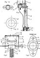
- den Schnitt durch einen Hydranten mit einem Rückflußverhinderer einer ersten Ausführungsform;
- Fig. 1A
- die Draufsicht auf die Anschlußmuffe des Hydranten;
- Fig. 2
- schematisch den Rückflußverhinderer der ersten Ausführungsform im Schnitt;
- Fig. 3
- den Schnitt A-A gemäß Fig. 2;
- Fig. 4
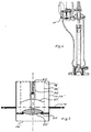
- den Schnitt durch einen Hydranten mit einem Rückflußverhinderer einer zweiten Ausführungsform ;
- Fig. 5
- schematisch den Rückflußverhinderer der zweiten Ausführungsform im Schnitt;
- Fig. 6
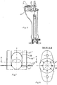
- den Schnitt durch einen Hydranten mit einem Rückflußverhinderer einer dritten Ausführungsform;
- Fig. 7
- schematisch den Rückflußverhinderer der dritten Ausführungsform im Schnitt;
- Fig. 8
- den Schnitt durch einen Hydranten mit einem Rückflußverhinderer einer vierten Ausführungsform;
- Fig. 9
- schematisch den Rückflußverhinderer der vierten Ausführungsform im Schnitt;
- Fig. 10
- den Schnitt durch einen Hydranten mit einem Rückflußverhinderer einer fünften Ausführungsform;
- Fig. 11
- schematisch den Rückflußverhinderer der fünften Ausführungsform im Schnitt;
- Fig. 12
- den Schnitt A-A in Fig. 11;
- Fig. 13
- eine Draufsicht auf einen Schmutzfänger.
- Fig. 1
- the section through a hydrant with a backflow preventer of a first embodiment;
- Fig. 1A
- the top view of the connecting sleeve of the hydrant;
- Fig. 2
- schematically the backflow preventer of the first embodiment in section;
- Fig. 3
- the section AA of FIG. 2;
- Fig. 4
- the section through a hydrant with a backflow preventer of a second embodiment;
- Fig. 5
- schematically the backflow preventer of the second embodiment in section;
- Fig. 6
- the section through a hydrant with a backflow preventer of a third embodiment;
- Fig. 7
- schematically the backflow preventer of the third embodiment in section;
- Fig. 8
- the section through a hydrant with a backflow preventer of a fourth embodiment;
- Fig. 9
- schematically shows the backflow preventer of the fourth embodiment in section;
- Fig. 10
- the section through a hydrant with a backflow preventer of a fifth embodiment;
- Fig. 11
- schematically the backflow preventer of the fifth embodiment in section;
- Fig. 12
- the section AA in Fig. 11;
- Fig. 13
- a top view of a strainer.
Die im Zusammenhang mit der vorliegenden Erfindung gezeigten Hydranten sind von üblicher Bauart und unterscheiden sich lediglich dadurch, dass sie mit Rückflußverhinderern verschiedener Bauart nachgerüstet sind.Those shown in connection with the present invention Hydrants are of a common design and differ only by using non-return valves various types are retrofitted.
Das Mantelrohr 1 des Hydranten ist mittels eines am unteren
Ende ausgebildeten Anschlußflanschs 2 mit der unterirdischen
Wasserleitung verbunden. Am oberen Ende
befindet sich das Lager für die Betätigungsspindel 3 mit
ihrem Bedienungsvierkant 4 und neben diesem die Anschlußmuffe
5 für eine Schlauchkupplung oder ein Standrohr.The
Die Betätigungsspindel 3 wirkt mit einer im oberen Ende
des Hülsrohres 8 ausgebildeten Spindelmutter zusammen.
Am unteren Ende des Hülsrohres 8 ist ein ventilschließkörper
6 befestigt, in dessen Bereich das Mantelrohr
einen Restwasserabfluß 7 aufweist.The
Das Mantelrohr 1 hat an der Verbindungsstelle mit der
Anschlußmuffe 5 einen Flansch mit zwei an gegenüberliegenden
Umfangsstellen ausgebildeten Flanschohren und die
Anschlußmuffe 5 hat selbst einen entsprechenden Flansch
10. In den Flanschohren beider Flansche sind Bohrungen
ausgeführt, durch die verbindungsschrauben greifen.The
Die zu beschreibenden Rückflußverhinderer sind kartuschenartige
zylindrische Einsätze 11, die an einer Stelle
ihrer axialen Erstreckung Flanschplatten 12 aufweisen,
deren Umriß mit zwei einander gegenüberliegenden
Flanschohren und Bohrungen 13 der Form der Flansche von
Mantelrohr 1 und Anschlußmuffe 5 entspricht. Zur Umrüstung
eines vorhandenen Hydranten ist somit nur die Anschlußmuffe
5 zu demontieren und nach Aufsetzen eines
Rückflußverhinderer-Einsatzes 11 auf den Mantelrohrflansch
und Zwischenlage von Dichtungen wieder zu montieren
und unter Einspannung des Einsatzes 11 festzuziehen.The check valves to be described are cartridge-like
cylindrical inserts 11 in one place
have
Der Rückflußverhinderer-Einsatz 11 der ersten Ausbildungsform
gemäß Fig. 2 besteht im wesentlichen aus einem
zylindrischen Gehäuse 15 mit einem Lochblechboden 16.
Wenn nachfolgend und in den Patentansprüchen von Lochblechelementen
die Rede ist, versteht es sich, dass diese
auch als Stahlgeflecht oder ähnliche perforierte flächige
Wandelemente ausgebildet sein können.The backflow preventer insert 11 of the first form of
Die obere Begrenzung des Gehäuses 15 besteht aus einem
der Stabilität dienenden äußeren Blechring 17 und einer
dessen Innenbereich überdeckenden Lochblechdecke 18. Auf
der Lochblechdecke 18 liegt ein Schmutzfänger 37 auf,
der aus einer Gummiplatte mit zwei Kreisbogeneinschnitten
besteht, welche sich über fast einen halben Umfang
erstrecken. Dadurch sind zwei nahezu halbkreisförmige
Lappen gebildet, welche sich beim Strömen des Wassers
nach oben wegbiegen und den Durchfluß freigeben. Im Ruhezustand
verhindern sie ein Hineinfallen von Schmutz in
das Mantelrohr 1.The upper limit of the
Das zylindrische Gehäuse 15 ist im unteren Drittel seiner
Höhe unterbrochen von der Flanschplatte 12, die sich
mit Ihren Flanschohren nach außen fortsetzt und im Inneren
des Gehäuses einen peripheren Ring bildet, der als
Ventilsitz des Rückschlagventils des Rückflußverhinderers
wirkt.The
Der tellerartige Schließkörper 20 dieses Rückschlagventils
ist verbunden mit einem durch den Lochblechboden 16
nach unten ragenden Schaft 21, der in einer Führungshülse
22 gleitet, deren oberer Rand am Lochblechboden 16
befestigt ist. Das untere Ende des Schafts 21 tritt aus
der Führungshülse 22 hervor und ist auf geeignete Weise
mit einer als Rückholfeder 23 wirkenden Schraubenwendel-Druckfeder
verbunden, die die Führungshülse 22 koaxial
umgibt und deren oberes Ende sich am Lochblechboden 16
abstützt. Die Rückholfeder 23 ihrerseits ist umgeben von
einer Federschutzhülse 24, deren oberes Ende am Lochblechboden
16 befestigt ist und deren unteres Ende offen
ist, sodass ihr freier Ringraum auch als Strömungsraum
zur Verfügung steht.The plate-
Am Rand der zentralen Öffnung der Flanschplatte 12 ist
ein Dichtungsring 25 angeordnet, mit dem der Schließteller
20 zusammenwirkt.At the edge of the central opening of the flange plate 12
a sealing
Im Gehäuseinneren ist zwischen der Flanschplatte 12 und
dem Außenrand der Lochblechdecke 18 bzw. dem Innenrand
des Blechrings 17 koaxial ein Lochblechzylinder 26 angeordnet,
in dessen unterem Bereich der Bewegungsraum
des Schließtellers 20 liegt. Oberhalb dieses Bereichs,
etwa auf halber Höhe des Lochblechzylinders 26, ist dessen
lichter Querschnitt durch eine Anschlag- und Sperrplatte
27 verschlossen, welche einen Zugriff auf den
Schließteller von oben verhindert und die als Hubbegrenzung
für diesen wirkt.Inside the housing is between the
Die Wirkungsweise des beschriebenen Rückflußverhinderers
ist die eines Rückschlagventils. Ist der an der Anschlußmuffe
5 angeschossene Verbraucher sowie das Betätigungsventil
6 geöffnet, so überwindet der Wasserdruck
im Netz die Kraft der Rückholfeder 23 und hebt den
Schließteller 20 von der Dichtung 25 ab. Das Wasser
durchströmt, wie durch Pfeile angedeutet, den Lochblechzylinder
26 unterhalb der Anschlag- und Sperrplatte 27
von innen nach außen, durchströmt den Ringmantelraum 19
zwischen Gehäuse 15 und Lochblechzylinder 26 und tritt
oberhalb der Platte 27 wieder von außen nach innen in
den Lochblechzylinder 26 ein, um schließlich durch die
Lochblechdecke 18 abzuströmen.The mode of operation of the non-return valve described
is that of a check valve. Is that on the
In der in Fig. 4, 5 gezeigten zweiten Ausbildungsform eines kartuschenartigen Rückflußverhinderer-Einsatzes 11' ist der Schließkörper 20' mit einem nach oben ragenden Schaft 21' versehen, der durch eine zentrale Öffnung der Anschlag- und Sperrplatte 27' ragt und in einer Führungshülse 22' endet, deren oberes Ende an der Lochblechdecke 18' befestigt ist. Die Rückholfeder 23', ebenfalls eine Schraubenwendel-Druckfeder, wirkt hier unmittelbar drückend auf den Schließkörperschaft 21'. Es ist zu sehen, dass die Wirkungsweise dieses Rückflußverhinderers die gleiche ist wie bezüglich der ersten Ausbildungsvariante beschrieben.In the second embodiment shown in FIGS. 4, 5 a cartridge-like backflow preventer insert 11 'is the closing body 20' with one projecting upwards Shaft 21 'provided through a central opening the stop and locking plate 27 'protrudes and in a guide sleeve 22 'ends, the upper end of the perforated sheet ceiling 18 'is attached. The return spring 23 ', also a helical compression spring works here pressing directly on the closing body 21 '. It can be seen that the operation of this backflow preventer is the same as for the first Training variant described.
In der dritten Ausbildungsform eines kartuschenartigen Rückflußverhinderer-Einsatzes 11'' gemäß Fig. 6, 7 ist der Ventilschließkörper 6'' eine Kugel, deren Gewicht eine Rückholfeder entbehrlich macht. Die Kugel hat einen freien Bewegungsweg zwischen ihrem Sitz auf der Ringdichtung 25'' und der Anschlag- und Sperrplatte 27''. Die Position der Schließkugel 6'' bei geöffnetem Betätigungsventil ist gestrichelt eingezeichnet.In the third form of training a cartridge-like Backflow preventer insert 11 '' according to FIGS. 6, 7 the valve closing body 6 '' a ball, its weight makes a return spring unnecessary. The ball has one free movement between their seat on the ring seal 25 '' and the stop and locking plate 27 ''. The position of the closing ball 6 '' when the operating valve is open is shown in dashed lines.
Ein weiterer Unterschied dieser Ausbildungsform liegt
darin, dass die Anschlag- und Sperrplatte 27'' nicht von
einem Lochblechzylinder gehalten ist, sondern von einer
Mehrzahl von gleichmäßig auf dem Umfang verteilten Rundstäben
38, die einen runden Stabkäfig bilden. Diese Käfigstäbe
sind auf der Höhe der Anschlag- und Sperrplatte
27'', also etwa auf ihrer halben Länge, geteilt und die
Stabhälften sind unter Einspannung der Anschlag- und
Sperrplatte miteinander verschraubt.Another difference of this form of training lies
in that the stop and locking plate 27 '' is not of
a perforated plate cylinder is held, but by one
A plurality of round bars evenly distributed around the
In der vierten Ausführungsform eines kartuschenartigen
Rückflußverhinderer-Einsatzes 11''' gemäß Fig. 8, 9 ist
der Lochblechboden 16''' kegelstumpfförmig gestaltet und
der Schließkörper 20''' hat die Form eines Doppelkegels,
wobei der mit dem Dichtungsring 25''' zusammenwirkende
Bereich des nach unten konvergierenden Kegels mit einer
Weichdichtungsbeschichtung 30 versehen ist.In the fourth embodiment, a cartridge-like
Backflow preventer insert 11 '' 'according to FIGS. 8, 9
the perforated plate base 16 '' 'frustoconical and
the closing body 20 '' 'has the shape of a double cone,
the one cooperating with the sealing ring 25 '' '
Area of the cone converging downwards with a
Die Rückholfeder 23''' ist hier eine Schraubenwendel-Zugfeder, die zwischen der Führungshülse 22''' und der Federschutzhülse 24''' sitzt und deren oberes Ende auf geeignete Weise in der Nähe des unteren Randes des Doppelkegel-Schließkörpers 20''' und deren unteres Ende an einer geeigneten ortsfesten Stelle am Lochblechboden 16''' oder dem unteren Ende von Führungshülse 22''' oder Federschutzhülse 24''' befestigt ist. Die Sperr- und Anschlagplatte 27''' hat eine dem oberen Kegel des Doppelkegel-Schließkörpers 20''' angepaßte Form. Die Funktionsweise dieses Rückflußverhinderers unterscheidet sich nicht prinzipiell von den zuvor beschriebenen.The return spring 23 '' 'is a helical tension spring, between the guide sleeve 22 '' 'and the Spring protection sleeve 24 '' 'is seated and its upper end appropriate way near the bottom of the Double cone closing body 20 '' 'and its lower end at a suitable fixed location on the perforated plate floor 16 '' 'or the lower end of the guide sleeve 22' '' or Spring protection sleeve 24 '' 'is attached. The blocking and Stop plate 27 '' 'has a the upper cone of the Double cone closing body 20 '' 'adapted shape. The Operation of this backflow preventer differs does not differ in principle from those previously described.
Die fünfte Ausbildungsform eines kartuschenartigen Rückflußverhinderer-Einsatzes 11'''' besitzt eine Rückschlagventilkonstruktion mit zwei halbkreisförmigen, entgegen einer Federwirkung in Strömungsrichtung öffnenden Klappen 33.The fifth form of training a cartridge-like Check valve insert 11 '' '' has a check valve construction with two semicircular, against a spring action opening in the direction of flow Flaps 33.
Die zentrale Flanschplatte 12'''' hat einen diametral
über ihre zentrale Öffnung verlaufenden Lagersteg 34, an
dem die beiden Rückschlagklappen 33 gelagert sind. Die
Berandung der dadurch entstehenden Halbkreisöffnungen
ist mit entsprechend verlegten Dichtungen 25'''' versehen,
die mit den Rändern der Rückschlagklappen in der
geschlossenen Lage derselben zusammenwirken. Der Lagersteg
34 trägt eine Torsionsfeder 35, deren jeder Schenkel
eine der Rückschlagklappen im Sinne des Schließens
beaufschlagt. Die oberhalb dieser Konstruktion angeordnete,
den lichten Querschnitt des Lochblechzylinders
26'''' überdeckende Platte 27'''' hat hier nur die Funktion
einer Sperre gegenüber unbefugter Einwirkung auf
den Mechanismus des Rückschlagventils.The central flange plate 12 '' '' has a
Von der Oberseite der Rückschlagklappen 33 ragen Abstandshalter
36 auf, die die geöffnete Endstellung der
Rückschlagklappen definieren. Es ist zu sehen, dass diese
Ausbildung in ähnlicher Weise wirkt wie die zuvor
beschriebenen Ausbildungen. Spacers protrude from the top of the
- 11
- MantelrohrCasing pipe
- 22nd
- AnschlußflanschConnecting flange
- 33rd
- BetätigungsspindelOperating spindle
- 44th
- BedienungsvierkantOperating square
- 55
- AnschlußmuffeConnection sleeve
- 66
- VentilschließkörperValve closing body
- 77
- RestwasserabflußResidual water runoff
- 88th
- HülsrohrSleeve tube
- 1010th
- MuffenflanschSocket flange
- 1111
- Einsatzcommitment
- 1212th
- FlanschplatteFlange plate
- 1313
- Bohrungdrilling
- 1515
- Gehäusecasing
- 1616
- LochblechbodenPerforated plate bottom
- 1717th
- BlechringSheet metal ring
- 1818th
- LochblechdeckePerforated sheet ceiling
- 1919th
- RingmantelraumAnnular space
- 2020th
- Schließkörper, -TellerClosing body, plate
- 2121
- Schaftshaft
- 2222
- FührungshülseGuide sleeve
- 2323
- RückholfederReturn spring
- 2424th
- FederschutzhülseSpring protection sleeve
- 2525th
- DichtungsringSealing ring
- 2626
- LochblechzylinderPerforated plate cylinder
- 2727
- Anschlag- und SperrplatteStop and locking plate
- 3030th
- WeichdichtungsbeschichtungSoft seal coating
- 3333
- Klappeflap
- 3434
- LagerstegFootbridge
- 3535
- TorsionsfederTorsion spring
- 3636
- AbstandshalterSpacers
- 3737
- SchmutzfängerMud flaps
- 3838
- Zweigeteilte KäfigstäbeTwo-part cage bars
Claims (13)
Priority Applications (1)
| Application Number | Priority Date | Filing Date | Title |
|---|---|---|---|
| EP98124283A EP1010821A1 (en) | 1998-12-19 | 1998-12-19 | No-return valve for hydrants |
Applications Claiming Priority (1)
| Application Number | Priority Date | Filing Date | Title |
|---|---|---|---|
| EP98124283A EP1010821A1 (en) | 1998-12-19 | 1998-12-19 | No-return valve for hydrants |
Publications (1)
| Publication Number | Publication Date |
|---|---|
| EP1010821A1 true EP1010821A1 (en) | 2000-06-21 |
Family
ID=8233195
Family Applications (1)
| Application Number | Title | Priority Date | Filing Date |
|---|---|---|---|
| EP98124283A Withdrawn EP1010821A1 (en) | 1998-12-19 | 1998-12-19 | No-return valve for hydrants |
Country Status (1)
| Country | Link |
|---|---|
| EP (1) | EP1010821A1 (en) |
Cited By (10)
| Publication number | Priority date | Publication date | Assignee | Title |
|---|---|---|---|---|
| WO2004051009A1 (en) * | 2002-12-04 | 2004-06-17 | Davidson Hydrant Security Co., Inc. | Fire hydrant with second valve |
| US7240688B2 (en) | 2002-12-04 | 2007-07-10 | Davidson Hydrant Technologies, Inc. | Retrofitting a fire hydrant with secondary valve |
| US7428910B2 (en) | 2002-12-04 | 2008-09-30 | Davidson Hydrant Technologies, Inc. | Breathable fire hydrant rod |
| US7559338B2 (en) | 2005-08-04 | 2009-07-14 | Mueller International, Inc. | Keyless fire hydrant protection system |
| US7575017B2 (en) | 2006-10-06 | 2009-08-18 | Davidson Hydrant Technologies, Inc. | Wet barrel fire hydrant system with second valve |
| DE102008010574A1 (en) | 2008-02-22 | 2009-09-03 | Hawle Armaturen Gmbh | Water connection system for use with safety system for fire hydrant, has fire hydrant connection element formed as fire hydrant lower part for connection of fire hydrant to water supply line |
| US7686031B2 (en) | 2006-06-21 | 2010-03-30 | Mueller International, Inc. | Hydrant shoe with backflow prevention assembly |
| US7775231B2 (en) | 2002-12-04 | 2010-08-17 | Davidson Hydrant Technologies, Inc. | Retrofitting a fire hydrant with a replacement hydrant body containing a secondary valve |
| FR2946369A1 (en) * | 2009-06-08 | 2010-12-10 | Veolia Eau Cie Generale Des Eaux | FIRE TERMINAL AND METHOD OF SECURING A FIRE FIGHTER. |
| EP3399112A1 (en) * | 2017-05-02 | 2018-11-07 | Hinni AG | Hydrant with back flow preventer in the upper part |
Citations (4)
| Publication number | Priority date | Publication date | Assignee | Title |
|---|---|---|---|---|
| US2605781A (en) * | 1946-09-23 | 1952-08-05 | J A Zurn Mfg Company | Hydrant |
| DD204279A1 (en) * | 1982-04-08 | 1983-11-23 | Harald Barby | COMBINED REVERSE FLOW PREVENTION AND VENTILATION DEVICE IN UNDERFLURHYDRANTS |
| FR2548544A1 (en) * | 1983-07-07 | 1985-01-11 | T J Clapets | Hydrant with non-return valve |
| US5129416A (en) * | 1990-07-20 | 1992-07-14 | Watts Regulator Company | Anti-siphon frost-proof water hydrant |
-
1998
- 1998-12-19 EP EP98124283A patent/EP1010821A1/en not_active Withdrawn
Patent Citations (4)
| Publication number | Priority date | Publication date | Assignee | Title |
|---|---|---|---|---|
| US2605781A (en) * | 1946-09-23 | 1952-08-05 | J A Zurn Mfg Company | Hydrant |
| DD204279A1 (en) * | 1982-04-08 | 1983-11-23 | Harald Barby | COMBINED REVERSE FLOW PREVENTION AND VENTILATION DEVICE IN UNDERFLURHYDRANTS |
| FR2548544A1 (en) * | 1983-07-07 | 1985-01-11 | T J Clapets | Hydrant with non-return valve |
| US5129416A (en) * | 1990-07-20 | 1992-07-14 | Watts Regulator Company | Anti-siphon frost-proof water hydrant |
Cited By (14)
| Publication number | Priority date | Publication date | Assignee | Title |
|---|---|---|---|---|
| US7775231B2 (en) | 2002-12-04 | 2010-08-17 | Davidson Hydrant Technologies, Inc. | Retrofitting a fire hydrant with a replacement hydrant body containing a secondary valve |
| WO2004051009A1 (en) * | 2002-12-04 | 2004-06-17 | Davidson Hydrant Security Co., Inc. | Fire hydrant with second valve |
| US7174911B2 (en) | 2002-12-04 | 2007-02-13 | Davidson Hydrant Technologies, Inc. | Fire hydrant with second valve |
| US7240688B2 (en) | 2002-12-04 | 2007-07-10 | Davidson Hydrant Technologies, Inc. | Retrofitting a fire hydrant with secondary valve |
| US7428910B2 (en) | 2002-12-04 | 2008-09-30 | Davidson Hydrant Technologies, Inc. | Breathable fire hydrant rod |
| US7055544B2 (en) | 2002-12-04 | 2006-06-06 | Davidson Hydrant Technologies, Inc. | Fire hydrant with a second valve |
| US7559338B2 (en) | 2005-08-04 | 2009-07-14 | Mueller International, Inc. | Keyless fire hydrant protection system |
| US7686031B2 (en) | 2006-06-21 | 2010-03-30 | Mueller International, Inc. | Hydrant shoe with backflow prevention assembly |
| US7575017B2 (en) | 2006-10-06 | 2009-08-18 | Davidson Hydrant Technologies, Inc. | Wet barrel fire hydrant system with second valve |
| DE102008010574A1 (en) | 2008-02-22 | 2009-09-03 | Hawle Armaturen Gmbh | Water connection system for use with safety system for fire hydrant, has fire hydrant connection element formed as fire hydrant lower part for connection of fire hydrant to water supply line |
| FR2946369A1 (en) * | 2009-06-08 | 2010-12-10 | Veolia Eau Cie Generale Des Eaux | FIRE TERMINAL AND METHOD OF SECURING A FIRE FIGHTER. |
| WO2010146283A1 (en) * | 2009-06-08 | 2010-12-23 | Veolia Eau - Compagnie Generale Des Eaux | Fire hydrant and method for securing a fire hydrant |
| EP3399112A1 (en) * | 2017-05-02 | 2018-11-07 | Hinni AG | Hydrant with back flow preventer in the upper part |
| CH713755A1 (en) * | 2017-05-02 | 2018-11-15 | Hinni Ag | Hydrant with backflow preventer in the upper part. |
Similar Documents
| Publication | Publication Date | Title |
|---|---|---|
| DE2005592A1 (en) | Shut-off element with pressure compensation device | |
| EP1010821A1 (en) | No-return valve for hydrants | |
| DE10028655B4 (en) | Pipe connection and such a pipe connection having height-adjustable hydrant | |
| EP0999311A1 (en) | Manhole cover for dust tight closure of manholes, in particular for wells | |
| DE1976609U (en) | BRIDGE-LIKE DRILL HOLE INSERT. | |
| WO2017118583A1 (en) | Valve armature for the filling of a sanitary cistern and sanitary cistern having a valve armature of this type | |
| DE3435778A1 (en) | Hydrant, in particular underground hydrant | |
| EP1010822A1 (en) | Hydrant | |
| DE102006006339B3 (en) | Backflow preventer for underground hydrant, has closing unit with ventilating valve for controlling flow path of water from discharge chamber to internal chamber and for closing path, when high pressure is developed in internal chamber | |
| DE19933453C2 (en) | Backflow preventer for underground hydrants | |
| DE202019104886U1 (en) | hydrant | |
| DE112009000468T5 (en) | Removable barrier | |
| EP3399112B1 (en) | Hydrant with back flow preventer in the upper part | |
| DE19546102C2 (en) | Arrangement for preventing the entry of vermin from a downpipe into toilet bowls | |
| DE202006004541U1 (en) | Street cap for installation in road or site has housing and cover which closes housing at upper end whereby gripping and stretching mechanism are provided between housing and cover for bracing and for engaging cover with housing | |
| EP1010824A1 (en) | Hydrant with ball valve | |
| DE202005019900U1 (en) | Street level access cover to sub-surface utility shaft has concrete-filled detent holding locking bolts | |
| DE102007060624B4 (en) | hydrant | |
| DE202005007628U1 (en) | Frost-proof pillar valve | |
| DE3031520A1 (en) | Underfloor water hydrant - has second valve sealing set for float pressed by spring pressure rod | |
| DE19715010B4 (en) | Hydraulic gripper with pressure relief valve | |
| DE10240906B4 (en) | Manhole for sewerage | |
| WO2020069992A1 (en) | Anti-backflow device, hose coupling for a hydrant and hydrant | |
| AT354363B (en) | LOCKING DEVICE FOR WELL LID, LOCK LID, LOCK REST AND THE LIKE | |
| DE202009000974U1 (en) | Street cap with latching on the bolt |
Legal Events
| Date | Code | Title | Description |
|---|---|---|---|
| PUAI | Public reference made under article 153(3) epc to a published international application that has entered the european phase |
Free format text: ORIGINAL CODE: 0009012 |
|
| AK | Designated contracting states |
Kind code of ref document: A1 Designated state(s): AT BE CH CY DE DK ES FI FR GB GR IE IT LI LU MC NL PT SE |
|
| AX | Request for extension of the european patent |
Free format text: AL;LT;LV;MK;RO;SI |
|
| AKX | Designation fees paid | ||
| STAA | Information on the status of an ep patent application or granted ep patent |
Free format text: STATUS: THE APPLICATION IS DEEMED TO BE WITHDRAWN |
|
| 18D | Application deemed to be withdrawn |
Effective date: 20001222 |