US7757715B2 - Accumulator and method of manufacturing flow damper - Google Patents
Accumulator and method of manufacturing flow damper Download PDFInfo
- Publication number
- US7757715B2 US7757715B2 US11/564,034 US56403406A US7757715B2 US 7757715 B2 US7757715 B2 US 7757715B2 US 56403406 A US56403406 A US 56403406A US 7757715 B2 US7757715 B2 US 7757715B2
- Authority
- US
- United States
- Prior art keywords
- flow pipe
- vortex chamber
- small flow
- junction
- large flow
- Prior art date
- Legal status (The legal status is an assumption and is not a legal conclusion. Google has not performed a legal analysis and makes no representation as to the accuracy of the status listed.)
- Active, expires
Links
- 238000004519 manufacturing process Methods 0.000 title description 6
- 230000002093 peripheral effect Effects 0.000 claims abstract description 54
- 238000000034 method Methods 0.000 claims description 4
- XLYOFNOQVPJJNP-UHFFFAOYSA-N water Substances O XLYOFNOQVPJJNP-UHFFFAOYSA-N 0.000 description 48
- 238000002347 injection Methods 0.000 description 13
- 239000007924 injection Substances 0.000 description 13
- 239000002826 coolant Substances 0.000 description 11
- 238000001816 cooling Methods 0.000 description 11
- 238000004401 flow injection analysis Methods 0.000 description 7
- IJGRMHOSHXDMSA-UHFFFAOYSA-N Atomic nitrogen Chemical compound N#N IJGRMHOSHXDMSA-UHFFFAOYSA-N 0.000 description 2
- 229910001873 dinitrogen Inorganic materials 0.000 description 2
- 230000000694 effects Effects 0.000 description 2
- 239000007789 gas Substances 0.000 description 2
- 238000013461 design Methods 0.000 description 1
- 238000011161 development Methods 0.000 description 1
- 238000002474 experimental method Methods 0.000 description 1
- 238000012986 modification Methods 0.000 description 1
- 230000004048 modification Effects 0.000 description 1
Images


Classifications
-
- G—PHYSICS
- G21—NUCLEAR PHYSICS; NUCLEAR ENGINEERING
- G21C—NUCLEAR REACTORS
- G21C15/00—Cooling arrangements within the pressure vessel containing the core; Selection of specific coolants
- G21C15/18—Emergency cooling arrangements; Removing shut-down heat
-
- F—MECHANICAL ENGINEERING; LIGHTING; HEATING; WEAPONS; BLASTING
- F15—FLUID-PRESSURE ACTUATORS; HYDRAULICS OR PNEUMATICS IN GENERAL
- F15B—SYSTEMS ACTING BY MEANS OF FLUIDS IN GENERAL; FLUID-PRESSURE ACTUATORS, e.g. SERVOMOTORS; DETAILS OF FLUID-PRESSURE SYSTEMS, NOT OTHERWISE PROVIDED FOR
- F15B1/00—Installations or systems with accumulators; Supply reservoir or sump assemblies
- F15B1/26—Supply reservoir or sump assemblies
-
- F—MECHANICAL ENGINEERING; LIGHTING; HEATING; WEAPONS; BLASTING
- F15—FLUID-PRESSURE ACTUATORS; HYDRAULICS OR PNEUMATICS IN GENERAL
- F15D—FLUID DYNAMICS, i.e. METHODS OR MEANS FOR INFLUENCING THE FLOW OF GASES OR LIQUIDS
- F15D1/00—Influencing flow of fluids
- F15D1/0015—Whirl chambers, e.g. vortex valves
-
- Y—GENERAL TAGGING OF NEW TECHNOLOGICAL DEVELOPMENTS; GENERAL TAGGING OF CROSS-SECTIONAL TECHNOLOGIES SPANNING OVER SEVERAL SECTIONS OF THE IPC; TECHNICAL SUBJECTS COVERED BY FORMER USPC CROSS-REFERENCE ART COLLECTIONS [XRACs] AND DIGESTS
- Y02—TECHNOLOGIES OR APPLICATIONS FOR MITIGATION OR ADAPTATION AGAINST CLIMATE CHANGE
- Y02E—REDUCTION OF GREENHOUSE GAS [GHG] EMISSIONS, RELATED TO ENERGY GENERATION, TRANSMISSION OR DISTRIBUTION
- Y02E30/00—Energy generation of nuclear origin
- Y02E30/30—Nuclear fission reactors
-
- Y—GENERAL TAGGING OF NEW TECHNOLOGICAL DEVELOPMENTS; GENERAL TAGGING OF CROSS-SECTIONAL TECHNOLOGIES SPANNING OVER SEVERAL SECTIONS OF THE IPC; TECHNICAL SUBJECTS COVERED BY FORMER USPC CROSS-REFERENCE ART COLLECTIONS [XRACs] AND DIGESTS
- Y10—TECHNICAL SUBJECTS COVERED BY FORMER USPC
- Y10T—TECHNICAL SUBJECTS COVERED BY FORMER US CLASSIFICATION
- Y10T137/00—Fluid handling
- Y10T137/206—Flow affected by fluid contact, energy field or coanda effect [e.g., pure fluid device or system]
- Y10T137/2087—Means to cause rotational flow of fluid [e.g., vortex generator]
- Y10T137/2098—Vortex generator as control for system
-
- Y—GENERAL TAGGING OF NEW TECHNOLOGICAL DEVELOPMENTS; GENERAL TAGGING OF CROSS-SECTIONAL TECHNOLOGIES SPANNING OVER SEVERAL SECTIONS OF THE IPC; TECHNICAL SUBJECTS COVERED BY FORMER USPC CROSS-REFERENCE ART COLLECTIONS [XRACs] AND DIGESTS
- Y10—TECHNICAL SUBJECTS COVERED BY FORMER USPC
- Y10T—TECHNICAL SUBJECTS COVERED BY FORMER US CLASSIFICATION
- Y10T137/00—Fluid handling
- Y10T137/206—Flow affected by fluid contact, energy field or coanda effect [e.g., pure fluid device or system]
- Y10T137/2087—Means to cause rotational flow of fluid [e.g., vortex generator]
- Y10T137/2109—By tangential input to axial output [e.g., vortex amplifier]
- Y10T137/2115—With means to vary input or output of device
-
- Y—GENERAL TAGGING OF NEW TECHNOLOGICAL DEVELOPMENTS; GENERAL TAGGING OF CROSS-SECTIONAL TECHNOLOGIES SPANNING OVER SEVERAL SECTIONS OF THE IPC; TECHNICAL SUBJECTS COVERED BY FORMER USPC CROSS-REFERENCE ART COLLECTIONS [XRACs] AND DIGESTS
- Y10—TECHNICAL SUBJECTS COVERED BY FORMER USPC
- Y10T—TECHNICAL SUBJECTS COVERED BY FORMER US CLASSIFICATION
- Y10T29/00—Metal working
- Y10T29/49—Method of mechanical manufacture
Definitions
- the present invention relates to an accumulator incorporating a flow damper which is capable of statically switching flow rates from large to small, and to a method of manufacturing the flow damper.
- the present invention is useful when applied to an emergency injection system for a reactor in a pressurized water reactor (PWR) power plant, for example.
- PWR pressurized water reactor
- An emergency core cooling system is installed in the PWR power plant.
- the emergency core cooling system includes an accumulator and so forth on the assumption that the PWR might cause a loss of primary coolant accident.
- Water (coolant) is stored in the accumulator, and the water stored therein is pressurized by a pressurizing gas (nitrogen gas) which is filled in an upper part in the accumulator.
- a flow damper is provided in the accumulator.
- the flow damper can switch a water injection flow rate in a reactor from a large flow to a small flow statically (without moving any part thereof).
- the flow damper includes a vortex chamber, a large flow pipe, a small flow pipe, an outlet pipe and the like, and is disposed at the bottom in the accumulator (see FIG. 1 ).
- a tip end of the outlet pipe is connected to a low temperature pipeline of a reactor primary coolant loop with a check valve interposed in between. The check valve is used for avoiding a back flow from a rector primary cooling system to the accumulator.
- the amount of the coolant in a reactor vessel may be reduced, and thereby a reactor core may become exposed.
- a pressure of the primary cooling system drops below a pressure in the accumulator, the water stored in the accumulator is injected from the primary cooling system pipeline into the reactor vessel through the check valve, and thereby refloods the reactor core.
- the reactor vessel is refilled quickly by injecting water at a large flow rate at an initial stage thereof. Then, it is necessary to switch the water injection flow rate from the large flow to a small flow at a later stage when the reactor core is reflooded, because excessively injected water may spill out of the crack. In order to ensure this water injection flow rate switching operation, a reliable flow damper without a moving part is used for the accumulator.
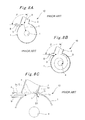
- FIGS. 8A to 8C horizontal sectional views
- a flow damper 10 has a structure in which a large flow pipe 2 and a small flow pipe 3 are connected to a peripheral portion (a circumferential portion) of a cylindrical vortex chamber 1 , while an outlet 4 is formed in the center of the vortex chamber 1 .
- the large flow pipe 2 and the small flow pipe 3 extend in mutually different directions from the outlet 4 .
- the small flow pipe 3 extends in the left direction along a tangential direction to the peripheral portion (the circumferential portion) of the vortex chamber 1 .
- the large flow pipe 2 extends in the right direction while forming a predetermined angle ⁇ with the small flow pipe 3 .
- an inlet of the small flow pipe 3 is located at the same level as the vortex chamber 1 .
- the large flow pipe 2 is connected to a standpipe which extends upward.
- An inlet of this standpipe is located higher than the vortex chamber 1 and the inlet of the small flow pipe 3 .
- an outlet pipe is connected to the outlet 4 of the vortex chamber 1 .
- the water in the accumulator flows into the vortex chamber 1 from both of the large flow pipe 2 and the small flow pipe 3 as indicated with arrows A and B in FIG. 8A .
- the injected water (a jet) from the large flow pipe 2 collides with the injected water (a jet) from the small flow pipe 3 , and angular momenta of the jets are offset.
- the water flows directly toward the outlet 4 as indicated with an arrow C in FIG. 8A .
- no vortex is formed in the vortex chamber at this time. Accordingly, a flow resistance is reduced at this time, and thus a large amount of water flows out of the outlet 4 and is injected into the reactor vessel.
- the accumulator currently in development is the advanced accumulator which is capable of switching flows from large to small statically and securely by including the flow damper 10 .
- the flow damper 10 of this advanced accumulator is required to define a proportion between the large flow and the small flow as high as possible in order to achieve a reasonable tank volume. For this reason, it is essential not to form a vortex in the vortex chamber by surely offsetting the angular momenta between the jet from the large flow pipe 2 and the jet from the small flow pipe 3 at the time of the large flow injection. Meanwhile, it is necessary to generate a high flow resistance by forming a strong vortex in the vortex chamber 1 when switching from the large flow to the small flow.
- the strong vortex is formed in the vortex chamber 1 by connecting the small flow pipe 3 along the tangential direction to the peripheral portion (the circumferential portion) of the vortex chamber 1 .
- the water flow (a free jet) blown out of the small flow pipe 3 into the vortex chamber 1 not only includes a direct flow along the tangential direction (see a dashed line E) but also includes a flow which spreads out of the extension line E of an inner surface 3 a, at the side of the large flow pipe 2 , of the small flow pipe 3 as indicated with a dashed line F (a proportion of spread caused by this free flow is approximately equal to 1/10).
- a junction 6 of the large flow pipe 2 (an inner surface 2 a ) and the vortex chamber 1 (an inner surface 1 a ) is located either on the extension line E or inside the extension line E.
- part of the jet from the small flow pipe 3 collides with the inner surface 2 a of the large flow pipe 2 as indicated with an arrow G, and flows into the vortex chamber 2 while bypassing the junction 6 of the large flow pipe 2 and the vortex chamber 1 .
- the part of the jet is detached from the inner surface 1 a of the vortex chamber 1 , and flows in an inclined flow direction toward the center of the vortex chamber 1 as compared to the aforementioned tangential direction. Due to an influence of this flow, the overall flow direction of the jet from the small flow pipe 3 is inclined toward the center of the vortex chamber 1 as compared to the tangential direction (as indicated with an arrow B 1 ). Accordingly, the vortex formed in the vortex chamber 1 is weakened by reduction of the angular momentum of the jet.
- an object of the present invention is to provide an accumulator including a flow damper, which is capable of forming a strong vortex in a vortex chamber at the time of a small flow injection and thereby obtaining a high flow resistance.
- an accumulator is an accumulator provided with a flow damper inside, the flow damper including a cylindrical vortex chamber, a small flow pipe connected to a peripheral portion of the vortex chamber along a tangential direction thereto, a large flow pipe connected to the peripheral portion while forming a predetermined angle with the small flow pipe, and an outlet pipe connected to an outlet formed at a central part of the vortex chamber.
- the accumulator is characterized in that a first junction of the large flow pipe and the vortex chamber of the flow damper is located outside an extension line of an inner surface, at the side of the large flow pipe, of the small flow pipe.
- an accumulator according to a second aspect of the present invention in the case of the accumulator of the first aspect, is characterized in that: a straight line is drawn from the first junction in a free-jet-spread proportion relative to the extension line of the inner surface, at the side of the large flow pipe, of the small flow pipe, the extension line drawn from a second junction of the large flow pipe and the small flow pipe; a first intersecting point of the straight line and an inner surface, at the opposite side of the small flow pipe, of the large flow pipe is obtained; a tangent is drawn from the first intersecting point to an inner peripheral surface of the vortex chamber to obtain a second intersecting point of the tangent and the inner peripheral surface of the vortex chamber; a flat surface portion including a line linking the first intersecting point with the second intersecting point is used as an extended surface portion of the inner peripheral surface of the vortex chamber; and a junction of the extended surface portion and the inner surface, at the opposite side of the small flow pipe, of the large flow pipe is the first junction
- a method of manufacturing a flow damper is a method of manufacturing a flow damper including a cylindrical vortex chamber, a small flow pipe connected to a peripheral portion of the vortex chamber along a tangential direction thereto, a large flow pipe connected to the peripheral portion while forming a predetermined angle with the small flow pipe, and an outlet pipe connected to an outlet formed at a central part of the vortex chamber, the method characterized by including the steps of: drawing an extension line of an inner surface, at the side of the large flow pipe, of the small flow pipe from a second junction of the large flow pipe and the small flow pipe; drawing a straight line from a first junction in a free-jet-spread proportion relative to the extension line; obtaining a first intersecting point of the straight line and an inner surface, at the opposite side of the small flow pipe, of the large flow pipe; drawing a tangent from the first intersecting point to an inner peripheral surface of the vortex chamber to obtain a second intersecting point of the tangent
- the accumulator of the first aspect of the present invention is characterized in that the first junction of the large flow pipe and the vortex chamber of the flow damper is located outside the extension line of the inner surface, at the side of the large flow pipe, of the small flow pipe. Accordingly, a spreading portion of a free jet from the small flow pipe flows along the inner peripheral surface of the vortex chamber at the time of a small flow injection without being detached from the inner peripheral surface of the vortex chamber. Hence it is possible to form a strong vortex in the vortex chamber and to obtain a high flow resistance.
- the accumulator of the second aspect of the present invention is characterized in that: a straight line is drawn from the first junction in a free-jet-spread proportion relative to the extension line of the inner surface, at the side of the large flow pipe, of the small flow pipe, the extension line drawn from a second junction of the large flow pipe and the small flow pipe; a first intersecting point of the straight line and an inner surface, at the opposite side of the small flow pipe, of the large flow pipe is obtained; a tangent is drawn from the first intersecting point to an inner peripheral surface of the vortex chamber to obtain a second intersecting point of the tangent and the inner peripheral surface of the vortex chamber; a flat surface portion including a line linking the first intersecting point with the second intersecting point is used as an extended surface portion of the inner peripheral surface of the vortex chamber; and a junction of the extended surface portion and the inner surface, at the opposite side of the small flow pipe, of the large flow pipe is the first junction of the large flow pipe and the vortex chamber.
- the method of manufacturing a flow damper of the third aspect of the present invention is characterized in that: a straight line is drawn from the first junction in a free-jet-spread proportion relative to the extension line of the inner surface, at the side of the large flow pipe, of the small flow pipe, the extension line drawn from a second junction of the large flow pipe and the small flow pipe; a first intersecting point of the straight line and an inner surface, at the opposite side of the small flow pipe, of the large flow pipe is obtained; a tangent is drawn from the first intersecting point to an inner peripheral surface of the vortex chamber to obtain a second intersecting point of the tangent and the inner peripheral surface of the vortex chamber; a flat surface portion including a line linking the first intersecting point with the second intersecting point is used as an extended surface portion of the inner peripheral surface of the vortex chamber; and a junction of the extended surface portion and the inner surface, at the opposite side of the small flow pipe, of the large flow pipe is the first junction of the large flow pipe and the vortex chamber.
- the spreading portion of the free jet from the small flow pipe flows more securely along the inner peripheral surface (the extended surface portion) of the vortex chamber at the time of a small flow injection without being detached from the inner peripheral surface (the extended surface portion) of the vortex chamber.
- FIG. 1 is a cross-sectional view of an accumulator according to an embodiment of the present invention
- FIG. 2 is an enlarged cross-sectional view extracting and showing a flow damper included in the accumulator
- FIG. 3 is a plan view of the flow damper
- FIG. 4 is a cross-sectional view taken along, and indicated by, the H-H arrow line in FIG. 2 ;
- FIG. 5A is a cross-sectional view taken along, and indicated by, the I-I line in FIG. 4
- FIG. 5B is a cross-sectional view taken along, and indicated by, the J-J line in FIG. 4 ;
- FIG. 6 is an enlarged cross-sectional view of a substantial part in FIG. 4 ;
- FIGS. 7A and 7B are views for explaining water injection flow switching by use of the flow damper.
- FIGS. 8A to 8C are views for explaining water injection flow switching by use of a conventional flow damper.
- An accumulator 21 shown in FIG. 1 is an apparatus constituting part of an emergency core cooling system, which is installed in a pressurized water reactor (PWR) power plant on the assumption that a loss of primary coolant accident might occur in the PWR power plant.
- PWR pressurized water reactor
- water (a coolant) 22 is stored in the accumulator 21 , and the water 22 stored therein is pressurized by a pressurizing gas (nitrogen gas) 23 which is filled in an upper part in the accumulator 21 .
- a flow damper 24 which can switch a water injection flow rate in a reactor from a large flow to a small flow statically, is provided in the accumulator 21 .
- the flow damper 24 includes a vortex chamber 25 , a large flow pipe 26 , a small flow pipe 27 , an outlet pipe 28 and the like, and is disposed at the bottom in the accumulator 21 .
- a tip end of the outlet pipe 28 is connected to a low temperature pipeline of a reactor primary coolant loop with a check valve interposed in between. The check valve is used for avoiding a back flow from a rector primary cooling system to the accumulator 21 .
- the flow damper 24 has a structure in which the large flow pipe 26 and the small flow pipe 27 are connected to a peripheral portion (a. circumferential portion) of the cylindrical vortex chamber 25 , while an outlet 29 is formed in the center of an upper surface 25 b of the vortex chamber 25 .
- the outlet 29 may be provided in the center of a lower surface 25 c of the vortex chamber 25 .
- the large flow pipe 26 and the small flow pipe 27 extend in mutually different directions from the outlet 29 .
- the small flow pipe 27 extends in a direction (which is the left direction in the drawings) along a tangential direction to the peripheral portion (the circumferential portion) of the vortex chamber 25 .
- the large flow pipe 26 extends in another direction (which is the right direction in the drawings) while forming a predetermined angle ⁇ (in a range from 90° ⁇ 180°; such as 95°, 100° or 110°) with the small flow pipe 27 .
- Cross sections of flow passages of the large flow pipe 26 and the small flow pipe 27 are formed into rectangular shapes.
- the large flow pipe 26 (a horizontal portion 26 a ) has a parallel pair of inner surfaces (vertical surfaces) 26 d and 26 e which face each other in the horizontal direction, and a parallel pair of inner surfaces (horizontal surfaces) 26 f and 26 g which face each other in the vertical direction.
- the small flow pipe 27 has a parallel pair of inner surfaces (vertical surfaces) 27 b and 27 c which face each other in the horizontal direction, and a parallel pair of inner surfaces (horizontal surfaces) 27 d and 27 e which face each other in the vertical direction.
- the heights of the flow-passage cross sections of the large flow pipe 26 and the small flow pipe 27 are the same as the height of an inner peripheral surface 25 a of the vortex chamber 25 .
- the widths of the flow-passage cross sections of the large flow pipe 26 are greater than the widths of the flow-passage cross sections of the small flow pipe 27 (the widths of the inner surfaces 27 d and 27 e ).
- an inlet 27 a of the small flow pipe 27 is located at the same height as that of the inner peripheral surface 25 a of the vortex chamber 25 .
- the large flow pipe 26 includes a standpipe 26 b connected to the horizontal portion 26 a, and an inlet 26 c thereof is located higher than the vortex chamber 25 and the inlet 27 a of the small flow pipe 27 .
- a water level 22 a of the stored water 22 is usually located higher than this inlet 26 c of the large flow pipe 26 .
- the outlet pipe 28 is connected to the outlet 29 of the vortex chamber 25 .
- Anti-vortex plates 30 and 31 are respectively provided to the inlets 26 c and 27 a of the large flow pipe 26 and the small flow pipe 27 .
- the flow damper 24 of this embodiment has a structure of a wall facing the small flow pipe, in which a junction 32 of the large flow pipe 26 (the inner surface 26 d located opposite to the small flow pipe 27 ) and the vortex chamber 25 (an extended surface portion 25 a - 1 , at the opposite side of the small flow pipe 27 ,of the inner peripheral surface 25 a ) is located outside (upward in FIG. 6 ) an extension line (a virtual line) K of the inner surface 27 b, at the side of the large flow pipe 26 , of the small flow pipe 27 .
- the virtual line K is the extension line of the inner surface 27 b of the small flow pipe 27 , i.e., a straight line extending from a junction 33 (an intersecting point P 3 which is a point at the junction 33 ) of the inner surface 27 b of the small flow pipe 27 and the inner surface 26 e, at the side of the small flow pipe 27 , of the large flow pipe 26 along an axial direction (i.e., the tangential direction) of the small flow pipe 27 .
- a virtual line L is a straight line representing a free-jet-spread of the water injected from the small flow pipe 27 into the vortex chamber 25 .
- a free-jet-spread proportion (an inclination of the straight line L relative to the straight line K) is set at 1/10.
- the free-jet-spread proportion the above-mentioned generally known value may be used, or a free-jet-spread proportion may be set up in accordance with an experiment as appropriate.
- a virtual line M is a curve (an arc) along the circular shape of the inner peripheral surface 25 a of the vortex chamber 25 .
- concrete design procedures for obtaining the junction 32 of inner surface 26 d of the large flow pipe 26 and the inner peripheral surface 25 a of the vortex chamber 25 (i.e. an intersecting point P 1 at the junction 32 ) are as follows.
- the straight line L is drawn from the junction 33 (the intersecting point P 3 ) in the free-jet-spread proportion relative to the extension line K drawn from the junction 33 (the intersecting point P 3 ), and the intersecting point P 1 of this straight line L and the inner surface 26 d of the large flow pipe 26 is obtained.
- a tangent (not shown) is drawn from this intersecting point P 1 toward the inner peripheral surface 25 a of the vortex chamber 25 , and an intersecting point P 2 of this tangent and the inner peripheral surface 25 a is obtained.
- the flat surface portion 25 a - 1 including a line which links the intersecting point P 1 with the intersecting point P 2 (i.e.
- the tangent is used as the extended surface portion of the inner peripheral surface 25 a (here, a line linking the center ⁇ of the vortex chamber 25 with the intersecting point P 2 and the flat surface portion (the extended surface portion) 25 a - 1 form a right angle).
- the inner surface 26 d of the large flow pipe 26 is connected to the flat surface portion (the extended surface portion) 25 a - 1 of the inner peripheral surface 25 a of the vortex chamber 25 .
- this junction 32 (the intersecting point P 1 ) is located (on the straight line L) outside the extension line K.
- the accumulator 21 having the above-described configuration exerts the following operation and effects.
- the water 22 in the accumulator 21 flows into the vortex chamber 25 from both of the large flow pipe 26 and the small flow pipe 27 as indicated with arrows A and B in FIG. 7A .
- the injected water (a jet) from the large flow pipe 26 collides with the injected water (a jet) from the small flow pipe 27 , and angular momenta of the jets are offset.
- the water 22 flows directly toward the outlet 29 as indicated with an arrow C in FIG. 7A .
- no vortex is formed in the vortex chamber 25 at this time. Accordingly, a flow resistance is reduced at this time, and a large amount of water flows out of the outlet 29 and is injected into the reactor vessel.
- the accumulator 21 of this embodiment is characterized in that the junction 32 of the large flow pipe 26 (the inner surface 26 d ) and the vortex chamber 25 (the extended surface portion 25 a - 1 of the inner surface 25 a ) of the flow damper 24 is located outside the extension line of the inner surface 27 b, at the side of the large flow pipe 26 , of the small flow pipe 27 . Accordingly, the free-jet-spreading portion from the small flow pipe 27 flows along the inner peripheral surface 25 a of the vortex chamber 25 at the time of a small flow injection without being detached from the inner peripheral surface 25 a of the vortex chamber 25 . Hence it is possible to form a strong vortex in the vortex chamber 25 , and to obtain a high flow resistance.
- the flow damper 24 of this accumulator 21 is characterized in that: the straight line L is drawn from the junction 33 (the third intersecting point P 3 ) in the free-jet-spread proportion relative to the extension line K of the inner surface 27 b, at the side of the large flow pipe 26 , of the small flow pipe 27 drawn from the junction 33 (the third intersecting point P 3 ) of the small flow pipe 27 and the large flow pipe 26 ; the first intersecting point P 1 of this straight line L and the inner surface 26 d, at the opposite side of the small flow pipe 27 , of the large flow pipe 26 is obtained; the tangent is drawn from this first intersecting point P 1 to the inner peripheral surface 25 a of the vortex chamber 25 to obtain the second intersecting point P 2 of the tangent and the inner peripheral surface 25 a of the vortex chamber 25 ; the flat surface portion 25 a - 1 including the line (the tangent) linking the first intersecting point P 1 with the second intersecting point P 2 is used as the extended surface portion of the inner peripheral
- the free-jet-spreading portion from the small flow pipe 27 flows more securely along the inner peripheral surface 25 a (the extended surface portion 25 a - 1 ) of the vortex chamber 25 at the time of a small flow injection without being detached from the inner peripheral surface 25 a (the extended surface portion 25 a - 1 ) of the vortex chamber 25 , as indicated with an arrow N in FIG. 6 .
Landscapes
- Engineering & Computer Science (AREA)
- Physics & Mathematics (AREA)
- General Engineering & Computer Science (AREA)
- Plasma & Fusion (AREA)
- High Energy & Nuclear Physics (AREA)
- Fluid Mechanics (AREA)
- Mechanical Engineering (AREA)
- Pipe Accessories (AREA)
- Lift Valve (AREA)
Priority Applications (6)
| Application Number | Priority Date | Filing Date | Title |
|---|---|---|---|
| US11/564,034 US7757715B2 (en) | 2006-11-28 | 2006-11-28 | Accumulator and method of manufacturing flow damper |
| PCT/JP2007/072066 WO2008065888A1 (fr) | 2006-11-28 | 2007-11-14 | Procédé de fabrication de réservoir d'accumulation d'eau et de régulateur de débit |
| KR1020097010387A KR101025469B1 (ko) | 2006-11-28 | 2007-11-14 | 축압 주수 탱크 및 플로우 댐퍼의 제조 방법 |
| EP07831796.3A EP2088602B1 (en) | 2006-11-28 | 2007-11-14 | Manufacturing method for accumulator water injection tank and flow damper |
| CN2007800435660A CN101675482B (zh) | 2006-11-28 | 2007-11-14 | 蓄压器注水罐和制造缓流器的方法 |
| JP2008546937A JP4533957B2 (ja) | 2006-11-28 | 2007-11-14 | 蓄圧注水タンク及びフローダンパの製造方法 |
Applications Claiming Priority (1)
| Application Number | Priority Date | Filing Date | Title |
|---|---|---|---|
| US11/564,034 US7757715B2 (en) | 2006-11-28 | 2006-11-28 | Accumulator and method of manufacturing flow damper |
Publications (2)
| Publication Number | Publication Date |
|---|---|
| US20080121299A1 US20080121299A1 (en) | 2008-05-29 |
| US7757715B2 true US7757715B2 (en) | 2010-07-20 |
Family
ID=39469364
Family Applications (1)
| Application Number | Title | Priority Date | Filing Date |
|---|---|---|---|
| US11/564,034 Active 2028-09-30 US7757715B2 (en) | 2006-11-28 | 2006-11-28 | Accumulator and method of manufacturing flow damper |
Country Status (6)
| Country | Link |
|---|---|
| US (1) | US7757715B2 (ko) |
| EP (1) | EP2088602B1 (ko) |
| JP (1) | JP4533957B2 (ko) |
| KR (1) | KR101025469B1 (ko) |
| CN (1) | CN101675482B (ko) |
| WO (1) | WO2008065888A1 (ko) |
Cited By (2)
| Publication number | Priority date | Publication date | Assignee | Title |
|---|---|---|---|---|
| US10900508B2 (en) | 2016-02-09 | 2021-01-26 | Mitsubishi Heavy Industries, Ltd. | Flow damper, pressure-accumulation and water-injection apparatus, and nuclear installation |
| US10907668B2 (en) | 2016-02-09 | 2021-02-02 | Mitsubishi Heavy Industries, Ltd. | Flow damper, pressure-accumulation and water-injection apparatus, and nuclear installation |
Families Citing this family (3)
| Publication number | Priority date | Publication date | Assignee | Title |
|---|---|---|---|---|
| US7881421B2 (en) * | 2006-11-28 | 2011-02-01 | Mitsubishi Heavy Industries, Ltd. | Accumulator |
| US20100130944A1 (en) * | 2008-11-21 | 2010-05-27 | Music Douglas E | Flow control devices for ophthalmic surgery |
| KR101394129B1 (ko) * | 2013-09-30 | 2014-05-14 | 한국건설기술연구원 | 다단식 지하유입구 |
Citations (9)
| Publication number | Priority date | Publication date | Assignee | Title |
|---|---|---|---|---|
| US3324891A (en) * | 1961-04-18 | 1967-06-13 | Gen Electric | Flow regulator |
| US3722522A (en) * | 1971-06-10 | 1973-03-27 | Ranco Inc | Vortex fluid amplifier with noise suppresser |
| US4666654A (en) | 1985-02-19 | 1987-05-19 | The United States Of America As Represented By The United States Department Of Energy | Boiling water neutronic reactor incorporating a process inherent safety design |
| JPS6319597A (ja) | 1986-07-14 | 1988-01-27 | 三菱重工業株式会社 | 原子炉の緊急注水装置 |
| EP0362596A1 (de) | 1988-09-30 | 1990-04-11 | Siemens Aktiengesellschaft | Heizreaktorsystem mit einer Nachwärmeabfuhr-Schaltung und Verwendung letzterer für Siedewasser- und Druckwasser-Kernreaktoren |
| JPH04328494A (ja) | 1991-04-26 | 1992-11-17 | Mitsubishi Heavy Ind Ltd | 蓄圧器 |
| WO1993004481A1 (de) | 1991-08-12 | 1993-03-04 | Siemens Aktiengesellschaft | Sekundärseitiges nachwärmeabfuhrsystem für druckwasser-kernreaktoren |
| JPH05256982A (ja) | 1992-03-16 | 1993-10-08 | Mitsubishi Heavy Ind Ltd | 原子炉緊急注水装置の蓄圧注水タンク |
| JPH08285974A (ja) | 1995-04-18 | 1996-11-01 | Mitsubishi Heavy Ind Ltd | ポンプ容器 |
Family Cites Families (3)
| Publication number | Priority date | Publication date | Assignee | Title |
|---|---|---|---|---|
| JPS62184499U (ko) * | 1986-05-15 | 1987-11-24 | ||
| US6174668B1 (en) * | 1993-05-14 | 2001-01-16 | Johnson & Johnson Clinical Diagnostics, Inc. | Diagnostic compositions, elements, methods and test kits for amplification and detection of two or more target DNA's using primers having matched melting temperatures |
| JPH10148692A (ja) * | 1996-11-19 | 1998-06-02 | Mitsubishi Heavy Ind Ltd | 原子炉の冷却水緊急注入装置 |
-
2006
- 2006-11-28 US US11/564,034 patent/US7757715B2/en active Active
-
2007
- 2007-11-14 CN CN2007800435660A patent/CN101675482B/zh not_active Expired - Fee Related
- 2007-11-14 KR KR1020097010387A patent/KR101025469B1/ko active IP Right Grant
- 2007-11-14 WO PCT/JP2007/072066 patent/WO2008065888A1/ja active Application Filing
- 2007-11-14 EP EP07831796.3A patent/EP2088602B1/en not_active Not-in-force
- 2007-11-14 JP JP2008546937A patent/JP4533957B2/ja active Active
Patent Citations (11)
| Publication number | Priority date | Publication date | Assignee | Title |
|---|---|---|---|---|
| US3324891A (en) * | 1961-04-18 | 1967-06-13 | Gen Electric | Flow regulator |
| US3722522A (en) * | 1971-06-10 | 1973-03-27 | Ranco Inc | Vortex fluid amplifier with noise suppresser |
| US4666654A (en) | 1985-02-19 | 1987-05-19 | The United States Of America As Represented By The United States Department Of Energy | Boiling water neutronic reactor incorporating a process inherent safety design |
| JPS6319597A (ja) | 1986-07-14 | 1988-01-27 | 三菱重工業株式会社 | 原子炉の緊急注水装置 |
| EP0362596A1 (de) | 1988-09-30 | 1990-04-11 | Siemens Aktiengesellschaft | Heizreaktorsystem mit einer Nachwärmeabfuhr-Schaltung und Verwendung letzterer für Siedewasser- und Druckwasser-Kernreaktoren |
| JPH04328494A (ja) | 1991-04-26 | 1992-11-17 | Mitsubishi Heavy Ind Ltd | 蓄圧器 |
| US5309488A (en) | 1991-04-26 | 1994-05-03 | Mitsubishi Jukogyo Kabushiki Kaisha | Emergency reactor coolant accumulator |
| WO1993004481A1 (de) | 1991-08-12 | 1993-03-04 | Siemens Aktiengesellschaft | Sekundärseitiges nachwärmeabfuhrsystem für druckwasser-kernreaktoren |
| US5414743A (en) | 1991-08-12 | 1995-05-09 | Siemens Aktiengesellschaft | Secondary-side residual-heat removal system for pressurized-water nuclear reactors |
| JPH05256982A (ja) | 1992-03-16 | 1993-10-08 | Mitsubishi Heavy Ind Ltd | 原子炉緊急注水装置の蓄圧注水タンク |
| JPH08285974A (ja) | 1995-04-18 | 1996-11-01 | Mitsubishi Heavy Ind Ltd | ポンプ容器 |
Non-Patent Citations (5)
| Title |
|---|
| Han-Gon Kim et al., "The Design Verification of the Advanced Design Features in APR1400", 13th International Conference on Nuclear Engineering, May 16-20, 2005, pp. 1-4. |
| I.C. Chu et al., "Performance Evaluation of Passive Safety Injection Flow Controllers for the APR1400 Reactor", 10th International Conference on Nuclear Engineering, Apr. 14-18, 2002, pp.1-7. |
| International Search Report of PCT/JP2007/072066, dated Feb. 12, 2008. |
| T. Ichimura et al., "Advanced Accumulator for PWR", Denryoku Kyodo Kenkyu vol. 48, No. 5, May 1997, pp. 35-42. |
| Taiki Ichimura et al., "Design Verification of the Advanced Accumulator for the APWR in Japan", 8th International Conference on Nuclear Engineering, Apr. 2-6, 2000, pp. 1-9. |
Cited By (2)
| Publication number | Priority date | Publication date | Assignee | Title |
|---|---|---|---|---|
| US10900508B2 (en) | 2016-02-09 | 2021-01-26 | Mitsubishi Heavy Industries, Ltd. | Flow damper, pressure-accumulation and water-injection apparatus, and nuclear installation |
| US10907668B2 (en) | 2016-02-09 | 2021-02-02 | Mitsubishi Heavy Industries, Ltd. | Flow damper, pressure-accumulation and water-injection apparatus, and nuclear installation |
Also Published As
| Publication number | Publication date |
|---|---|
| EP2088602B1 (en) | 2016-02-24 |
| EP2088602A1 (en) | 2009-08-12 |
| CN101675482A (zh) | 2010-03-17 |
| WO2008065888A1 (fr) | 2008-06-05 |
| EP2088602A4 (en) | 2012-11-21 |
| JPWO2008065888A1 (ja) | 2010-03-04 |
| US20080121299A1 (en) | 2008-05-29 |
| KR20090071657A (ko) | 2009-07-01 |
| CN101675482B (zh) | 2012-12-19 |
| KR101025469B1 (ko) | 2011-04-04 |
| JP4533957B2 (ja) | 2010-09-01 |
Similar Documents
| Publication | Publication Date | Title |
|---|---|---|
| US7757715B2 (en) | Accumulator and method of manufacturing flow damper | |
| CN101540212B (zh) | 具有炉心筒注入延伸管道的紧急炉心冷却系统 | |
| US7920667B2 (en) | Accumulator | |
| KR101389836B1 (ko) | 분리형 안전주입탱크 | |
| KR101060871B1 (ko) | 원자로 비상노심냉각수 주입용 냉각덕트 | |
| KR20090100529A (ko) | 안전주입탱크 | |
| EP3316264B1 (en) | Flow damper, pressure accumulation and water injection device, and nuclear power equipment | |
| KR100957053B1 (ko) | 와류방지장치를 구비한 안전주입탱크 | |
| KR20020036483A (ko) | 피동 작동 2단 유량전환 방법 및 장치 | |
| WO2003063177A1 (en) | Direct vessel injection system for emergency core cooling water using vertical injection pipe, sparger, internal spiral threaded injection pipe, and inclined injection pipe | |
| WO2017138374A1 (ja) | フローダンパおよび蓄圧注水装置ならびに原子力設備 | |
| JPH04353100A (ja) | 微小重力環境で使用するガス加圧式液供給タンク | |
| KR101555570B1 (ko) | 혼합형 안전주입탱크 상부에 설치된 증기 가압용 디퓨져 | |
| CN102274685B (zh) | 烟气湿法脱硫冷却装置 | |
| Petelin et al. | Simulation of the decompression wave with RELAP 5 program | |
| JPH01212391A (ja) | 燃料集合体 | |
| JPH0411792B2 (ko) |
Legal Events
| Date | Code | Title | Description |
|---|---|---|---|
| AS | Assignment |
Owner name: MITSUBISHI HEAVY INDUSTRIES, LTD., JAPAN Free format text: ASSIGNMENT OF ASSIGNORS INTEREST;ASSIGNOR:SHIRAISHI, TADASHI;REEL/FRAME:018710/0158 Effective date: 20061211 |
|
| FEPP | Fee payment procedure |
Free format text: PAYOR NUMBER ASSIGNED (ORIGINAL EVENT CODE: ASPN); ENTITY STATUS OF PATENT OWNER: LARGE ENTITY |
|
| STCF | Information on status: patent grant |
Free format text: PATENTED CASE |
|
| FPAY | Fee payment |
Year of fee payment: 4 |
|
| MAFP | Maintenance fee payment |
Free format text: PAYMENT OF MAINTENANCE FEE, 8TH YEAR, LARGE ENTITY (ORIGINAL EVENT CODE: M1552) Year of fee payment: 8 |
|
| MAFP | Maintenance fee payment |
Free format text: PAYMENT OF MAINTENANCE FEE, 12TH YEAR, LARGE ENTITY (ORIGINAL EVENT CODE: M1553); ENTITY STATUS OF PATENT OWNER: LARGE ENTITY Year of fee payment: 12 |