US7750966B2 - Camera with framing means - Google Patents
Camera with framing means Download PDFInfo
- Publication number
- US7750966B2 US7750966B2 US10/947,057 US94705704A US7750966B2 US 7750966 B2 US7750966 B2 US 7750966B2 US 94705704 A US94705704 A US 94705704A US 7750966 B2 US7750966 B2 US 7750966B2
- Authority
- US
- United States
- Prior art keywords
- eye
- imaging apparatus
- image
- photographing
- camera
- Prior art date
- Legal status (The legal status is an assumption and is not a legal conclusion. Google has not performed a legal analysis and makes no representation as to the accuracy of the status listed.)
- Expired - Fee Related, expires
Links
Images


Classifications
-
- H—ELECTRICITY
- H04—ELECTRIC COMMUNICATION TECHNIQUE
- H04N—PICTORIAL COMMUNICATION, e.g. TELEVISION
- H04N23/00—Cameras or camera modules comprising electronic image sensors; Control thereof
- H04N23/60—Control of cameras or camera modules
- H04N23/61—Control of cameras or camera modules based on recognised objects
- H04N23/611—Control of cameras or camera modules based on recognised objects where the recognised objects include parts of the human body
-
- H—ELECTRICITY
- H04—ELECTRIC COMMUNICATION TECHNIQUE
- H04N—PICTORIAL COMMUNICATION, e.g. TELEVISION
- H04N23/00—Cameras or camera modules comprising electronic image sensors; Control thereof
- H04N23/50—Constructional details
- H04N23/54—Mounting of pick-up tubes, electronic image sensors, deviation or focusing coils
Definitions
- the present invention relates to a camera, and more specifically, relates to a camera that detects eye position and adjusts the photographing range.
- an optical viewfinder or a liquid crystal viewfinder is used for setting a photographing range in order to determine the composition of a photograph in the case of photographing a subject using an electronic camera, a silver salt camera, a video camera, a camera function provided on a portable telephone, and so forth.
- an optical viewfinder is provided to allow observation of the image by moving the eye close to the eye side of the viewfinder optical system
- a liquid crystal viewfinder is made to allow observation of an image displayed on a liquid crystal display device several inches in diagonal length, from several tens of centimeters away.
- the image that is observed via the above-mentioned optical viewfinder is an image formed via a viewfinder optical system
- the image that is observed via the above-mentioned liquid crystal viewfinder is an image formed via a photographing optical system, and because both images are formed via some type of optical system, the images differ from that which a photographer observes with the naked eye.
- the changes in the image in the viewfinder at that time will differ from the change observed in an image when the photographer moves his/her head and so forth to observe with the naked eye. Accordingly, the photographer will experience an awkward sensation.
- a photographer such as a practiced professional photographer will be accustomed to these types of sensations, and can grasp how to move the camera for the desired composition or how to follow the movements of the subject, but for a novice or a general user, overcoming these awkward sensations can be a problem.
- the display contrast of the liquid crystal is insufficient, the contrast in the image is markedly lower than in an image observed with the naked eye or an image observed via an optical finder, and further, because the number of image frames captured within one second may not be sufficient, or because the response time of the liquid crystal may be said to be not short enough, when the camera is moved, the rewriting of the displayed images may be slow or residual images may occur, and the image may seem blurred.
- FIG. 18 is a diagram illustrating a situation wherein the composition is determined by using the finger frame. In the case of performing observations via the rectangle frame FF, the observation is made with the naked eye, and accordingly awkwardness felt as when observing via an above-described viewfinder is not felt.
- Japanese Unexamined Patent Application Publication No. 2003-195145 describes a camera comprising a taking lens, a release button, distance measuring means which measure the distance between the camera body and the photographer, and control means that change the photographic parameter value of the camera based on the distance measured by this distance measuring means, and further, describes zoom movement position calculation means being provided which calculate the zoom movement position of the above-mentioned taking lens based on the distance measured by the above-mentioned distance measuring means.
- Japanese Unexamined Patent Application Publication No. 2001-281520 describes an optical device comprising a camera unit comprising a lens capable of changing the focal length, detecting means for detecting the condition of the eyeball, and control means for changing the focal length of the above-mentioned camera unit based on the detecting results of this detecting means.
- an optical device which comprises a camera unit comprising a drive mechanism capable of changing the optical axis direction of the lens, detecting means for detecting the state of the eyeball, and control means for changing the optical axis direction of the above-mentioned camera unit based on the detecting results of the above-mentioned detecting means.
- a technique is described wherein a line-of-sight detecting sensor or a crystalline lens detecting sensor is positioned in the vicinity of the eyeball of the user, and in the case that the convergence angle is small, the focal length is set to the telephoto side, and the photographing direction of the camera is set to match the direction of line of sight.
- the technique described in Japanese Unexamined Patent Application Publication No. 2001-281520 requires a high-precision and expensive detecting sensor because of the need for detecting the state of the eyeball as described above. Further, the detecting sensor must be positioned in the vicinity of the eyeball, and in the case of applying this type of technology to a camera, the subject image will have to be observed via an optical or electronic eyepiece viewfinder, but in this case, the awkwardness as described above will occur. Further, detecting the condition of the eyeball becomes difficult if the photographer has closed eyes or is wearing sunglasses, so this cannot be said to widely handle the various uses of the users.
- the present invention is a camera comprising: framing means for setting a two-dimensional region for defining a object range within a field of view; eye position detecting means for detecting the position of the eye relative to the framing means; a photographing optical system for forming an image of the subject image; photographing means for photographing a subject image that is formed by the photographing optical system; and photographing range adjustment means for adjusting the photographing range so that the photographing range of the photographing means approximately matches the object range observed via the two-dimensional region, based on the information of the two-dimensional region that is set by the framing means and the information of the eye position detected by the eye position detecting means.
- FIG. 1A is a perspective diagram illustrating the configuration of a camera from the back side according to a first embodiment of the present invention
- FIG. 1B is a perspective diagram illustrating the configuration of a camera from the front face side according to the first embodiment
- FIG. 2 is a perspective diagram according to the first embodiment, illustrating from the back side of the camera the situation wherein a photographer is holding a camera for picture-taking;
- FIG. 3 is a perspective diagram according to the first embodiment, illustrating from the back side of the camera the situation of holding a camera and changing the size of the viewfinder;
- FIG. 4A and FIG. 4B are perspective diagrams according to the first embodiment, illustrating from the back side of the camera the situation wherein the viewfinder is changed when the gripping unit is operated;
- FIG. 5 is a block diagram illustrating the principal parts primarily of the electric configuration of a camera according to the first embodiment
- FIG. 6 is a flowchart according to the first embodiment, illustrating a summary of the operation of the camera when the power is turned on.
- FIG. 7 is a perspective diagram according to the first embodiment, describing the three-dimensional eye position of the photographer in relation to the camera.
- FIG. 8 is a diagram according to the first embodiment, describing the angle ⁇ made by the horizontal direction of the photographer and the horizontal direction of the camera.
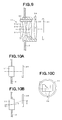
- FIG. 9 is a cross-sectional diagram according to the first embodiment, illustrating one example of the configuration of the photographing optical system.
- FIG. 10A , FIG. 10B , and FIG. 10C are side cross-sectional views and a front view diagram according to the first embodiment, illustrating a case of changing the center axis of the photographing luminous flux of the photographing optical system.
- FIG. 11A and FIG. 11B are a side cross-sectional diagram and a front view diagram according to the first embodiment, illustrating the another example of changing the center axis of the photographing luminous flux.
- FIG. 12A and FIG. 12B are diagrams according to a second embodiment of the present invention, illustrating the configuration of a camera wherein the frame unit is attached to the main unit so as to be detachable.
- FIG. 13A is a perspective diagram according to a third embodiment of the present invention, from the front face side the main unit of a camera type wherein the frame unit is separated from the main unit.
- FIG. 13B is a perspective diagram according to the third embodiment, from the back side the frame unit of a camera type wherein the frame unit is separated from the main unit.
- FIG. 14 is a perspective diagram according to a fourth embodiment of the present invention, illustrating an example of a camera wherein the viewfinder is configured of a transmissive type display device.
- FIG. 15A is a perspective diagram according to a fifth embodiment of the present invention, illustrating the external view of the camera from the front face side.
- FIG. 15B is a perspective diagram according to the fifth embodiment, illustrating the external view of the camera from the back side.
- FIG. 16A is a perspective diagram according to a sixth embodiment of the present invention, illustrating the external view of the camera from the front face side.
- FIG. 16B is a perspective diagram according to the sixth embodiment, illustrating the external appearance of the camera from the back side.
- FIG. 17A is a rear view diagram illustrating a normal camera that has applied the back-face image-pickup unit relating to the present invention.
- FIG. 17B is a front view diagram illustrating a normal camera that has applied the back-face image-pickup unit relating to the present invention.
- FIG. 18 is a diagram illustrating the situation wherein framing is determined using a finger frame.
- FIG. 1A through FIG. 11B show a first embodiment of the present embodiment, wherein FIG. 1A is a perspective diagram illustrating the configuration of a camera from the back side, and FIG. 1B is a perspective diagram illustrating the configuration of a camera from the front face side.
- This camera 1 is configured as a digital camera, and a frame-shaped frame is used as framing means.
- This camera 1 is divided primarily into a main unit 1 a that has a function for picking up an image of a subject, and a frame unit 1 b as the framing means to set the photographing range (composition) of the subject.
- the above-mentioned main unit 1 a comprises a camera main unit 2 wherein one portion also includes a gripping unit 2 a , a photographing optical system 11 positioned on the front face side of this camera main unit 2 and configured as a zoom optical system for forming images of the subject image, a flash unit 12 positioned on for example the upper side of this photographing optical system 11 for casting light to the subject, a shutter button 7 that is the picture-taking instruction input means, positioned so as to form recessed face on the upper side of the above-mentioned camera main unit 2 , a display unit 8 positioned on the back face side of this camera main unit 2 , a media slot 13 positioned on the lower side of the side face of this camera main unit 2 , and a battery attachment 15 positioned on the bottom side of this camera main unit 2 , as shown in FIG. 1A through FIG. 1B .
- the display unit 8 is used to display the various information relating to this camera 1 , while also being used to confirm the image after picture-taking.
- a liquid crystal display device which is in color and which provides a certain degree of fineness, whereby confirmation can be made of the image, is assumed as the display unit 8 , but in the case of configuring a camera at low cost, a black-and-white type of display device that only is capable of displaying the various information can be used, and further, an arrangement may be made wherein no such display device is provided at all.
- the photographing optical system 11 is configured as a zoom optical system. This optical system 11 is capable of changing the focal length, as described above, and further, is configured so as to be able to change the photographing direction when as a whole image-pickup system, combined with the CCD 25 (see FIG. 5 , FIG. 9 through FIG. 11B ) to be described later.
- the above-mentioned shutter button 7 is configured with for example a touch sensor and so forth, and unlike a normal camera, is configured so as to be able to input picture-making operation instructions simply by lightly touching instead of pushing the button. Therefore, in order to prevent erroneous operation, it is positioned within a recessed face as described above.
- the above-mentioned media slot 13 is for attaching a memory medium 14 such as for example a memory card, in a detachable manner.
- the above-mentioned battery attachment unit 15 is configured for the battery 16 to be attached in a detachable manner.
- a system that uses a fuel battery can be utilized instead of a system that uses a storage battery, and instead of the above-mentioned battery 16 , a fuel cartridge can be attached in a detachable manner.
- the above-mentioned frame unit 1 b comprises a first L-shaped frame 3 disposed as one unit being integrated with from the side portion of the main unit 1 a as described above, and a second L-shaped frame 4 provided so as to be capable of moving relative to this L-shaped frame 3 , and a viewfinder 5 is a two-dimensional region formed by combining the L-shaped frame 3 and the L-shaped frame 4 .
- the L-shaped frame 3 and the L-shaped frame 4 are capable of moving relative to each other, as will be described below, but this viewfinder 5 does not specify the largest opening that the L-shaped frame 3 and the L-shaped frame 4 could form, but rather specifies the size of frame opening that the combination of the L-shaped frame 3 and the L-shaped frame 4 currently form.
- the above-mentioned L-shaped frame 3 comprises a vertical frame 3 a that forms the left side of the above-mentioned viewfinder 5 when viewed from the back, and a horizontal frame 3 b that forms the bottom side of this viewfinder 5 , and on the end portion of this horizontal frame 3 b is formed a holding unit 3 c for holding this frame 1 b with the hand.
- the above-mentioned L-shaped frame 4 comprises a vertical frame 4 a that forms the right side of the above-mentioned viewfinder 5 when viewed from the back, and a horizontal frame 4 b that forms the upper side of this viewfinder 5 , and on the upper right corner wherein the above-mentioned vertical frame 4 a and horizontal frame 4 b are linked is formed a gripping unit 4 c for holding with the hand in the event of moving this L-shaped frame 4 .
- connection groove 3 d On the vertical frame 3 a of the above-mentioned first L-shaped frame 3 is formed a connection groove 3 d , and on the horizontal frame 3 b is formed a connection groove 3 e , and into this connection groove 3 d the above-mentioned horizontal frame 4 b is inserted so as to be capable of sliding, and into this connection groove 3 e the above-mentioned vertical frame 4 a is inserted so as to be capable of sliding.
- the size or aspect ratio of the above-mentioned viewfinder 5 can be changed as desired within a predetermined range in the condition wherein the vertical frame 3 a and vertical frame 4 a remain parallel to each other, and the horizontal frame 3 b and the horizontal frame 4 b remain parallel to each other.
- a back-face image-pickup device 6 a , 6 b , and 6 c are positioned respectively.
- These back-face image-pickup devices 6 a , 6 b , and 6 c are configured using an image-pickup device that is relatively inexpensive and has a small power consumption such as for example a CMOS sensor, and are provided to confirm the eye position of the face of the photographer.
- these back-face image-pickup devices 6 a , 6 b , and 6 c do not need to be color image-pickup devices, but can be black-and-white type of image-pickup devices.
- a minimum of two image-pickup devices will suffice, but here, in order to raise the level of measurement accuracy, and in order to remain capable of measurement in the event that one of the image-pickup devices is shielded by a hand or another obstruction, three image-pickup devices are provided.
- an arrangement may be made wherein only two image-pickup devices are provided.
- each back-face image-pickup device may be provided. Further, positioning each back-face image-pickup device apart from one another within a feasible range is desirable to increase measurement accuracy (particularly the measurement accuracy relating to distance).
- a back illumination unit 9 which is back illumination means for casting infrared light toward the back at this camera back side.
- This back illumination unit 9 is provided to illuminate the direction of the face of the photographer in a dark place and so forth, and so the light will not be a distraction to the photographer taking the photograph, infrared light is used in place of visible light.
- the above-mentioned back-face image-pickup devices 6 a , 6 b , and 6 c would also need to use the type of image-pickup devices that can pick up images with infrared light, as a matter of course.
- FIG. 2 is a perspective diagram illustrating from the back side of the camera the situation wherein a photographer is holding a camera for picture-taking
- FIG. 3 is a perspective diagram illustrating from the back side of the camera the situation of holding a camera and changing the size of the viewfinder.
- the grip unit 2 a of the camera 1 is held with the left hand, and with the left arm stretched out a certain amount, the composition is determined by moving the arm and so forth while observing the subject via the above-mentioned viewfinder 5 until the desired composition is completely inside this viewfinder 5 , and picture-taking can be performed by touching the above-mentioned shutter button 7 with for example the forefinger of the left hand.
- the above-mentioned gripping unit 4 c is gripped with for example the forefinger and thumb of the right hand, and size of the above-mentioned viewfinder 5 can be changed.
- the size of the viewfinder 5 is reduced without the aspect ratio changing, this equates zooming, and if the ratio of the length of the vertical direction and the length of the horizontal direction of the viewfinder 5 is changed, the aspect ratio is changed.
- the configuration is such that zooming can also be performed by bringing back the left arm that is holding the camera 1 and changing the distance between the camera 1 and the eye of the photographer. As will be described in greater detail below, this is performed by the image of the face side of the photographer being captured by the above-mentioned back-face image-pickup devices 6 a , 6 b , and 6 c , the distance and angles of the camera 1 and the eye of the photographer being calculated based on the image-picked-up data, and changing the center axis of the photographing luminous flux or zooming based on this calculated data.
- FIG. 4A and FIG. 4B are perspective diagrams illustrating from the back side of the camera the situation wherein the viewfinder 5 is changed when the gripping unit 4 c is operated.
- FIG. 4A illustrates the state of the viewfinder 5 wherein the picture is to be taken with an aspect ratio with a long horizontal side, which equates to a so-called panorama image.
- FIG. 4B illustrates the state of the viewfinder 5 wherein the aspect ratio is adjusted so that the image will be somewhat longer vertically, and in the
- FIG. 5 is a block diagram illustration the principal parts of the primarily electric configuration of a camera 1 .
- This camera 1 comprises a back illumination unit 9 ; a back-face image-pickup unit 6 which is eye position detecting means that is configured by including the above-mentioned back-face image-pickup devices 6 a , 6 b , and 6 c ; a frame size detecting unit 22 , which is frame geometric property detecting means for detecting the length in the vertical direction and the length in the horizontal direction of the above-mentioned viewfinder 5 each as geometric properties; the above-mentioned display unit 8 ; a back side image analyzing unit 23 , which is back side image analyzing means for calculating the distance and direction from the predetermined reference position of this camera 1 to the eye of the photographer, by analyzing the image at the camera back side that is captured by the above-mentioned back-face image-pickup unit 6 ; a CCD 25 , which is an image-pickup device and photographing means, for converting the optical subject images formed by the above-mentioned photographing optical system 11 into an electronic image signal; an image processing unit
- FIG. 6 is a flowchart illustrating a summary of the operation of the camera when the power is turned on.
- the power of this camera 1 is turned on by operating the power switch of the above-mentioned operation input unit 29 , and first, checking and initialization of the various module of this camera 1 are performed (step S 1 ). Then whether or not the check results are OK is determined (step S 2 ), and the flow returns to the above-mentioned step S 1 and checks until the result is OK.
- the size u of the vertical direction of the viewfinder 5 and the size v of the horizontal direction are captured by the above-mentioned frame size-detecting unit 22 (step S 3 ).
- step S 4 the image at the back side of the camera 1 is captured by the above-mentioned back-face image-pickup unit 6 (step S 4 ).
- illumination is performed by casting infrared light by the above-mentioned back illumination unit 9 .
- step S 5 determination is made as to whether the number of the captured back images is two or greater.
- the number of the captured back images is two or greater.
- step S 5 in the case that the determination is made that two or more back images are captured, the captured back images are each analyzed by the above-mentioned back image analyzing unit 23 , and the open eyes are detected (step S 6 ).
- step S 7 based on the number of open eyes, the process branches (step S 7 ).
- FIG. 7 is a perspective diagram, describing the three-dimensional eye position of the photographer in relation to the camera 1 .
- the center position P of the above-mentioned viewfinder 5 is set as the predetermined reference position of the camera 1 that is to be the basis for detecting the position of the eye E of the photographer.
- This center position P is a position wherein the two diagonal lines of the viewfinder 5 that form a rectangle intersect.
- the above-mentioned predetermined reference position does not need to be limited to this center position P, and can be set appropriately, but here for the ease of calculations of the above-mentioned x, ⁇ , and ⁇ , and so forth, the above-mentioned center position P is set.
- the above-mentioned distance x is defined as the distance between this center position P and the eye E of the photographer.
- a vertical line VL that passes through the above-mentioned center position P and is parallel in the vertical direction of the viewfinder 5 and a horizontal line HL that passes through the above-mentioned center position P and is parallel in the horizontal direction of the viewfinder 5 are considered.
- the above-mentioned angle ⁇ is defined as an angle formed by the line segment that ties the above-mentioned center position P and the eye E of the photographer, and the above-mentioned vertical line VL
- the above-mentioned angle ⁇ is defined as an angle formed by the line segment that ties the above-mentioned center position P and the eye E of the photographer, and the above-mentioned horizontal line HL.
- FIG. 8 is a diagram describing the angle ⁇ made by the horizontal direction of the photographer and the horizontal direction of the camera.
- the horizontal direction of the camera 1 may differ from the horizontal direction of the photographer.
- the angle that is formed in this case is the angle ⁇ .
- This angle ⁇ can be defined as, for example, the angle that is formed by the line that is obtained by connecting both eyes of the photographer and projected onto the plane that forms the viewfinder 5 , and the above-mentioned horizontal line HL ( FIG. 8 illustrates the angle ⁇ as the angle that is formed by the line that is obtained by connecting both eyes of the photographer and the line that is formed by projecting this horizontal line HL onto the plane that forms the body front of the photographer, and this is the equivalent of the above).
- step S 9 determination is made as to whether or not the size u of the vertical direction and size v of the horizontal direction of the viewfinder 5 captured as described above, and x, ⁇ , and ⁇ calculated as described above are within the allowable range (step S 9 ).
- the optical axis of the photographing optical system 11 is set based on the direction determined by the above-mentioned angles ⁇ and ⁇ (step S 10 ).
- the center axis of the photographing luminous flux is set to match to the direction determined by these angles ⁇ , and ⁇ , and further, in the case wherein adjustment of the photographing direction is not possible with the optical means alone, settings are made to be nearer to the direction determined by the angles ⁇ , and ⁇ as much as possible.
- shifting is performed of the electronic image center by changing the center position of the cropping range of the image at a later time.
- the optical zoom is set based on the above-mentioned u, v, x (step S 11 ).
- the optical zoom is changed to the magnification determined by the above-mentioned u, v, and x, but in the case that it is not possible with the optical zoom alone, settings are made to near the magnification determined by the above-mentioned u, v, and x, as much as possible.
- the magnification is set as determined by this u, v, and x, by combining with the electronic zoom at a later time.
- the electronic zoom and aspect ratio is set (step S 12 ).
- the cropping range is also changed based on the above-mentioned angles ⁇ and ⁇ .
- the image is captured by the above-mentioned CCD 25 , and image processing is performed by the above-mentioned image processing unit 24 (step S 13 ).
- the frame image newly captured in this manner is overwritten on the oldest frame image within the frame images stored in the frame buffer of the internal memory 21 (step S 14 ).
- a memory region serving as a frame buffer is secured wherein the image data for only a predetermined number of frames can be stored, which are stored in units of frames in the order of FIFO (First In, First Out). Therefore, after the predetermined number of frames worth of image data is stored, the oldest image data is overwritten in order by the newest image data.
- FIFO First In, First Out
- an OK sign is displayed indicating that the picture-taking has been performed with no impediment (step S 15 ), using the above-mentioned display unit 8 and so forth.
- the OK sign is not limited to a display only, but can be performed for example by audio, or by a combination of display and audio.
- the flow returns to the above-mentioned step S 3 , and repeats the above described operation.
- the above described series of photographing operations are constantly repeated, and when the above-mentioned shutter button 7 is touched during the performance of these operations, the image that is photographed at that time is recorded for example in a file format as the photographed image to the above-mentioned recording medium 14 .
- the shutter button 7 is a type as described above that is operated simply by being lightly touched instead of being pressed down. By doing so, the camera has excellent operability wherein the awkwardness felt by the photographer at the time of picture-taking is further reduced.
- step S 5 in the case that the number of captured images is one or less, determination is made as to whether or not the non-frame photographing mode is set, which can be set as an option with this camera 1 (step S 16 ).
- This non-frame photographing mode does not set the range observed via the above-mentioned viewfinder 5 as the photographing range, but rather is a mode wherein picture-taking is performed as set according to the predetermined zoom position and the predetermined photographing direction.
- This type of non-frame photographing mode is a photographing mode provided for use, for example, in the case wherein a photojournalist desires to take the image of a subject while holding his/her hand high over his/her head, or in the case of facing the photographing optical system 11 of the camera 1 towards oneself and holding ones hand out and photographing oneself.
- the data set as the third option data is read, and the flow continues to the processing of the above-mentioned step S 8 .
- X0 the statistics of the distance x to the eye of the photographer using this camera 1 can be acquired, and the average value thereof may be used. Further, based on the statistics, the correlation between (u+v) and x can be determined, and the above-mentioned constant k can be decided as applicable.
- step S 16 the number of back images in order for photographing with the frame photographing mode is insufficient, and because the distance or angle to the eye of the photographer cannot be correctly measured, a warning is performed as the first warning (step S 17 ), and the flow returns to the above-mentioned step S 3 .
- step S 7 In the case that the number of open eyes in the above-mentioned step S 7 is 0, detection of closed eyes or sunglasses is performed, and based on the detection results the estimated eye position is calculated (step S 18 ).
- step S 19 determination is made whether or not a reasonable estimated eye position is decided. In the case that the eye position is determined, or if setting is such that the third option data as described above is used as the estimated value, the flow continues to the processing of the above-mentioned step S 8 .
- a warning is performed as the second warning (step S 20 ), and the flow returns to the above-mentioned step S 3 .
- the number of open eyes in the above-mentioned step S 7 is two or more, first the above-mentioned x, ⁇ , and ⁇ are calculated for each of the open eyes (step S 21 ), and based on the calculation results, the eye closest to the above-mentioned center position P is selected (step S 22 ).
- the closest eye to the center position P is selected, but instead of doing so, the so-called stronger eye can be estimated based on the back images, and the estimated stronger eye can be selected.
- the stronger eye can be selected using the first option data.
- the first option data is the stronger eye data set by the user, and can be selected from the setting items of left eye, right eye, or no setting.
- step S 9 in the case that determination is made that the calculated x, ⁇ , and ⁇ are not within the allowable range, an approximation of x, ⁇ , and ⁇ is performed so as to be within the allowable range (step S 23 ).
- step S 24 Determination of whether or not these approximated x, ⁇ , and ⁇ are valid is made referencing the second option data (step S 24 ), and in the case they are determined to be valid, the flow continues to the processing in the above-mentioned step S 10 .
- the second option data are stored the classification of the approximation levels, and the breakdown thereof is (1) the case wherein x, ⁇ , and ⁇ are not capable of being approximated, (2) the case wherein approximation relating to x can deal with the situation, (3) the case wherein approximation relating to ⁇ , and ⁇ alone can deal with the situation, and (4) the case wherein the situation can be dealt with if all of x, ⁇ , and ⁇ are approximated. Of these, (2) through (4) are determined to be reasonable, while (1) is determined not to be reasonable.
- step S 25 a warning is performed as the third warning (step S 25 ), and the flow returns to the above-mentioned step S 3 .
- FIG. 9 is a cross-sectional diagram illustrating one example of the configuration of the photographing optical system.
- the photographing optical system 11 for example comprises lenses 31 a , 31 b , and 31 c that are positioned on a zoom lens frame 32 , and a lens 33 that is positioned on the lens frame 34 that supports this zoom lens frame 32 at least so as to be capable of movement in the optical axis direction.
- the above-mentioned lens frame 34 is fixed to the camera main unit 2 for example.
- a CCD 25 is positioned so as to match the center position of that image pickup plane onto this optical axis.
- This type of positioning wherein the center position of the image pickup plane of the CCD 25 is matched to the optical axis of the photographing optical system 11 is the standard positioning for this camera 1 .
- change to the focal length of the photographing optical system 11 is performed by moving the above-mentioned lenses 31 a , 31 b , 31 c that make up a zoom lens group in the direction of the optical axis via the above-mentioned zoom lens frame 32 .
- FIG. 10A , FIG. 10B , and FIG. 10C are side cross-sectional diagrams and a front view diagram illustrating the situation of changing the center axis of the photographing luminous flux of the photographing optical system.
- FIG. 10A is a diagram illustrating the standard positioning illustrated in the above-mentioned FIG. 9 in a simplified manner.
- FIG. 10B and FIG. 10C illustrate the situation wherein the CCD 25 is viewed from the front, shifted to the upper left by the shifting means, and is a positioning wherein the center axis of the photographing luminous flux forms the predetermined angle 0 against the optical axis of the photographing optical system 11 , and also the center position of the image pickup plane on the CCD 25 is shifted from the optical axis by the amount illustrated by the arrows in FIG. 10B or FIG. 10C .
- the shifting means are not specifically illustrated, but a wide variety of means for shifting the position of the CCD 25 in the direction of intersecting with the optical axis can be applied, using a drive source such as a motor or a solenoid plunger.
- the above-mentioned angle ⁇ is set according to the detected angles ⁇ and ⁇ , as described above. By doing so, even if the photographer is observing the viewfinder 5 from a diagonal direction, the field of view range that the photographer is observing via this viewfinder 5 at this time can be set approximately accurately as the region of the photographing object, and picture-taking can be performed.
- FIG. 11A and FIG. 11B are a side cross-sectional diagram and a front view diagram illustrating another example of changing the center axis of the photographing luminous flux.
- the above-mentioned photographing optical system 11 is configured including for example lenses 35 a , 35 b , and 35 c , as illustrated in FIG. 11A .
- Each of these lenses 35 a , 35 b , and 35 c are supported by the lens frame 36 that forms an approximately spherical shape, so as to be capable of moving in the optical axis direction when performing focus operations or zooming operations.
- a CCD 25 On the image forming position from the above-mentioned lenses 35 a , 35 b , and 35 c within this lens frame 36 is positioned a CCD 25 , so as to output the image signal obtained from the photoelectric conversion to the above-mentioned image processing unit 24 that is provided on the inner portion of the camera main unit 2 .
- the above-mentioned lens frame 36 is held by the approximately spherical lens frame holding unit 37 of the camera main unit 2 so as to be capable of rotating, and the side that is holding the above-mentioned lenses 35 a , 35 b , and 35 c is exposed from the opening unit 37 a that is provided on the camera front face side of this lens frame holding unit 37 (also see FIG. 11B ), and on the other hand, the cables and so forth extending from the above-mentioned CCD 25 are formed so as to be extracted from the opening unit 37 b provided on the camera inner portion side of the lens frame holding unit 37 .
- the above-mentioned lens frame 36 floats so as to not be in contact with the above-mentioned lens frame holding unit 37 , by using magnetic power for example, and when rotational power is added, it rotates freely with the freedom level 2 around the center of the spherical form, within the predetermined allowable range.
- addition of the rotational force can be performed by changing the magnetic strength that holds the floating state, or performed by another mechanical type of power.
- an outer zoom type of optical system is illustrated in the above described example, wherein the front edge side of the photographing optical system 11 is exposed to the outside of the lens frame 36 , but in the event that an inner zoom type of optical system is used instead, a configuration can be realized without protruding, and the freedom level of rotation can be maintained more widely, and therefore from this viewpoint, and from the viewpoint of protecting the photographing optical system 11 , this is more desirable.
- relating to focus either an outer focus or an inner focus can be used, but the inner focus is more desirable.
- the above-mentioned L-shaped frames 3 and 4 are assumed to be formed of a normal material that is not transparent, for example a plastic that is not transparent, but do not need to be limited to this, and a material with a partial transparency rate of, for example, several percent to several tens of percent (for example a smoked glass or a smoked form of plastic) may be used to form this.
- a material with a partial transparency rate of, for example, several percent to several tens of percent for example a smoked glass or a smoked form of plastic
- the configuration can be such that scales and so forth are provided on the back side of the above-mentioned first L-shaped frame 3 and the second L-shaped frame 4 (in other words, the side that is viewable by the photographer), and the measurements of the viewfinder 5 can be accurately grasped.
- the configuration can be opposite left and right, wherein the gripping unit is provided so as to hold with the right hand, and the gripping unit can be provided to operate with the left hand.
- the operation thereof would become somewhat more difficult, but the camera could be held with one hand and adjustments of the viewfinder could be made with that same holding hand.
- the first L-shaped frame 3 itself and the second L-shaped frame 4 itself were both fixed members, but for example, a configuration can be made which enables being folded up during periods of non-use, by providing a hinge and so forth on the corner unit of these members that form the L-shape.
- an enclosing unit can be provided within the above-mentioned gripping unit 2 a , and the folded L-shaped frames 3 and 4 can be enclosed in the inner portion.
- the transparent plate member such as the glass plate or transparent plastic plate is not particularly imbedded into the portion of the viewfinder 5 , but these can be formed by imbedding.
- adding a grid of index lines for example to the transparent plate member can be used for determining composition.
- multiple transparent plate members possessing multiple index lines of different types can be prepared, such as a transparent plate member comprising a grid of index lines with rough spacing, a transparent plate member comprising a grid of index lines with fine spacing, a transparent plate member comprising index lines of the golden ratio, and so forth, and these can be made interchangeable.
- index lines are drawn so as to divide the above-mentioned viewfinder 5 in the predetermined distribution, and one line can be used, or multiple lines can be combined. Further, not only can index lines be used, but also shapes, designs, or colors that can serve as an aid in determining the composition, or a combination thereof, can be used.
- the back side image is captured by using a CMOS type image-pickup device for example, and the eye position of the photographer is detected by analyzing the captured image, but the eye position detecting means does not need to be limited to this, and means to detect the eye position such as an infrared or laser light and so forth, can be used. In the case of using these other means, using detecting means that does not interfere with picture-taking is desirable.
- the image range viewed via the viewfinder can be taken as is, and therefore the picture-taking can be performed with a natural sensation without feeling any awkwardness.
- standard cameras can only take images with a limited aspect ratio in steps such as normal picture-taking or panorama picture-taking, but according to the camera of the present embodiment, the aspect ratio of the image can be set continuously as desired, within a predetermined range.
- the object of detection is not the movement of the eyeball of the photographer, but rather is the eye position of the photographer, and therefore highly accurate and expensive detecting devices and so forth are not necessary, and the camera can be configured at a relatively low cost.
- FIG. 12A and FIG. 12B illustrate a second embodiment according to the present invention, and are diagrams illustrating the configuration of a camera wherein the frame unit is attached to the main unit so as to be detachable.
- the camera according to this second embodiment is configured so that the frame unit 1 B which is the first camera unit and framing means for setting the photographing range of the subject can be attached so as to be detachable from the main unit 1 A of the second camera unit having the function for capturing the image of a subject.
- a connector unit 41 is provided on the main unit 1 A, and a connector unit 42 is provided on the frame unit 1 B for this connector unit 41 to connect.
- the above-mentioned main unit 1 A can be used as a camera for capturing the image of a subject as an independent unit, and as illustrated in FIG. 12A , in the state wherein it is separated from the frame unit 1 B, the photographing range is decided using the above-mentioned display unit 8 , and picture-taking is performed.
- the composition can be determined by changing the size of the above-mentioned viewfinder 5 or moving the arm closer or further that is holding the camera, and thereby changing the accompanying zooming operation or center axis of the photographing luminous flux.
- picture-taking with only the main unit is can be realized because the main unit and the frame unit can be separated, and therefore, according to the preference of the user, or in the case of multiple users taking turns using one camera, the desired photographing method can be selected according to the expertise and preferences of each user, and thus the camera has even better operability.
- FIG. 13A and FIG. 13B illustrate a third embodiment according to the present invention, wherein FIG. 13A is a perspective diagram illustrating from the front face side the main unit of a camera type wherein the frame unit is separated from the main unit, and FIG. 13B is a perspective diagram illustrating from the back side the frame unit of a camera type wherein the frame unit is separated from the main unit.
- This camera is configured such that the frame unit 1 B is a separate unit from the main unit 1 A, wherein a wireless transmitting unit 45 which is a communication means is provided on the main unit 1 A, and a wireless transmitting unit 46 which is a communication means is provided on the frame unit 1 B, and the units can transmit wirelessly with each other.
- the wireless transmitting units 45 and 46 are configured so as to be used as relative angle detecting means to detect the relative angles of the frame unit 1 B to the main unit 1 A.
- This relative angle detecting means is specifically a means that uses a transmitting method of magnetic induction, for example.
- This transmitting method is a transmitting method that generates a magnetostatic field, and at the same time applies a low frequency electromagnetic field onto this magnetostatic field, and uses the changes generated thereby, and the antenna used for transmissions is a magnetic dipole antenna (specifically, a bar coil).
- a magnetic dipole antenna specifically, a bar coil
- the size of the induced current is dependent on the relative tilt of both dipole axes, due to the magnetic characteristics of the magnetic dipole, wherein the size is greatest in the case that both dipole axes are parallel to one another, and is smallest in the case that both dipole axes are perpendicular to one another.
- the wireless transmitting unit 45 of the above-mentioned main unit 1 A is configured with a transmission antenna in the form of two orthogonal magnetic dipoles
- the wireless transmitting unit 46 of the above-mentioned frame unit 1 B is configured with a transmission antenna in the form of three orthogonal magnetic dipoles.
- the wireless transmission between the frame unit 1 B and the main unit 1 A using the above described wireless transmitting units 45 and 46 is accomplished by for example using the same frequency wave of a low frequency for both sending and receiving, and dividing into a time axis, and switching between sending and receiving at a high speed.
- the relative tilt of the above-mentioned frame unit 1 B to the main unit 1 A is defined by each magnetic dipole antenna on one side of the main unit 1 A and the frame unit 1 B measuring the inducted current signal of each magnetic dipole antenna on the other side.
- a shutter button 7 a which is picture-taking instruction input means
- a shutter button 7 b which is picture-taking instruction input means
- the power for the frame unit 1 B is transmitted wirelessly for example from the main unit 1 A.
- this does not need to be a limitation, and a detachable battery may be built into the frame unit 1 B.
- the main unit 1 A When performing picture-taking with this type of camera configuration, first the main unit 1 A is placed so that the photographing optical system 11 thereof approximately points toward the subject. Then, the photographer holds only the frame unit 1 B by hand, and the composition of the subject is determined via the viewfinder 5 .
- the information of the subject range observed by the photographer and the angle information of the frame unit 1 B to the main unit 1 A is continuously transmitted to the main unit 1 A side via the above-mentioned wireless transmitting units 45 and 46 , and as the main unit 1 A is described, the photographing range is determined based on this information, and continuously accumulates photographed images to the frame buffer that is capable of recording the image data of several frames worth.
- the picture-taking command is transmitted to the main unit 1 A side, and the newest frame image is recorded on the above-mentioned recording medium 14 as a file.
- this camera can perform picture-taking with the individual main unit 1 A by itself, and the photographing operation is performed by touching the above-mentioned shutter button 7 a.
- composition decisions and photographing operations can be easily performed because picture-taking can be performed by holding only the frame unit in the hand.
- the tilt can be detected, and an image with a composition taking the tilt into account can be taken.
- FIG. 14 is a perspective diagram according to a fourth embodiment of the present invention, illustrating an example of a camera where the viewfinder is configured using a transmissive-type display device.
- This camera is configured wherein the viewfinder 5 is a transmissive-type display device, for example a transmissive-type LCD.
- the frame unit 1 b comprises a transmissive type display device 52 within an outer frame 51 , and for example on the upper right portion a view-finding operating member 53 is provided.
- the above-mentioned transmissive type display device 52 displays a transparent region 52 a in the center, and displays a semi-transparent region 52 b on the outer side of this transparent region 52 a , and the boundary line 5 a of these regions defines the range of the viewfinder 5 .
- the above-mentioned view-finding operating member 53 is configured as a lever member that can move in four directions lengthwise and crosswise, for example.
- the back-face image-pickup device 6 b is positioned on the camera main unit 2 side.
- operation of the lever in not only the four directions, but also in diagonal directions, may be configured, to facilitate even easier operation.
- a lever member is used to operate the range of the viewfinder 5 , but this does not need to be a limitation, and it goes without saying that the range of the viewfinder 5 may be operated using for example a touch panel type transmissive display device with a separate pen to operate.
- the transparent region 52 a as described above is basically for allowing light to pass through, but as described in the first embodiment, a grid of index lines or golden ratio index lines serving as a reference for determining the composition may be used for display, and not only index lines, but shapes, designs, colors, or a combination thereof that would be an aid to determining the composition may be used for display.
- FIG. 15A and FIG. 15B illustrate a fifth embodiment of the present invention, wherein FIG. 15A is a perspective diagram illustrating the external view of the camera from the front face side, and FIG. 15B is a perspective diagram illustrating the external view of the camera from the back side.
- This camera according to the fifth embodiment is configured wherein the viewfinder is a non-transmissive type display device.
- a non-transmissive type display device 55 is positioned on the back face of the camera. Further, surrounding this display device 55 are positioned back-face image-pickup devices 6 a through 6 d , and in this fifth embodiment, the number of back-face image-pickup devices is increased to four. Further, the back illumination unit 9 being positioned on the periphery of the above-mentioned display device 55 is similar to that described above.
- the photographing range viewed by the photographer is estimated, based on the information of the eye position of the photographer that is detected by the above-mentioned back-face image-pickup devices 6 a through 6 d , zoom position or photographing direction is adjusted by the photographing optical system 11 illustrated in FIG. 15A or the above-mentioned image processing unit 24 , so that the image in the estimated photographing range can be obtained, and the image of the estimated photographing range is captured, and that image is displayed on the display device 55 , thereby accomplishing the function of a viewfinder.
- FIG. 16A and FIG. 16B illustrate a sixth embodiment of the present invention, wherein FIG. 16A is a perspective diagram illustrating the external view of the camera from the front face side, and FIG. 16B is a perspective diagram illustrating the external view of the camera from the back side.
- the camera according to this sixth embodiment comprises a viewfinder 5 of a fixed size.
- this camera does not combine multiple L-shaped frames, but rather comprises a fixed viewfinder 5 formed of an approximately rectangle shape.
- the photographing optical system 11 comprises for example a lens with a single focal point, and zooming operation is enabled only with an electronic zoom.
- a flash unit 12 is positioned on the upper side of the above-mentioned photographing optical system 11 , a battery attaching unit 15 for attaching a battery 16 is positioned on the bottom side, a media slot 13 for attaching a recording medium 14 is positioned on the side face, and the above-mentioned back-face image-pickup devices 6 a through 6 d and the back illumination unit 9 are positioned on the back face.
- a first shutter button 7 a is positioned, and on the left side a second shutter button 7 b is positioned, and is so configured that a photographing operation can be performed with either the right hand or the left hand as desired, or a photographing operation can be performed easily when the camera is held in a vertical position or held in a horizontal position.
- the photographing optical system 11 has been described as having a single focal point, but it goes without saying that an optical system capable of zooming can be used.
- a photographing optical system 11 that can change the photographing direction is assumed in the description above, but the photographing direction may be optically unchangeable. When doing so, electronic changes to the photographing direction can be made by setting the cropping range of the image. By utilizing such a configuration, the cost of the camera can be lowered even further.
- the technology for detecting the eye of the photographer used the above-described back-face image-pickup devices 6 a through 6 d does not need to be limited to the type of camera that uses a viewfinder to determine the composition, and can be applied to a normal camera as well.
- FIG. 17A is a rear view diagram illustrating a normal camera that has applied the back-face image-pickup unit
- FIG. 17B is a front view diagram illustrating a normal camera that has applied the back-face image-pickup unit.
- This camera 91 comprises a photographing optical system 94 and a flash unit 95 on the front face side of the camera main unit 92 , a shutter button 97 on the upper face, and further, the optical finder 98 is positioned with the object side on the front face side and the eye side on the back face side, each exposed, as illustrated in FIG. 17B .
- the back-face image-pickup devices 6 a through 6 d as described above, and a back illuminating unit 9 are positioned, as illustrated in FIG. 17A .
- This type of camera 91 can also be effectively used for detecting the eye position of the photographer, and using the detected information for picture-taking preparation operations or other processing.
- each of the above-described embodiments primarily describe a camera that electronically takes still images, such as a digital camera, but the present invention is not restricted to this, and can be applied to a camera that electronically takes moving images such as a video camera, or can be applies to a silver salt camera that performs exposure onto a silver salt film, or can be applied to various equipment having camera functions (for example, a cellular telephone with a camera function).
- each of the above-described embodiments uses a rectangular frame as a viewfinder
- the present invention is not limited to a rectangular viewfinder, and various shapes of viewfinders may be used, in the same way as artwork that is drawn to be framed in for example a round-shaped or oval-shaped frame.
Abstract
Description
Claims (24)
Priority Applications (1)
| Application Number | Priority Date | Filing Date | Title |
|---|---|---|---|
| US12/786,200 US8040420B2 (en) | 2003-10-15 | 2010-05-24 | Camera |
Applications Claiming Priority (2)
| Application Number | Priority Date | Filing Date | Title |
|---|---|---|---|
| JP2003355591A JP5093968B2 (en) | 2003-10-15 | 2003-10-15 | camera |
| JP2003-355591 | 2003-10-15 |
Related Child Applications (1)
| Application Number | Title | Priority Date | Filing Date |
|---|---|---|---|
| US12/786,200 Division US8040420B2 (en) | 2003-10-15 | 2010-05-24 | Camera |
Publications (2)
| Publication Number | Publication Date |
|---|---|
| US20050122401A1 US20050122401A1 (en) | 2005-06-09 |
| US7750966B2 true US7750966B2 (en) | 2010-07-06 |
Family
ID=34613115
Family Applications (2)
| Application Number | Title | Priority Date | Filing Date |
|---|---|---|---|
| US10/947,057 Expired - Fee Related US7750966B2 (en) | 2003-10-15 | 2004-09-22 | Camera with framing means |
| US12/786,200 Expired - Fee Related US8040420B2 (en) | 2003-10-15 | 2010-05-24 | Camera |
Family Applications After (1)
| Application Number | Title | Priority Date | Filing Date |
|---|---|---|---|
| US12/786,200 Expired - Fee Related US8040420B2 (en) | 2003-10-15 | 2010-05-24 | Camera |
Country Status (3)
| Country | Link |
|---|---|
| US (2) | US7750966B2 (en) |
| JP (1) | JP5093968B2 (en) |
| CN (1) | CN100541313C (en) |
Cited By (4)
| Publication number | Priority date | Publication date | Assignee | Title |
|---|---|---|---|---|
| US20080159628A1 (en) * | 2006-12-27 | 2008-07-03 | Fujifilm Corporation | Image taking apparatus and image taking method |
| US8848088B2 (en) * | 2012-05-01 | 2014-09-30 | Xerox Corporation | Product identification using mobile device |
| US9076241B2 (en) | 2013-08-15 | 2015-07-07 | Xerox Corporation | Methods and systems for detecting patch panel ports from an image having perspective distortion |
| WO2015103211A1 (en) * | 2014-01-03 | 2015-07-09 | Lyve Minds, Inc. | Modular camera core |
Families Citing this family (52)
| Publication number | Priority date | Publication date | Assignee | Title |
|---|---|---|---|---|
| WO2006013803A1 (en) * | 2004-08-03 | 2006-02-09 | Matsushita Electric Industrial Co., Ltd. | Imaging device and imaging method |
| US20060209197A1 (en) * | 2005-03-15 | 2006-09-21 | Nokia Corporation | Camera devices |
| US8552988B2 (en) * | 2005-10-31 | 2013-10-08 | Hewlett-Packard Development Company, L.P. | Viewing device having a touch pad |
| WO2007082028A2 (en) * | 2006-01-11 | 2007-07-19 | Sony Corporation | Firmware updates on media |
| US20080002963A1 (en) * | 2006-06-28 | 2008-01-03 | Media Tek Inc. | Systems and methods for capturing images of objects |
| JP4959249B2 (en) * | 2006-08-01 | 2012-06-20 | 株式会社レクザム | Ophthalmic equipment |
| JP4463792B2 (en) | 2006-09-29 | 2010-05-19 | 富士フイルム株式会社 | Imaging device |
| KR100805452B1 (en) * | 2006-11-21 | 2008-02-20 | 현대자동차주식회사 | Mediation device for unfolding angle of air bag according to driver's head position and the method of the same |
| JP2008233381A (en) * | 2007-03-19 | 2008-10-02 | Fujifilm Corp | Imaging apparatus |
| US7639935B2 (en) * | 2007-03-28 | 2009-12-29 | Sony Ericsson Mobile Communications Ab | Zoom control |
| JP2009059257A (en) * | 2007-09-03 | 2009-03-19 | Sony Corp | Information processing apparatus and information processing method, and computer program |
| JP4991621B2 (en) * | 2008-04-17 | 2012-08-01 | キヤノン株式会社 | Imaging device |
| JP4725595B2 (en) * | 2008-04-24 | 2011-07-13 | ソニー株式会社 | Video processing apparatus, video processing method, program, and recording medium |
| CN101650627B (en) * | 2008-08-14 | 2011-02-02 | 鸿富锦精密工业(深圳)有限公司 | Electronic equipment and operating control method |
| JP5136326B2 (en) * | 2008-09-25 | 2013-02-06 | カシオ計算機株式会社 | IMAGING DEVICE, PROGRAM THEREOF, AND ELECTRONIC DEVICE |
| JP2010176170A (en) * | 2009-01-27 | 2010-08-12 | Sony Ericsson Mobilecommunications Japan Inc | Display apparatus, display control method, and display control program |
| JP4781440B2 (en) | 2009-02-05 | 2011-09-28 | ソニー エリクソン モバイル コミュニケーションズ, エービー | Image capturing apparatus, control method and control program for image capturing apparatus |
| US8314832B2 (en) * | 2009-04-01 | 2012-11-20 | Microsoft Corporation | Systems and methods for generating stereoscopic images |
| US20100296802A1 (en) * | 2009-05-21 | 2010-11-25 | John Andrew Davies | Self-zooming camera |
| JP5657235B2 (en) * | 2009-11-10 | 2015-01-21 | オリンパスイメージング株式会社 | Image capturing apparatus and image capturing method |
| US8957981B2 (en) | 2010-03-03 | 2015-02-17 | Intellectual Ventures Fund 83 Llc | Imaging device for capturing self-portrait images |
| US20120038663A1 (en) * | 2010-08-12 | 2012-02-16 | Harald Gustafsson | Composition of a Digital Image for Display on a Transparent Screen |
| JP5665434B2 (en) * | 2010-09-01 | 2015-02-04 | キヤノン株式会社 | Imaging apparatus, control method and program thereof, and recording medium |
| DE102010043919A1 (en) * | 2010-11-15 | 2012-05-16 | Leica Microsystems (Schweiz) Ag | Portable microscope |
| DE102010043917A1 (en) * | 2010-11-15 | 2012-05-16 | Leica Microsystems (Schweiz) Ag | Operating unit for a microscope |
| US9160931B2 (en) | 2011-04-08 | 2015-10-13 | Hewlett-Packard Development Company, L.P. | Modifying captured image based on user viewpoint |
| JP5861395B2 (en) * | 2011-11-02 | 2016-02-16 | リコーイメージング株式会社 | Portable device |
| US20140330900A1 (en) * | 2011-11-23 | 2014-11-06 | Evernote Corporation | Encounter-driven personal contact space |
| JP5978620B2 (en) | 2011-12-21 | 2016-08-24 | 株式会社リコー | Imaging device |
| KR101897549B1 (en) * | 2012-01-09 | 2018-09-12 | 삼성전자주식회사 | Apparatus and method for displaying camera view area in a portable terminal |
| JP5805013B2 (en) * | 2012-06-13 | 2015-11-04 | 株式会社Nttドコモ | Captured image display device, captured image display method, and program |
| JP6006024B2 (en) * | 2012-07-02 | 2016-10-12 | オリンパス株式会社 | Imaging apparatus, imaging method, and program |
| US8736692B1 (en) | 2012-07-09 | 2014-05-27 | Google Inc. | Using involuntary orbital movements to stabilize a video |
| KR101983288B1 (en) * | 2012-11-22 | 2019-05-29 | 삼성전자주식회사 | Apparatus and method for controlling a shooting status in a portable device having a dual camera |
| US20140184854A1 (en) * | 2012-12-28 | 2014-07-03 | Motorola Mobility Llc | Front camera face detection for rear camera zoom function |
| CN103327256A (en) * | 2013-07-05 | 2013-09-25 | 上海斐讯数据通信技术有限公司 | System and method for adjusting view-finding interface display image of mobile terminal camera |
| JP2015023512A (en) * | 2013-07-22 | 2015-02-02 | オリンパスイメージング株式会社 | Imaging apparatus, imaging method and imaging program for imaging apparatus |
| KR102254703B1 (en) * | 2014-09-05 | 2021-05-24 | 삼성전자주식회사 | Photographing apparatus and photographing method |
| CN105025224B (en) * | 2015-07-03 | 2018-01-19 | 广东欧珀移动通信有限公司 | A kind of photographic method and device |
| US10339661B2 (en) * | 2015-07-28 | 2019-07-02 | Panasonic Intellectual Property Management Co., Ltd. | Movement direction determination method and movement direction determination device |
| US20210168292A1 (en) * | 2015-12-22 | 2021-06-03 | Sharp Kabushiki Kaisha | Operation assistance device, operation assistance method, and recording medium |
| US9871962B2 (en) * | 2016-03-04 | 2018-01-16 | RollCall, LLC | Movable user interface shutter button for camera |
| CN105632286A (en) * | 2016-03-29 | 2016-06-01 | 重庆工业职业技术学院 | Photography view-finding demonstration teaching apparatus |
| CN106803894A (en) * | 2017-03-20 | 2017-06-06 | 上海与德科技有限公司 | Auto heterodyne reminding method and device |
| CN110520792B (en) * | 2017-03-30 | 2022-04-26 | 瑞典爱立信有限公司 | Imaging device and contact lens |
| JP6914158B2 (en) * | 2017-09-25 | 2021-08-04 | シャープ株式会社 | Distance measurement sensor |
| CN109839378B (en) * | 2017-11-24 | 2020-07-28 | 苏州精濑光电有限公司 | Rapid optical correction method |
| US11330209B2 (en) | 2018-03-29 | 2022-05-10 | Sony Semiconductor Solutions Corporation | Imaging device and electronic device enabled to control position of lens |
| JP2019184842A (en) * | 2018-04-11 | 2019-10-24 | ソニーセミコンダクタソリューションズ株式会社 | Imaging device and electronic apparatus |
| JP7224828B2 (en) * | 2018-09-27 | 2023-02-20 | キヤノン株式会社 | Imaging device |
| CN109120857B (en) * | 2018-10-29 | 2021-06-25 | 努比亚技术有限公司 | Shooting control method and device and computer readable storage medium |
| KR20220127815A (en) * | 2020-01-16 | 2022-09-20 | 소니그룹주식회사 | Display device, image creation method and program |
Citations (12)
| Publication number | Priority date | Publication date | Assignee | Title |
|---|---|---|---|---|
| US5252950A (en) | 1991-12-20 | 1993-10-12 | Apple Computer, Inc. | Display with rangefinder |
| US5335035A (en) * | 1992-02-24 | 1994-08-02 | Olympus Optical Co., Ltd. | Visual line direction detecting device for the camera |
| US5583606A (en) | 1987-06-11 | 1996-12-10 | Asahi Kogaku Kogyo Kabushiki Kaisha | Eye direction detecting apparatus |
| US5627621A (en) * | 1994-06-22 | 1997-05-06 | Olympus Optical Co., Ltd. | Camera |
| US5839000A (en) * | 1997-11-10 | 1998-11-17 | Sharp Laboratories Of America, Inc. | Automatic zoom magnification control using detection of eyelid condition |
| JPH11263145A (en) | 1998-03-17 | 1999-09-28 | Isuzu Motors Ltd | Visibility assisting device for night driving |
| JP2000101898A (en) | 1998-09-21 | 2000-04-07 | Fuji Photo Film Co Ltd | Electronic camera |
| US6118484A (en) * | 1992-05-22 | 2000-09-12 | Canon Kabushiki Kaisha | Imaging apparatus |
| JP2001281520A (en) | 2000-03-30 | 2001-10-10 | Minolta Co Ltd | Optical device |
| US6424376B1 (en) * | 1993-07-30 | 2002-07-23 | Canon Kabushiki Kaisha | Selection apparatus using an observer's line of sight |
| US6522360B1 (en) * | 1993-10-04 | 2003-02-18 | Canon Kabushiki Kaisha | Image pickup apparatus performing autofocus processing and image enlargement in a common selected image plane region |
| JP2003195145A (en) | 2001-12-27 | 2003-07-09 | Olympus Optical Co Ltd | Camera |
Family Cites Families (14)
| Publication number | Priority date | Publication date | Assignee | Title |
|---|---|---|---|---|
| JPS55116334U (en) * | 1979-02-07 | 1980-08-16 | ||
| JP2940101B2 (en) * | 1990-08-11 | 1999-08-25 | ミノルタ株式会社 | camera |
| JPH04216538A (en) * | 1990-12-17 | 1992-08-06 | Minolta Camera Co Ltd | Pseudo focal length camera |
| US5541655A (en) * | 1991-11-05 | 1996-07-30 | Canon Kabushiki Kaisha | Image pickup device |
| JP3221027B2 (en) * | 1992-01-14 | 2001-10-22 | ミノルタ株式会社 | Viewfinder and camera |
| JPH07128582A (en) * | 1993-10-29 | 1995-05-19 | Canon Inc | Camera |
| JPH0965183A (en) * | 1995-08-28 | 1997-03-07 | Denso Corp | Finder device of video camera |
| JPH09211543A (en) * | 1996-01-30 | 1997-08-15 | Olympus Optical Co Ltd | Camera |
| JPH10334274A (en) * | 1997-05-29 | 1998-12-18 | Canon Inc | Method and system for virtual realize and storage medium |
| JP2001075024A (en) * | 1999-09-07 | 2001-03-23 | Canon Inc | Finder system and camera using it |
| JP2001195582A (en) * | 2000-01-12 | 2001-07-19 | Mixed Reality Systems Laboratory Inc | Device and method for detecting image, device and system for three-dimensional display, display controller, and program storage medium |
| JP3750500B2 (en) * | 2000-07-18 | 2006-03-01 | カシオ計算機株式会社 | Electronic camera and photographing method |
| JP2002244190A (en) * | 2001-02-15 | 2002-08-28 | Olympus Optical Co Ltd | Camera |
| US7206022B2 (en) * | 2002-11-25 | 2007-04-17 | Eastman Kodak Company | Camera system with eye monitoring |
-
2003
- 2003-10-15 JP JP2003355591A patent/JP5093968B2/en not_active Expired - Fee Related
-
2004
- 2004-09-22 US US10/947,057 patent/US7750966B2/en not_active Expired - Fee Related
- 2004-10-15 CN CNB2004100841164A patent/CN100541313C/en not_active Expired - Fee Related
-
2010
- 2010-05-24 US US12/786,200 patent/US8040420B2/en not_active Expired - Fee Related
Patent Citations (13)
| Publication number | Priority date | Publication date | Assignee | Title |
|---|---|---|---|---|
| US5583606A (en) | 1987-06-11 | 1996-12-10 | Asahi Kogaku Kogyo Kabushiki Kaisha | Eye direction detecting apparatus |
| JPH05282429A (en) | 1991-12-20 | 1993-10-29 | Apple Computer Inc | Picture display device |
| US5252950A (en) | 1991-12-20 | 1993-10-12 | Apple Computer, Inc. | Display with rangefinder |
| US5335035A (en) * | 1992-02-24 | 1994-08-02 | Olympus Optical Co., Ltd. | Visual line direction detecting device for the camera |
| US6118484A (en) * | 1992-05-22 | 2000-09-12 | Canon Kabushiki Kaisha | Imaging apparatus |
| US6424376B1 (en) * | 1993-07-30 | 2002-07-23 | Canon Kabushiki Kaisha | Selection apparatus using an observer's line of sight |
| US6522360B1 (en) * | 1993-10-04 | 2003-02-18 | Canon Kabushiki Kaisha | Image pickup apparatus performing autofocus processing and image enlargement in a common selected image plane region |
| US5627621A (en) * | 1994-06-22 | 1997-05-06 | Olympus Optical Co., Ltd. | Camera |
| US5839000A (en) * | 1997-11-10 | 1998-11-17 | Sharp Laboratories Of America, Inc. | Automatic zoom magnification control using detection of eyelid condition |
| JPH11263145A (en) | 1998-03-17 | 1999-09-28 | Isuzu Motors Ltd | Visibility assisting device for night driving |
| JP2000101898A (en) | 1998-09-21 | 2000-04-07 | Fuji Photo Film Co Ltd | Electronic camera |
| JP2001281520A (en) | 2000-03-30 | 2001-10-10 | Minolta Co Ltd | Optical device |
| JP2003195145A (en) | 2001-12-27 | 2003-07-09 | Olympus Optical Co Ltd | Camera |
Non-Patent Citations (3)
| Title |
|---|
| Office Action for Japanese Patent Application No. 2003355591, mailed Apr. 6, 2010 (4 pgs.). |
| Office Action for Japanese Patent Application No. 2003-355591, mailed Jan. 12, 2010 (4 pgs.). |
| Second Office Action (Notice of Examiner's Reasons for Rejection) for Chinese Patent Application No. 200410084116.4, mailed Nov. 21, 2008 (4 pgs.) with translation (2 pgs.). |
Cited By (8)
| Publication number | Priority date | Publication date | Assignee | Title |
|---|---|---|---|---|
| US20080159628A1 (en) * | 2006-12-27 | 2008-07-03 | Fujifilm Corporation | Image taking apparatus and image taking method |
| US8050464B2 (en) * | 2006-12-27 | 2011-11-01 | Fujifilm Corporation | Image taking apparatus and image taking method |
| US20120014561A1 (en) * | 2006-12-27 | 2012-01-19 | Fujifilm Corporation | Image taking apparatus and image taking method |
| US8345938B2 (en) * | 2006-12-27 | 2013-01-01 | Fujifilm Corporation | Image taking apparatus and image taking method |
| US8848088B2 (en) * | 2012-05-01 | 2014-09-30 | Xerox Corporation | Product identification using mobile device |
| US9076241B2 (en) | 2013-08-15 | 2015-07-07 | Xerox Corporation | Methods and systems for detecting patch panel ports from an image having perspective distortion |
| US9123111B2 (en) | 2013-08-15 | 2015-09-01 | Xerox Corporation | Methods and systems for detecting patch panel ports from an image in which some ports are obscured |
| WO2015103211A1 (en) * | 2014-01-03 | 2015-07-09 | Lyve Minds, Inc. | Modular camera core |
Also Published As
| Publication number | Publication date |
|---|---|
| US20100253825A1 (en) | 2010-10-07 |
| US8040420B2 (en) | 2011-10-18 |
| CN1607453A (en) | 2005-04-20 |
| JP2005121838A (en) | 2005-05-12 |
| CN100541313C (en) | 2009-09-16 |
| JP5093968B2 (en) | 2012-12-12 |
| US20050122401A1 (en) | 2005-06-09 |
Similar Documents
| Publication | Publication Date | Title |
|---|---|---|
| US7750966B2 (en) | Camera with framing means | |
| KR101446767B1 (en) | Stereoscopic imaging device | |
| JP4275643B2 (en) | Digital stereo camera or digital stereo video camera | |
| TW200815891A (en) | Imaging device and light shielding member | |
| JP2008205569A (en) | Imaging apparatus and method | |
| US20090245779A1 (en) | Mirror moving device and imaging apparatus | |
| CN108377322B (en) | Image pickup apparatus having automatic image display mode | |
| US9143694B2 (en) | Camera and method of controlling operation of same | |
| US10176726B2 (en) | Handheld, portable vision aid device and vision aid system | |
| CN115695959A (en) | Image pickup apparatus for use as a motion camera | |
| JP2012147059A (en) | Image information processor and image information processing system | |
| CN112997115B (en) | Image pickup apparatus and electronic device having optical input device | |
| JP2014022977A (en) | Imaging apparatus | |
| EP1056270A2 (en) | Digital camera system and method for displaying images via an optical viewfinder | |
| JP2012134680A (en) | Imaging apparatus | |
| JP2004354794A (en) | Optical apparatus with imaging function | |
| JP2016065998A (en) | Imaging device and imaging program | |
| JP4315773B2 (en) | Cameras and accessories | |
| JP2014232158A (en) | Diopter adjustment system | |
| US20230300453A1 (en) | Electronic apparatus, control method of electronic apparatus, and non-transitory computer readable medium | |
| US11805311B2 (en) | Electronic apparatus | |
| JP2008083078A (en) | Camera | |
| JP2007279311A (en) | Camera | |
| JP2003050438A (en) | Camera lens adapter for picking up stereoscopic image, and photographing device | |
| US20130155202A1 (en) | Imaging apparatus |
Legal Events
| Date | Code | Title | Description |
|---|---|---|---|
| AS | Assignment |
Owner name: OLYMPUS CORPORATION, JAPAN Free format text: ASSIGNMENT OF ASSIGNORS INTEREST;ASSIGNOR:HORIE, KENICHI;REEL/FRAME:016264/0227 Effective date: 20050120 |
|
| STCF | Information on status: patent grant |
Free format text: PATENTED CASE |
|
| FEPP | Fee payment procedure |
Free format text: PAYOR NUMBER ASSIGNED (ORIGINAL EVENT CODE: ASPN); ENTITY STATUS OF PATENT OWNER: LARGE ENTITY |
|
| FPAY | Fee payment |
Year of fee payment: 4 |
|
| AS | Assignment |
Owner name: OLYMPUS CORPORATION, JAPAN Free format text: CHANGE OF ADDRESS;ASSIGNOR:OLYMPUS CORPORATION;REEL/FRAME:039344/0502 Effective date: 20160401 |
|
| MAFP | Maintenance fee payment |
Free format text: PAYMENT OF MAINTENANCE FEE, 8TH YEAR, LARGE ENTITY (ORIGINAL EVENT CODE: M1552) Year of fee payment: 8 |
|
| AS | Assignment |
Owner name: OM DIGITAL SOLUTIONS CORPORATION, JAPAN Free format text: ASSIGNMENT OF ASSIGNORS INTEREST;ASSIGNOR:OLYMPUS CORPORATION;REEL/FRAME:058294/0274 Effective date: 20210730 |
|
| FEPP | Fee payment procedure |
Free format text: MAINTENANCE FEE REMINDER MAILED (ORIGINAL EVENT CODE: REM.); ENTITY STATUS OF PATENT OWNER: LARGE ENTITY |
|
| LAPS | Lapse for failure to pay maintenance fees |
Free format text: PATENT EXPIRED FOR FAILURE TO PAY MAINTENANCE FEES (ORIGINAL EVENT CODE: EXP.); ENTITY STATUS OF PATENT OWNER: LARGE ENTITY |
|
| STCH | Information on status: patent discontinuation |
Free format text: PATENT EXPIRED DUE TO NONPAYMENT OF MAINTENANCE FEES UNDER 37 CFR 1.362 |
|
| FP | Lapsed due to failure to pay maintenance fee |
Effective date: 20220706 |