US7746474B2 - Color identifying device for identifying colors of reaction surfaces produced by chemical reaction and gas identifying device - Google Patents
Color identifying device for identifying colors of reaction surfaces produced by chemical reaction and gas identifying device Download PDFInfo
- Publication number
- US7746474B2 US7746474B2 US11/723,656 US72365607A US7746474B2 US 7746474 B2 US7746474 B2 US 7746474B2 US 72365607 A US72365607 A US 72365607A US 7746474 B2 US7746474 B2 US 7746474B2
- Authority
- US
- United States
- Prior art keywords
- color
- gas
- identifying device
- measuring areas
- colors
- Prior art date
- Legal status (The legal status is an assumption and is not a legal conclusion. Google has not performed a legal analysis and makes no representation as to the accuracy of the status listed.)
- Expired - Fee Related, expires
Links
- 238000006243 chemical reaction Methods 0.000 title claims abstract description 208
- 239000003086 colorant Substances 0.000 title claims abstract description 86
- 238000001228 spectrum Methods 0.000 claims description 208
- 239000003153 chemical reaction reagent Substances 0.000 claims description 60
- 239000011521 glass Substances 0.000 claims description 3
- 239000000758 substrate Substances 0.000 claims description 3
- 230000001678 irradiating effect Effects 0.000 claims description 2
- 239000007789 gas Substances 0.000 description 207
- 238000001444 catalytic combustion detection Methods 0.000 description 51
- 230000003595 spectral effect Effects 0.000 description 23
- 238000000034 method Methods 0.000 description 20
- 230000008859 change Effects 0.000 description 19
- 230000008569 process Effects 0.000 description 18
- 239000003708 ampul Substances 0.000 description 17
- 238000010586 diagram Methods 0.000 description 17
- 238000010521 absorption reaction Methods 0.000 description 7
- 238000003780 insertion Methods 0.000 description 4
- 230000037431 insertion Effects 0.000 description 4
- 230000008901 benefit Effects 0.000 description 2
- 239000013043 chemical agent Substances 0.000 description 2
- 238000001514 detection method Methods 0.000 description 2
- 239000000126 substance Substances 0.000 description 2
- 230000009471 action Effects 0.000 description 1
- 229910052736 halogen Inorganic materials 0.000 description 1
- 150000002367 halogens Chemical class 0.000 description 1
- 239000011159 matrix material Substances 0.000 description 1
- 230000003287 optical effect Effects 0.000 description 1
- 230000004044 response Effects 0.000 description 1
- 239000002341 toxic gas Substances 0.000 description 1
Images


Classifications
-
- G—PHYSICS
- G01—MEASURING; TESTING
- G01N—INVESTIGATING OR ANALYSING MATERIALS BY DETERMINING THEIR CHEMICAL OR PHYSICAL PROPERTIES
- G01N21/00—Investigating or analysing materials by the use of optical means, i.e. using sub-millimetre waves, infrared, visible or ultraviolet light
- G01N21/75—Systems in which material is subjected to a chemical reaction, the progress or the result of the reaction being investigated
- G01N21/77—Systems in which material is subjected to a chemical reaction, the progress or the result of the reaction being investigated by observing the effect on a chemical indicator
- G01N21/78—Systems in which material is subjected to a chemical reaction, the progress or the result of the reaction being investigated by observing the effect on a chemical indicator producing a change of colour
- G01N21/783—Systems in which material is subjected to a chemical reaction, the progress or the result of the reaction being investigated by observing the effect on a chemical indicator producing a change of colour for analysing gases
-
- G—PHYSICS
- G01—MEASURING; TESTING
- G01J—MEASUREMENT OF INTENSITY, VELOCITY, SPECTRAL CONTENT, POLARISATION, PHASE OR PULSE CHARACTERISTICS OF INFRARED, VISIBLE OR ULTRAVIOLET LIGHT; COLORIMETRY; RADIATION PYROMETRY
- G01J3/00—Spectrometry; Spectrophotometry; Monochromators; Measuring colours
- G01J3/12—Generating the spectrum; Monochromators
- G01J3/26—Generating the spectrum; Monochromators using multiple reflection, e.g. Fabry-Perot interferometer, variable interference filters
-
- G—PHYSICS
- G01—MEASURING; TESTING
- G01J—MEASUREMENT OF INTENSITY, VELOCITY, SPECTRAL CONTENT, POLARISATION, PHASE OR PULSE CHARACTERISTICS OF INFRARED, VISIBLE OR ULTRAVIOLET LIGHT; COLORIMETRY; RADIATION PYROMETRY
- G01J3/00—Spectrometry; Spectrophotometry; Monochromators; Measuring colours
- G01J3/46—Measurement of colour; Colour measuring devices, e.g. colorimeters
- G01J3/50—Measurement of colour; Colour measuring devices, e.g. colorimeters using electric radiation detectors
- G01J3/51—Measurement of colour; Colour measuring devices, e.g. colorimeters using electric radiation detectors using colour filters
- G01J3/513—Measurement of colour; Colour measuring devices, e.g. colorimeters using electric radiation detectors using colour filters having fixed filter-detector pairs
-
- G—PHYSICS
- G01—MEASURING; TESTING
- G01N—INVESTIGATING OR ANALYSING MATERIALS BY DETERMINING THEIR CHEMICAL OR PHYSICAL PROPERTIES
- G01N21/00—Investigating or analysing materials by the use of optical means, i.e. using sub-millimetre waves, infrared, visible or ultraviolet light
- G01N21/17—Systems in which incident light is modified in accordance with the properties of the material investigated
- G01N21/25—Colour; Spectral properties, i.e. comparison of effect of material on the light at two or more different wavelengths or wavelength bands
- G01N21/251—Colorimeters; Construction thereof
- G01N21/253—Colorimeters; Construction thereof for batch operation, i.e. multisample apparatus
-
- G—PHYSICS
- G01—MEASURING; TESTING
- G01N—INVESTIGATING OR ANALYSING MATERIALS BY DETERMINING THEIR CHEMICAL OR PHYSICAL PROPERTIES
- G01N21/00—Investigating or analysing materials by the use of optical means, i.e. using sub-millimetre waves, infrared, visible or ultraviolet light
- G01N21/75—Systems in which material is subjected to a chemical reaction, the progress or the result of the reaction being investigated
- G01N21/77—Systems in which material is subjected to a chemical reaction, the progress or the result of the reaction being investigated by observing the effect on a chemical indicator
- G01N2021/7793—Sensor comprising plural indicators
Definitions
- the present invention relates to a color identifying device and a gas identifying device, and more particularly to a color identifying device for identifying colors of reaction surfaces which are produced by a chemical reaction and a gas identifying device.
- the gas detecting device includes a plurality of ampules containing respective chemical reagents of different types and a plurality of mediums (reaction surfaces). When the ampules are crushed, the chemical reagents contained therein flow into the mediums.
- the chemical reagents as they flow into the mediums, chemically react with a gas that is held in contact with the mediums.
- the chemical reaction causes the chemical reagents to change their colors, and the mediums also change their colors depending on the color changes of the chemical reagents.
- the user of the gas detecting device introduces different chemical reagents into the respective mediums, and recognizes the concentration of the gas based on the color changes of the mediums.
- color identifying devices there are also known color identifying devices in the art.
- the user can objectively determine the colors of the mediums (chemical reagents) of the gas detecting device by using a color identifying device to identify the colors of the mediums.
- One known color identifying device has three photodetectors and three optical filters associated respectively with the photodetectors.
- values x, y, z two, e.g., the values x and y, are plotted on a chromaticity diagram, and a color is determined from the position of the values on the chromaticity diagram.
- U.S. Pat. No. 6,228,657B1 also reveals a reader device for outputting a signal depending on the color of a measuring surface (medium) using three photodiodes or a single color CCD sensitive to the colors of R, G, B (red, green, and blue).
- the conventional color identifying device can measure the color of one medium only in one measuring cycle. If the user uses the conventional color identifying device to measure the colors of a plurality of mediums, then the user have to measure the colors of the mediums separately.
- the reader device If the reader device revealed in U.S. Pat. No. 6,228,657B1 is used to measure the colors of a plurality of measuring surfaces at a time, the reader device needs to have three photodiodes or a single color CCD for each of the measuring surfaces. Consequently, as the number of measuring surfaces to be measured at a time increases, the number of photodiodes or color CCDs used also increases, resulting in an increased number of parts of the reader device.
- a color identifying device has a mount block, a color detector, a lens, and a color identifier.
- a board to be measured which has a plurality of surfaces to be measured in predetermined positions, respectively, is mounted in the mount block.
- the color detector has a plurality of color measuring areas corresponding respectively to said surfaces while said board is mounted in said mount block.
- the lens forms respective images of said surfaces of said board mounted on said mount block, respectively on said color measuring areas corresponding respectively to said surfaces.
- the color identifier identifies colors of said surfaces which correspond respectively to said color measuring areas, based on output signals from said color measuring areas corresponding respectively to said surfaces.
- the colors of the surfaces to be measured are measured.
- the number of parts of the color identifying device is prevented from increasing in a manner to be commensurate with the number of reaction surfaces.
- the output signals from said color measuring areas should preferably represent spectrums of the colors of said surfaces which correspond respectively to said color measuring areas.
- the colors of the surfaces can thus be identified based on the spectrums of the colors. Therefore, the colors of the surfaces can be identified with high accuracy.
- the output signals from said color measuring areas should preferably represent three components of the colors of said surfaces which correspond respectively to said color measuring areas.
- said output signals from said color measuring areas should preferably represent red, green, and blue components of the colors of said surfaces which correspond respectively to said color measuring areas.
- the colors of the surfaces can thus be identified based on the three components, e.g., the red, green, and blue components, of the colors of said surfaces. Therefore, the colors of the surfaces can be identified with high accuracy.
- a gas identifying device has a mount block, a color detector, a lens, and a gas identifier.
- a reactive board having a plurality of reaction surfaces disposed in predetermined positions, respectively, is mounted in a mount block.
- the reaction surfaces have colors variable by chemical reactions between a gas to be identified and chemical reagents.
- the color detector has a plurality of color measuring areas corresponding respectively to said reaction surfaces while said board is mounted on said mount block.
- the lens forms respective images of said reaction surfaces of said board mounted on said mount block, respectively on said color measuring areas corresponding respectively to said surfaces.
- the gas identifier identifies said gas based on output signals from said color measuring areas corresponding respectively to said surfaces.
- the gas to be identified is identified based on the colors of the reaction surfaces.
- the number of parts of the gas identifying device is prevented from increasing in a manner to be commensurate with the number of reaction surfaces.
- the output signals from said color measuring areas should preferably represent spectrums of the colors of said reaction surfaces which correspond respectively to said color measuring areas.
- the colors of the reaction surfaces can thus be identified based on the spectrums of the colors. Therefore, the colors of the reaction surfaces can be identified with high accuracy.
- the output signals from said color measuring areas should preferably represent three components of the colors of said reaction surfaces which correspond respectively to said color measuring areas.
- said output signals from said color measuring areas should preferably represent red, green, and blue components of the colors of said reaction surfaces which correspond respectively to said color measuring areas.
- the colors of the reaction surfaces can thus be identified based on the three components, e.g., the red, green, and blue components, of the colors of said reaction surfaces. Therefore, the colors of the reaction surfaces can be identified with high accuracy.
- FIG. 1 is a block diagram of a gas identifying device according to the present invention
- FIG. 2 is a perspective view of a reactive board of the gas identifying device shown in FIG. 1 ;
- FIG. 3 is a view showing a CCD of the gas identifying device shown in FIG. 1 ;
- FIG. 4 is a view showing the CCD with images formed thereon
- FIG. 5 is a view showing a CCD with a linear variable filter (LVF);
- FIG. 6 is a view showing a memory of the gas identifying device shown in FIG. 1 ;
- FIG. 7 is a flowchart of an operation sequence of the gas identifying device shown in FIG. 1 ;
- FIG. 8 is a block diagram of a gas identifying device according to a first embodiment of the present invention.
- FIG. 9 is a view of a reactive board of the gas identifying device shown in FIG. 8 ;
- FIG. 10 is a view showing a CCD of the gas identifying device shown in FIG. 8 ;
- FIGS. 11A and 11B are views showing the relationship of the reactive board mounted in a mount block, a lens, a filter, and the CCD;
- FIG. 12 is a view showing the CCD on which the images of reaction surfaces are formed by the lens
- FIG. 13 is a diagram showing an example of data stored in a spectrum database of the gas identifying device shown in FIG. 8 ;
- FIG. 14 is a view showing a memory of the gas identifying device shown in FIG. 8 ;
- FIG. 15 is a diagram showing an example of spectral data representative of color changes of a reaction surface which are stored in the memory;
- FIG. 16 is a flowchart of an operation sequence of the gas identifying device shown in FIG. 8 ;
- FIG. 17 a through 17 c are diagrams illustrative of a method of identifying spectral information
- FIG. 18 is a block diagram of a gas identifying device according to a second embodiment of the present invention.
- FIG. 19 is a view of a reactive board and a color CCD of the gas identifying device shown in FIG. 18 ;
- FIG. 20 is a view showing a memory of the gas identifying device shown in FIG. 18 .
- FIG. 1 shows in block form gas identifying device 1000 according to the present invention.
- gas identifying device 1000 comprises mount block 1 , input unit 2 , light-emitting unit 3 , CCD 4 , lens 5 , CCD signal processor 6 including an ADC (analog-to-digital converter), controller 7 , and display unit 8 .
- ADC analog-to-digital converter
- Controller 7 comprises color information storage unit 7 a , gas information storage unit 7 b , memory 7 c , and processor 7 d.
- Reactive board 10 which is an example of a board to be measured, is mounted in mount block 1 .
- Reactive board 10 has a plurality of reaction surfaces (surfaces to be measured) 10 a , 10 b and 10 c . Each of reaction surfaces 10 a , 10 b and 10 c is disposed in a predetermined position on reactive board 10 .
- FIG. 2 shows reactive board 10 in perspective.
- reactive board 10 has a plurality of chemical reagents 101 which are different from each other, a plurality of ampules 102 , and a plurality of mediums 103 .
- Ampules 102 contain chemical reagents 101 , respectively, which are of different types.
- Mediums 103 are respective sheets of paper. When ampules 102 are crushed, chemical reagents contained therein flow into mediums 103 .
- Mediums 103 provide reaction surfaces (surfaces to be measured) 10 a , 10 b and 10 c.
- Reactive board 10 includes chemical reagent 101 a titled “A”, chemical reagent 101 b titled “B”, and chemical reagent 101 c titled “C”.
- each chemical reagent 101 flows into medium 103 , it chemically reacts with a gas, e.g., a gas to be identified, that is held in contact with medium 103 .
- a gas e.g., a gas to be identified
- Chemical reagent 101 and medium 103 change their colors due to the chemical reaction with the gas.
- the M256 chemical agent detection kit disclosed in U.S. Pat. No. 6,228,657B1, for example, may be used as reactive board 10 .
- gas identifying device 1000 identifies the gas to be identified based on the colors of chemical reagents 101 which have chemically reacted with the gas on reactive board 10 . Stated otherwise, gas identifying device 1000 identifies the gas to be identified based on the colors of the reaction surfaces where the chemical reaction has occurred.
- Mount block 1 has insertion slot 1 a , holder 1 b , and a plurality of buttons 1 c through 1 h.
- Reactive board 10 is inserted through insertion slot 1 a into mount block 1 and is held in mount block 1 by holder 1 b.
- buttons 1 c through 1 c on mount block 1 are aligned respectively with ampules 102 on reactive board 10 .
- the user presses one of buttons 1 c through 1 h the pressed button pushes and crushes the ampule that is aligned therewith.
- Input unit 2 is an operation switch for receiving an input action of the user, which may represent an instruction to emit light from light-emitting unit 3 , for example.
- input unit 2 When input unit 2 receives a light-emitting instruction, input unit 2 transmits the light-emitting instruction to light-emitting unit 3 and processor 7 d.
- Light-emitting unit 3 In response to the light-emitting instruction, light-emitting unit 3 emits and applies light to reaction surfaces 10 a through 10 c .
- Light-emitting unit 3 preferably, but not necessarily, comprises a halogen lamp or an incandescent lamp.
- Reaction surfaces 10 a through 10 c reflect the light applied from light-emitting unit 3 . If a reaction surface contains chemical reagent 101 that has chemically reacted with the gas to be identified, then the light reflected by the reaction surface exhibits the color of chemical reagent 101 that has chemically reacted with the gas to be identified.
- Mount block 1 prevents other lights that are different from the light emitted from light-emitting unit 3 from irradiating reactive board 10 .
- CCD 4 is an example of color detector used in gas identifying device 1000 .
- the color detector may comprise another device such as a CMOS sensor, for example, rather than a CCD.
- FIG. 3 shows CCD 4 by way of example. Those parts of CCD 4 shown in FIG. 3 which are identical to those shown in FIG. 1 are denoted by identical reference characters.
- CCD 4 has a plurality of color measuring areas 4 a , 4 b and 4 c corresponding respectively to reaction surfaces 10 a , 10 b and 10 c of reactive board 10 mounted in mount block 1 .
- color measuring area 4 a corresponds to reaction surface 10 a
- color measuring area 4 b to reaction surface 10 b
- color measuring area 4 c to reaction surface 10 c .
- Each of color measuring areas 4 a , 4 b and 4 c comprises an array of photodetectors.
- lens 5 forms images of reaction surfaces 10 a through 10 c of reactive board 10 mounted in mount block 1 on respective color measuring areas 4 a through 4 c.
- FIG. 4 shows CCD 4 on which the images of reaction surfaces 10 a through 10 c are formed by lens 5 .
- Those parts of CCD 4 shown in FIG. 4 which are identical to those shown in FIG. 1 are denoted by identical reference characters.
- image 10 a 1 of reaction surface 10 a is formed on color measuring area 4 a
- CCD 4 comprises a color CCD
- an output signal from color measuring area 4 a varies depending on the color of reaction surface 10 a
- an output signal from color measuring area 4 b varies depending on the color of reaction surface 10 b
- an output signal from color measuring area 4 c varies depending on the color of reaction surface 10 c.
- CCD 4 comprises a CCD having a linear variable filter (LVF) on its detecting surface
- an output signal from color measuring area 4 a varies depending on the color of reaction surface 10 a (the spectrum of the color)
- an output signal from color measuring area 4 b varies depending on the color of reaction surface 10 b (the spectrum of the color)
- an output signal from color measuring area 4 c varies depending on the color of reaction surface 10 c (the spectrum of the color).
- FIG. 5 shows a CCD with a linear variable filter (hereinafter referred to as “filter” or “LVF”). Those parts of the CCD shown in FIG. 5 which are identical to those shown in FIG. 1 are denoted by identical reference characters.
- filter linear variable filter
- filter 9 comprises glass substrate 9 a and multilayer film 9 b disposed on glass substrate 9 a .
- Multilayer film 9 b is progressively thicker from end 9 b 1 to other end 9 b 2 . Therefore, the wavelength of light passing through filter 9 gradually varies from end 9 b 1 to other end 9 b 2 .
- filter 9 passes light in a wavelength range from 380 to 720 nm.
- filter 9 may pass light in a different wavelength range rather than the wavelength range from 380 to 7-20 nm.
- CCD signal processor 6 converts an analog output signal from CCD 4 into a digital signal.
- Controller 7 identifies the colors of reaction surfaces 10 a through 10 c corresponding respectively to color measuring areas 4 a through 4 c based on the output signals from color measuring areas 4 a through 4 c . Specifically, controller 7 identifies the color of reaction surface 10 a based on the output signal from color measuring area 4 a , the color of reaction surface 10 b based on the output signal from color measuring area 4 b , and the color of reaction surface 10 c based on the output signal from color measuring area 4 c.
- Controller 7 also identifies the gas to be identified based on the output signals from color measuring areas 4 a through 4 c which correspond respectively to reaction surfaces 10 a through 10 c.
- controller 7 comprises color information storage unit 7 a , gas information storage unit 7 b , memory 7 c , and processor 7 d.
- Color information storage unit 7 a stores color feature information representing features of colors and color identifying information for identifying colors having features represented by the color feature information, in association with each other.
- Gas information storage unit 7 b stores gas identifying information for identifying gases and color information about the colors of chemical reagents, which have chemically reacted with gas identified by the gas identifying information, in association with each other.
- Memory 7 c stores the output signals from color measuring areas 4 a through 4 c.
- FIG. 6 shows memory 7 c by way of example. As shown in FIG. 6 , memory 7 c has a plurality of storage areas 7 ca , 7 cb and 7 cc.
- Processor 7 d shown in FIG. 1 stores the output signal of color measuring area 4 a in storage area 7 ca , the output signal of color measuring area 4 b in storage area 7 cb , and the output signal of color measuring area 4 c in storage area 7 cc.
- Processor 7 d generates color feature information representing the features of the colors of reaction surfaces 10 a through 10 c based on the output signals from color measuring areas 4 a through 4 c which correspond to respective reaction surfaces 10 a through 10 c .
- Processor 7 d reads the color identifying information associated with the generated color feature information from color information storage unit 7 a .
- Processor 7 d then outputs the color identifying information as representing the colors of reaction surfaces 10 a through 10 c to display unit 8 .
- Processor 7 d also generate color information about the colors of reaction surfaces 10 a through 10 c based on the output signals from color measuring areas 4 a through 4 c which correspond to respective reaction surfaces 10 a through 10 c .
- Processor 7 d identifies color information representing a most similar color to the color identified by the generated color information from the color information stored in gas information storage unit 7 b , for the every generated color information.
- Processor 7 d reads the gas identifying information associated with the identified color information from gas information storage unit 7 b .
- Processor 7 d outputs the read gas identifying information as representing the gas to be identified to display unit 8 .
- Display unit 8 displays the information received from processor 7 d.
- FIG. 7 is a flowchart of an operation sequence of gas identifying device 1000 .
- the user inserts reactive board 10 through insertion slot 1 a into mount block 1 until reactive board 10 is held in place by holder 1 b.
- buttons 1 c through 1 h to crush ampules 102 on reactive board 10 .
- chemical reagents 101 in ampules 102 are discharged and brought into contact with the gas to be identified on reaction surfaces 10 a through 10 c.
- the user enters a light-emitting instruction into input unit 2 , which executes step 701 shown in FIG. 7 .
- step 701 input unit 2 receives the light-emitting instruction and supplies the light-emitting instruction to light-emitting unit 3 and processor 7 .
- step 702 input unit 2 receives the light-emitting instruction and supplies the light-emitting instruction to light-emitting unit 3 and processor 7 .
- step 702 executes step 702 .
- step 702 light-emitting unit 3 applies light to reactive board 10 .
- Reaction surfaces 10 a through 10 c of reactive board 10 reflect the light applied by light-emitting unit 3 .
- the reflected light takes on the color (reflected intensity) of chemical reagent 101 which has reacted with the gas to be identified. More specifically, the reflected light takes on the color (reflected intensity) of medium 103 including chemical reagent 101 which has reacted with the gas to be identified.
- Lens 5 forms respective images of reaction surfaces 10 a through 10 c of reactive board 10 mounted in mount block 1 respectively on color measuring areas 4 a through 4 c which correspond to respective reaction surfaces 10 a through 10 c.
- CCD signal processor 6 converts analog output signals from color measuring areas 4 a through 4 c , i.e., analog output signals from the photodetectors of color measuring areas 4 a through 4 c , into digital signals.
- CCD signal processor 6 transmits the digital signals to processor 7 d.
- processor 7 d executes step 703 .
- processor 7 d identifies the colors of reaction surfaces 10 a through 10 c corresponding to color measuring areas 4 a through 4 c , based on the output signals from color measuring areas 4 a through 4 c.
- processor 7 d stores the output signal from color measuring area 4 a into storage area 7 ca , the output signal from color measuring area 4 b into storage area 7 cb , and the output signal from color measuring area 4 c into storage area 7 cc . Thereafter, processor 7 d generates color feature information representing the feature of the color of reaction surface 10 a based on the output signal from color measuring area 4 a which is stored in storage area 7 ca . Processor 7 d reads the color identifying information associated with the color feature information from color information storage unit 7 a . Processor 7 d then outputs the read color identifying information as representing the color of reaction surface 10 a to display unit 8 .
- processor 7 d generates color feature information representing the feature of the color of reaction surface 10 b based on the output signal from color measuring area 4 b which is stored in storage area 7 cb .
- Processor 7 d reads the color identifying information associated with the color feature information from color information storage unit 7 a .
- Processor 7 d then outputs the read color identifying information as representing the color of reaction surface 10 b to display unit 8 .
- processor 7 d generates color feature information representing the feature of the color of reaction surface 10 c based on the output signal from color measuring area 4 c which is stored in storage area 7 cc .
- Processor 7 d reads the color identifying information associated with the color feature information from color information storage unit 7 a .
- Processor 7 d then outputs the read color identifying information as representing the color of reaction surface 10 c to display unit 8 .
- processor 7 d executes step 704 .
- processor 7 d identifies the gas to be identified based on the output signals from color measuring areas 4 a through 4 c.
- processor 7 d generates color information about the color of reaction surface 10 a based on the output signal from color measuring area 4 a which is stored in storage area 7 ca .
- Processor 7 d identifies color information that represents a color which is most similar to the generated color information from the color information stored in gas information storage unit 7 b.
- Processor 7 d reads the gas identifying information associated with the identified color information from gas information storage unit 7 b .
- Processor 7 d outputs the read gas identifying information as representing the gas to be identified to display unit 8 .
- processor 7 d generates color information about the color of reaction surface 10 b based on the output signal from color measuring area 4 b which is stored in storage area 7 cb .
- Processor 7 d identifies color information that represents a color which is most similar to the generated color information from the color information stored in gas information storage unit 7 b .
- Processor 7 d reads the gas identifying information associated with the identified color information from gas information storage unit 7 b .
- Processor 7 d outputs the read gas identifying information as representing the gas to be identified to display unit 8 .
- processor 7 d generates color information about the color of reaction surface 10 c based on the output signal from color measuring area 4 c which is stored in storage area 7 cc .
- Processor 7 d identifies color information that represents a color which is most similar to the generated color information from the color information stored in gas information storage unit 7 b .
- Processor 7 d reads the gas identifying information associated with the identified color information from gas information storage unit 7 b .
- Processor 7 d outputs the read gas identifying information as representing the gas to be identified to display unit 8 .
- display unit 8 When display unit 8 receives the information from processor 7 d , display unit 8 executes step 705 .
- step 705 display unit 8 displays the colors of reaction surfaces 10 a through 10 c and the gas to be identified which has chemically reacted on reaction surfaces 10 a through 10 c , based on the information received from processor 7 d.
- lens 5 forms the respective images of reaction surfaces 10 a through 10 c of reactive board 10 mounted in mount block 1 on respective color measuring areas 4 a through 4 c corresponding to reaction surfaces 10 a through 10 c .
- Controller 7 identifies the colors of reaction surfaces 10 a through 10 c which correspond respectively to color measuring areas 4 a through 4 c of CCD 4 , based on the output signals from color measuring areas 4 a through 4 c corresponding to reaction surfaces 10 a through 10 c.
- controller 7 identifies the gas to be identified based on the output signals from color measuring areas 4 a through 4 c corresponding to reaction surfaces 10 a through 10 c.
- the gas to be identified is identified based on the colors of reaction surfaces 10 a through 10 c of reactive board 10 .
- the number of parts of color identifying device 1000 is prevented from increasing in a manner to be commensurate with the number of reaction surfaces.
- FIG. 8 shows in block form gas identifying device 1000 a according to a first embodiment of the present invention.
- gas identifying device 1000 a identifies the colors of reaction surfaces and a gas to be identified based on the spectrums of the colors of the reaction surfaces.
- Those parts of gas identifying device 1000 a shown in FIG. 8 which are identical to those shown in FIGS. 1 and 5 are denoted by identical reference characters.
- gas identifying device 1000 a includes mount block 1 , input unit 2 , light-emitting unit 3 , CCD 4 , lens 5 , CCD signal processor 6 , controller 7 , display unit 8 and filter 9 .
- Controller 7 comprises color information storage unit 7 a , spectrum database 7 b as an example of gas information storage unit, memory 7 c , and processor 7 d .
- Processor 7 d comprises spectrum detector 7 d 1 and gas identifier 7 d 2 .
- Reactive board 10 A which is an example of a board to be measured, is mounted in mount block 1 .
- FIG. 9 shows reactive board 10 A.
- reactive board 10 A has a plurality of reaction surfaces (surfaces to be measured) 10 d , 10 e , 10 f , 10 g .
- reaction surfaces 10 d , 10 e , 10 f and 10 g is disposed in a predetermined position on reactive board 10 A.
- the ampules are omitted from illustration.
- each of reaction surfaces 10 d , 10 e , 10 f and 10 g has a diameter of 2.5 mm and includes a central area having a diameter of 1.5 mm. Adjacent two of reaction surfaces 10 d , 10 e , 10 f and 10 g are spaced from each other by a distance of 0.5 mm. The distance from reaction surface 10 d to reaction surface 10 g is 11.5 mm.
- FIG. 10 shows CCD 4 .
- CCD 4 has a plurality of color measuring areas 4 d , 4 e , 4 f and 4 g corresponding respectively to reaction surfaces 10 d , 10 e , 10 f and 10 g of reactive board 10 A mounted in mount block 1 .
- color measuring area 4 d corresponds to reaction surface 10 d
- color measuring area 4 e to reaction surface 10 e
- color measuring area 4 f to reaction surface 10 f
- color measuring area 4 g to reaction surface 10 g
- Each of color measuring areas 4 d , 4 e , 4 f and 4 g comprises an array of photodetectors.
- CCD 4 has 512 ⁇ 512 photodetectors (pixels) spaced at a pitch of 24 ⁇ 24 ⁇ m.
- CCD 4 has a chip size of 12.288 ⁇ 12.288 mm.
- CCD 4 is not limited to these details and may have different specifications and dimensions.
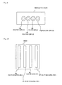
- FIGS. 11A and 11B show the relationship of reactive board 10 A mounted in mount block 1 , lens 5 , filter (LVF) 9 and CCD 4 .
- FIGS. 11A and 11B show the relationship of reactive board 10 A mounted in mount block 1 , lens 5 , filter (LVF) 9 and CCD 4 .
- Those parts in FIGS. 11A and 11B which are identical to those shown in FIGS. 8 and 9 are denoted by identical reference characters.
- FIG. 11B is a view as viewed in the direction of the arrow A in FIG. 11A .
- lens 5 comprises a cylindrical lens.
- cylindrical lens 5 forms the respective images of reaction surfaces 10 d - 10 g through filter (LVF) 9 as unchanged images on CCD 4 in the direction indicated by the arrow A in which reaction surfaces 10 d through 10 g are arrayed.
- cylindrical lens 5 forms the respective images of reaction surfaces 10 d - 10 g through filter (LVF) 9 as expanded images on CCD 4 in a direction perpendicular to the direction indicated by the arrow A in which reaction surfaces 10 d through 10 g are arrayed.
- the images expanded by cylindrical lens 5 fall on filter 9 .
- the wavelengths of the images (light rays) that pass through the filter 9 vary gradually from one end 9 b 1 to other end 9 b 2 of filter 9 .
- FIG. 12 shows CCD 4 on which the images of reaction surfaces 10 d through 10 g are formed by cylindrical lens 5 .
- Those parts shown in FIG. 12 which are identical to those shown in FIG. 10 are denoted by identical reference characters.
- image 10 d 1 of reaction surface 10 d is formed on color measuring area 4 d
- image 10 f 1 of reaction surface 10 f on color measuring area 4 f is formed on color measuring area 4 g
- image 10 g 1 of reaction surface 10 g on color measuring area 4 g is formed on color measuring area 4 d .
- image 10 d 1 of reaction surface 10 d that has passed through filter 9 represents the spectrum of the color of reaction surface 10 d .
- Image 10 e 1 of reaction surface 10 e that has passed through filter 9 represents the spectrum of the color of reaction surface 10 e .
- Image 10 f 1 of reaction surface 10 f that has passed through filter 9 represents the spectrum of the color of reaction surface 10 f .
- Image 10 g 1 of reaction surface 10 g that has passed through filter 9 represents the spectrum of the color of reaction surface 10 g.
- 256 photodetectors ⁇ of color measuring areas 4 d through 4 g detect light in different wavelengths, and color measuring areas 4 d through 4 g successively produce output signals depending on the intensities of the light detected by photodetectors ⁇ .
- input unit 2 receives a dark current measuring instruction, a light-emitting instruction and a binning instruction.
- input unit 2 When input unit 2 receives a dark current measuring instruction, input unit 2 supplies the dark current measuring instruction to spectrum detector 7 d 1 . When input unit 2 receives a light-emitting instruction, input unit 2 transmits the light-emitting instruction to light-emitting unit 3 and spectrum detector 7 d 1 .
- input unit 2 When input unit 2 receives a binning instruction, input unit 2 transmits the binning instruction to spectrum detector 7 d 1 and gas identifier 7 d 2 . Instead, a predetermined binning instruction may be set in controller 7 .
- Color information storage unit 7 a stores the names of colors in association with the spectrums of the colors.
- Spectrum database 7 b stores gas identifying information for identifying gases in association with color information about the colors of chemical reagents that have chemically reacted with gases identified by the gas identifying information.
- spectrum database 7 b stores color change information as color information.
- the color change information represents a change from the color of medium 103 before chemical reagent 101 flows into medium 103 to the color of medium 103 after chemical reagent 101 flows into medium 103 and chemically reacts therewith.
- spectrum database 7 b stores spectrum information as color change information.
- the spectrum information represents a spectrum showing a change of the color of medium 103 which is caused when a gas identified by gas identifying information and chemical reagent 101 chemically react with each other.
- spectrum database 7 b stores color information based on an output signal that is produced by CCD 4 when CCD 4 detects the color of chemical reagent 101 (medium 103 ) which has chemically reacted with a gas identified by gas identifying information.
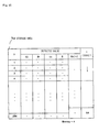
- FIG. 13 shows an example of data stored in spectrum database 7 b.
- spectrum database 7 b stores chemical reagent names 7 b 1 , gas identifying information 7 b 2 and color information 7 b 3 in association with each other.
- spectrum database 7 b for example, chemical reagent “A”, gas identifying information “a” and the spectrum of the color of chemical reagent “A” which has chemically reacted with a gas represented by gas identifying information “a” (specifically, a color change of medium 103 ) are associated with each other.
- spectrum detector 7 d 1 detects spectrums representing color changes of reaction surfaces 10 d through 10 g based on an output signal from CCD signal processor 6 .
- Memory 7 c stores the spectrums representing color changes of reaction surfaces 10 d through 10 g which are detected by spectrum detector 7 d 1 .
- FIG. 14 shows memory 7 c by way of example.
- memory 7 c has a plurality of storage areas 7 cd , 7 ce , 7 cf and 7 cg .
- Storage area 7 cd corresponds to reaction surface 10 d and color measuring area 4 d .
- Storage area 7 ce corresponds to reaction surface 10 e and color measuring area 4 e .
- Storage area 7 cf corresponds to reaction surface 10 f and color measuring area 4 f .
- Storage area 7 cg corresponds to reaction surface 10 g and color measuring area 4 g.
- Storage area 7 cd stores an output signal from color measuring area 4 d .
- Storage area 7 ce stores an output signal from color measuring area 4 e .
- Storage area 7 cf stores an output signal from color measuring area 4 f .
- Storage area 7 cg stores an output signal from color measuring area 4 g.
- FIG. 15 shows by way of example spectrums representative of color changes of reaction surface 10 d which are stored in storage area 7 cd . Spectrums representative of color changes of other reaction surfaces 7 ce , 7 cf and 7 cg are stored in other storage areas 7 ce , 7 cf and 7 cg.
- storage area 7 cd stores the names of the photodetectors ( ⁇ ) of color measuring area 4 d corresponding to reaction surface 10 d , output values S 0 , S 1 , SX thereof, relative intensity (spectral data) S, binning relative intensity (spectral data) Sb, and band value ⁇ , in association with each other.
- Output values S 0 , S 1 , SX, relative intensity S , binning relative intensity Sb, and band value ⁇ shown in FIG. 15 will be described below.
- a processing sequence with respect to reaction surface 10 d , color measuring area 4 d and storage area 7 cd only will be described below.
- a similar processing sequence is also performed with respect to other reaction surfaces, other color measuring areas, and other storage areas.
- input unit 2 When input unit 2 receives a dark current measuring instruction before chemical reagent 101 flows into medium 103 , input unit 2 supplies the dark current measuring instruction to spectrum detector 7 d 1 .
- spectrum detector 7 d 1 When spectrum detector 7 d 1 receives the dark current measuring instruction from input unit 2 , spectrum detector 7 d 1 measures output values S 0 ( ⁇ ) of the photodetectors ( ⁇ ) of color measuring area 4 d at the time light-emitting unit 3 is not energized. Spectrum detector 7 d 1 stores measured output values S 0 ( ⁇ ) into S 0 in storage area 7 cd.
- input unit 2 when input unit 2 receives a light-emitting instruction before chemical reagent 101 flows into medium 103 , input unit 2 supplies the light-emitting instruction to light-emitting unit 3 and spectrum detector 7 d 1 .
- light-emitting unit 3 When light-emitting unit 3 receives the light-emitting instruction from input unit 2 , light-emitting unit 3 applies light to reactive board 10 A.
- Reaction surface 10 d of reactive board 10 A reflects the light applied from light-emitting unit 3 .
- the reflected light takes on the color (reflected intensity) of reaction surface 10 d before chemical reagent 101 flows into reaction surface 10 d .
- the reflected light passes through filter 9 and is detected by photodetectors ⁇ of color measuring area 4 d . Therefore, an output signal from color measuring area 4 d represents the spectrum of the reflected light.
- spectrum detector 7 d 1 When spectrum detector 7 d 1 receives the light-emitting instruction after it has received the dark current measuring instruction, spectrum detector 7 d 1 measures output signals from photodetectors ⁇ of color measuring area 4 d , i.e., output values S 1 ( ⁇ ) representing the spectrum of the color of reaction surface 10 d before chemical reagent 101 flows into reaction surface 10 d . Spectrum detector 7 d 1 stores output values S 1 ( ⁇ ) into S 1 in storage area 7 cd.
- reaction surface 10 d When chemical reagent 101 flows into reaction surface 10 d , chemical reagent 101 chemically reacts with the gas to be identified which is held in contact with reaction surface 10 d.
- input unit 2 When input unit 2 receives a light-emitting instruction again after chemical reagent 101 has flowed into medium 103 , input unit 2 supplies the light-emitting instruction to light-emitting unit 3 and spectrum detector 7 d 1 .
- light-emitting unit 3 When light-emitting unit 3 receives the light-emitting instruction from input unit 2 , light-emitting unit 3 emits and applies light to reactive board 10 A.
- Reaction surface 10 d reflects the light applied from light-emitting unit 3 .
- the reflected light takes on the color (reflected intensity) of chemical reagent 101 which has chemically reacted with the gas to be identified.
- the reflected light takes on the color (reflected intensity) of reaction surface 10 d including chemical reagent 101 which has chemically reacted with the gas to be identified.
- the reflected light passes through filter 9 and is detected by photodetectors ⁇ of color measuring area 4 d . Therefore, an output signal from color measuring area 4 d represents the spectrum of the reflected light.
- spectrum detector 7 d 1 When spectrum detector 7 d 1 receives the light-emitting instruction again from input unit 2 , spectrum detector 7 d 1 measures output signals from photodetectors ⁇ of color measuring area 4 d , i.e., output values SX( ⁇ ) representing the spectrum of the color of reaction surface 10 d after chemical reagent 101 has flowed into reaction surface 10 d and has chemically reacted with the gas to be identified. Spectrum detector 7 d 1 stores output values SX( ⁇ ) into SX in storage area 7 cd.
- output values S 0 ( ⁇ ) and output values S 1 ( ⁇ ) are measured once, and measured output values S 0 ( ⁇ ) and measured output values S 1 ( ⁇ ) may be used in subsequent cycles. This makes it possible to minimize the process of calculating output values S( ⁇ ).
- Spectrum detector 7 d 1 stores output values S( ⁇ ) into S in storage area 7 cd.
- spectrum detector 7 d 1 After having stored output values S( ⁇ ) in storage area 7 cd , spectrum detector 7 d 1 calculates binning relative intensity (spectral data) Sb( ⁇ ) based on a binning instruction supplied from input unit 2 .
- spectrum detector 7 d 1 calculates binning relative intensity Sb( ⁇ ) based on a cluster of four output values S( ⁇ ).
- Spectrum detector 7 d 1 stores calculated binning relative intensities Sb( ⁇ ) into Sb( ⁇ ) in storage area 7 cd . Thereafter, spectrum detector 7 d 1 supplies binning relative intensities Sb( ⁇ ) to gas identifier 7 d 2 .
- spectrum detector 7 d 1 When spectrum detector 7 d 1 receives the binning instruction from input unit 2 , spectrum detector 7 d 1 calculates band ( ⁇ ) based on the binning instruction, and stores calculated band ( ⁇ ) into ⁇ in storage area 7 cd.
- Gas identifier 7 d 2 identifies spectrum information representing a spectrum which is most similar to the spectrum representing the color change of reaction surface 10 d detected by spectrum detector 7 d 1 , from the spectrum information 7 b 3 stored in spectrum database 7 b.
- gas identifier 7 d 2 identifies spectrum information which satisfies the two conditions 1 and 2 described below from spectrum information 7 b 3 stored in spectrum database 7 b.
- Condition 1 spectrum information having a spectrum waveform which is most similar to the waveform of the spectrum that represents the color change of the reaction surface.
- Condition 2 spectrum information having a spectrum waveform whose coincidence with the waveform of the spectrum that represents the color change of the reaction surface is equal to or greater than a predetermined value.
- gas identifier 7 d 2 performs the following process:
- Gas identifier 7 d 2 hypothetically places spectrum Sb( ⁇ ) that represents the color change of the reaction surface which is detected by spectrum detector 7 d 1 , in a multidimensional space having coordinates A.
- spectrum Sb( ⁇ ) is indicated as a vector in the multidimensional space.
- Gas identifier 7 d 2 processes each of the spectrum information stored in spectrum database 7 b based on the binning instruction supplied from input unit 2 to equalize the number of bands of each of the spectrum information to the number of bands of spectrum Sb( ⁇ ).
- gas identifier 7 d 2 brings the spectrum information of gases identified by gas identifying information 7 b 2 into clusters of four items of spectrum information to equalize the number of bands of each of the spectrum information stored in spectrum database 7 b to the number of bands of spectrum Sb( ⁇ ).
- Gas identifier 7 d 2 hypothetically places each of the spectrum information which has the same number of bands as the number of bands of spectrum Sb( ⁇ ), in the multidimensional space having coordinates ⁇ , as with spectrum Sb( ⁇ ). Thus, each of the spectrum information is indicated as a vector in the multidimensional space.
- Gas identifier 7 d 2 calculates the inner product of spectrum Sb( ⁇ ) and each of the spectrum information. Based on the calculated inner product, gas identifier 7 d 2 selects the spectrum information whose angle formed with respect to spectrum Sb( ⁇ ) is the smallest. This process is known in the art as spectral angle mapper (SAM).
- SAM spectral angle mapper
- the angle formed between the spectrum information and spectrum Sb( ⁇ ) is smaller as their spectral waveforms are closer to each other. Stated otherwise, the angle formed between the spectrum information and spectrum Sb( ⁇ ) is representative of the degree of coincidence between the spectrum information and spectrum Sb( ⁇ ).
- gas identifier 7 d 2 determines whether or not the angle between spectrum Sb( ⁇ ) and the selected spectrum information is equal to or smaller than a predetermined angle.
- gas identifier 7 d 2 identifies the selected spectrum information as spectrum information representative of spectrum Sb( ⁇ ).
- Gas identifier 7 d 2 reads gas identifying information 7 b 2 associated with the identified gas information from spectrum database 7 b.
- Gas identifier 7 d 2 outputs read gas identifying information 7 b 2 as gas identifying information representing the gas to be identified to display unit 8 .
- gas identifying device 1000 a Operation of gas identifying device 1000 a according to the first embodiment will be described below.
- FIG. 16 is a flowchart of an operation sequence of gas identifying device 1000 a . Operation of gas identifying device 1000 a will be described below with reference to FIG. 16 .
- the binning instruction is not limited to “binning 4 ”, but may be of any of binning values.
- step 1601 is executed.
- step 1601 the following process is performed:
- Input unit 2 supplies the dark current measuring instruction to spectrum detector 7 d 1 .
- spectrum detector 7 d 1 When spectrum detector 7 d 1 receives the dark current measuring instruction, spectrum detector 7 d 1 measures output values S 0 ( ⁇ ) of photodetectors ⁇ of color measuring areas 4 d through 4 g when light-emitting unit 3 does not emit light.
- Spectrum detector 7 d 1 stores measured output values S 0 ( ⁇ ) into S 0 in storage areas 7 cd , 7 ce , 7 cf and 7 cg (memory 7 c ) which correspond respectively to color measuring areas 4 d through 4 g.
- step 1601 The process in step 1601 is now finished.
- step 1602 is executed.
- step 1602 the following process is performed:
- Input unit 2 supplies the light-emitting instruction to light-emitting unit 3 and spectrum detector 7 d 1 .
- light-emitting unit 3 When light-emitting unit 3 receives the light-emitting instruction, light-emitting unit 3 applies light to reactive board 10 A.
- Reaction surfaces 10 d through 10 g of reactive board 10 A reflect the light applied from light-emitting unit 3 .
- the reflected light takes on the colors (reflected intensities) of reaction surfaces 10 d through 10 g before chemical reagents 101 flow into reaction surfaces 10 d through 10 g .
- the reflected light passes through filter 9 and is detected by photodetectors ⁇ of color measuring areas 4 d through 4 g . Therefore, output signals from color measuring areas 4 d through 4 g represent the spectrums of the reflected light which correspond to color measuring areas 4 d through 4 g.
- spectrum detector 7 d 1 When spectrum detector 7 d 1 receives the light-emitting instruction after it has received the dark current measuring instruction, spectrum detector 7 d 1 measures output signals from photodetectors ⁇ of color measuring areas 4 d through 4 g , i.e., output values S 1 ( ⁇ ) representing the spectrums of the colors of reaction surfaces 10 d through 10 g before chemical reagents 101 flow into reaction surfaces 10 d through 10 g .
- Spectrum detector 7 d 1 stores output values S 1 ( ⁇ ) into S 1 in storage areas 7 cd through 7 cg (memory 7 c ) which correspond to color measuring areas 4 d through 4 g.
- step 1602 The process in step 1602 is now finished.
- reaction surfaces 10 d through 10 g When ampules 102 are crushed, chemical reagents 101 contained in ampules 102 are discharged and flow into reaction surfaces 10 d through 10 g . When chemical reagents 101 flow into reaction surfaces 10 d through 10 g , they chemically react the gas to be identified which is held in contact with mediums 103 .
- step 1603 is executed.
- step 1603 the following process is performed:
- Input unit 2 supplies the light-emitting instruction to light-emitting unit 3 and spectrum detector 7 d 1 .
- light-emitting unit 3 When light-emitting unit 3 receives the light-emitting instruction, light-emitting unit 3 applies light to reactive board 10 A.
- Reaction surfaces 10 d through 10 g of reactive board 10 A reflect the light applied from light-emitting unit 3 .
- the reflected light takes on the colors (reflected intensities) of chemical reagents 101 which have chemically reacted with the gas to be identified.
- the reflected light takes on the colors of reaction surfaces 10 d through 10 g containing chemical reagents 101 which have chemically reacted with the gas to be identified.
- output signals from color measuring areas 4 d through 4 g represent the spectrums of the reflected light from reactive surfaces 10 d through 10 g which correspond to color measuring areas 4 d through 4 g.
- spectrum detector 7 d 1 When spectrum detector 7 d 1 receives the light-emitting instruction again from input unit 2 , spectrum detector 7 d 1 measures output signals from photodetectors ⁇ of color measuring areas 4 d through 4 g , i.e., output values SX( ⁇ ) representing the spectrums of the colors of reaction surfaces 10 d through 10 g after chemical reagents 101 have flowed into reaction surfaces 10 d through 10 g .
- Spectrum detector 7 d 1 stores output values SX( ⁇ ) into SX in storage areas 7 cd through 7 cg (memory 7 c ) which correspond to color measuring areas 4 d through 4 g.
- step 1603 The process in step 1603 is now finished.
- spectrum detector 7 d 1 executes step 1604 .
- Spectrum detector 7 d 1 stores calculated relative intensities S( ⁇ ) into S in storage areas 7 cd through 7 cg (memory 7 c ) corresponding to relative intensities S( ⁇ ). After having stored calculated relative intensities S( ⁇ ) into memory 7 c , spectrum detector 7 d 1 executes step 1605 .
- step 1605 spectrum detector 7 d 1 calculates binning relative intensities (spectral data) Sb( ⁇ ) with respect to the output values of color measuring areas 4 d through 4 g which are stored in storage areas 7 cd through 7 cg , based on a binning instruction supplied from input unit 2 .
- spectrum detector 7 d 1 calculates binning relative intensities Sb( ⁇ ) for respective clusters of four relative intensities S( ⁇ ).
- Spectrum detector 7 d 1 stores calculated binning relative intensities Sb( ⁇ ) into Sb( ⁇ ) in storage areas 7 cd through 7 cg corresponding to relative intensities S( ⁇ ). Thereafter, spectrum detector 7 d 1 supplies binning relative intensities Sb( ⁇ ) to gas identifier 7 d 2 .
- gas identifier 7 d 2 When gas identifier 7 d 2 receives binning relative intensities Sb( ⁇ ), gas identifier 7 d 2 executes steps 1606 and 1607 using SAM.
- gas identifier 7 d 2 identifies the spectrum information which satisfies two conditions 1 and 2 described below from spectrum information 7 b 3 stored in spectrum database 7 b , with respect to respective output values of color measuring areas 4 d through 4 g which are stored in respective storage areas 7 cd through 7 cg.
- Condition 1 spectrum information having a spectrum waveform which is most similar to the waveform of the spectrum that represents the color change of the reaction surface which is detected by spectrum detector 7 d 1 .
- Condition 2 spectrum information having a spectrum waveform whose coincidence with the waveform of the spectrum that represents the color change of the reaction surface is equal to or greater than a predetermined value.
- gas identifier 7 d 2 performs the following process:
- Gas identifier 7 d 2 executes step 1606 .
- gas identifier 7 d 2 performs the following process on each of the data of color measuring areas 4 d through 4 g:
- Gas identifier 7 d 2 hypothetically places spectrum Sb( ⁇ ) that represents the color change of the reaction surface which is detected by spectrum detector 7 d 1 , in a multidimensional space having coordinates ⁇ .
- Gas identifier 7 d 2 processes each of the spectrum information stored in spectrum database 7 b based on the binning instruction supplied from input unit 2 to equalize the number of bands of each of the spectrum information to the number of bands of spectrum Sb( ⁇ ).
- gas identifier 7 d 2 brings the spectrum information of gases identified by gas identifying information 7 b 2 into clusters of four items of spectrum information to equalize the number of bands of each of the spectrum information stored in spectrum database 7 b to the number of bands of spectrum Sb( ⁇ ).
- Gas identifier 7 d 2 hypothetically places each of the spectrum information which has the same number of bands as the number of bands of spectrum Sb( ⁇ ), in the multidimensional space having coordinates ⁇ , as with spectrum Sb( ⁇ ).
- gas identifier 7 d 2 executes step 1607 .
- gas identifier 7 d 2 calculates the inner product of spectrum Sb( ⁇ ) and each of the spectrum information. Based on the calculated inner product, gas identifier 7 d 2 selects the spectrum information whose angle formed with respect to spectrum Sb( ⁇ ) is the smallest.
- gas identifier 7 d 2 determines whether or not the angle between spectrum Sb( ⁇ ) and the selected spectrum information is equal to or smaller than a predetermined angle.
- gas identifier 7 d 2 identifies the selected spectrum information as spectrum information representative of spectrum Sb( ⁇ ).
- FIGS. 17 a through 17 c are illustrative of a method of identifying spectral information using SAM.
- DB 1 represents the spectral waveform of spectrum information associated with gas identifying information “a”
- DB 2 the spectral waveform of spectrum information associated with gas identifying information “b”
- DB 3 the spectral waveform of spectrum information associated with gas identifying information “c”.
- Sb 1 represents a measured spectrum.
- Measured spectrum Sb 1 has a waveform and an intensity similar to spectral waveform DB 2 .
- Sb 2 represents a measured spectrum.
- Measured spectrum Sb 2 has a waveform which is the same as spectral waveform DB 2 and has an intensity which is different from spectral waveform DB 2 .
- the degree of coincidence between spectral waveforms indicates the degree of coincidence between chemical reactions.
- the degree of coincidence between intensities does not necessarily indicate the degree of coincidence between chemical reactions because the intensity varies depending on the ambient temperature and moisture and the concentration of the gas in chemical reactions.
- spectrum information is identified according to SAM. Consequently, spectrum information corresponding to a measured spectrum is identified based on the degree of coincidence between spectral waveforms.
- FIG. 17 c is illustrative of an example in which DB 1 , DB 2 , DB 3 , Sb 1 and Sb 2 are placed in one multidimensional space.
- the angle between similar spectral waveforms Sb 1 and DB 2 is small, and the angle between similar spectral waveforms Sb 2 and DB 2 is also small.
- the first embodiment therefore, not only if spectral waveforms and intensities are similar to each other as shown in FIG. 17 a , but also if spectral waveforms are similar to each other, but spectral intensities are different from each other, it is possible to identify spectrum information corresponding to a measured spectrum.
- gas identifier 7 d 2 executes step 1608 .
- gas identifier 7 d 2 reads gas identifying information 7 b 2 associated with the identified spectrum information from spectrum database 7 b.
- Gas identifier 7 d 2 outputs read gas identifying information 7 b 2 to display unit 8 .
- step 1609 When display unit 8 receives gas identifying information 7 b 2 from gas identifier 7 d 2 , display unit 8 executes step 1609 .
- step 1609 display unit 8 displays gas identifying information 7 b 2 .
- processor 7 d identifies the color of each reaction surface based on the spectrum of the color of the reaction surface. Therefore, it is possible to identify the color of each reaction surface with high accuracy.
- processor 7 d identifies the gas to be identified which has chemically reacted with the chemical reagents on the reaction surfaces, based on the spectrum of the color of each reaction surface.
- spectrum database 7 b and processor 7 d may be modified as follows:
- Spectrum database 7 b stores gas identifying information and absorption lines obtained from the spectrums of the colors of chemical reagents 101 which have chemically reacted with gases identified by the gas identifying information, in association with each other.
- Processor 7 d identifies the absorption line of a substance that is generated by the chemical reaction between a gas to be identified and chemical reagent 101 , based on the color detected in the color measuring area. Processor 7 d identifies an absorption line closest to the absorption line from absorption lines stored in spectrum database 7 b . Processor 7 d reads the gas identifying information associated with the identified absorption line as the gas identifying information representative of the gas to be identified, from spectrum database 7 b.
- Color information may be stored in spectrum database 7 b as follows:
- the user introduces a plurality of chemical reagents into mediums 103 held in contact with a given gas in a predetermined sequence. Then, the user successively detects changes in the colors of mediums 103 using color measuring areas. Spectrum database 7 b stores the color changes that are successively detected by the color measuring areas, as color information corresponding to the given gas (identifying information of the given gas).
- Controller 7 identifies a gas to be identified as follows:
- the user introduces a plurality of chemical reagents into reaction surfaces held in contact with a gas to be identified in the predetermined sequence, and successively detects changes in the colors of reaction surfaces using the color measuring areas.
- processor 7 d Each time a color detecting area detects a change in the color of the reaction surface, processor 7 d compares the detected color change with the color information stored in spectrum database 7 b , and identifies the color information representing a color that is most similar to the color detected by the color detecting area, from the color information stored in spectrum database 7 b . Processor 7 d then reads the gas identifying information associated with the identified color information from spectrum database 7 b.
- CCD 4 detects light emitted from light-emitting unit 3 and transmitted through the reaction surfaces, rather than detecting light emitted from light-emitting unit 3 and reflected by the reaction surfaces.
- the gas identifying device may be incorporated in the reader device disclosed in U.S. Pat. No. 6,228,657B1.
- Colors may be identified using SAM.
- a gas identifying device according to a second embodiment of the present invention will be described below.
- FIG. 18 shows in block form gas identifying device 1000 b according to the second embodiment.
- Gas identifying device 1000 b identifies the colors of respective reaction surfaces and a gas to be identified, based on the ratio of components R, G, B of the colors of the reaction surfaces.
- Those parts of gas identifying device 1000 b shown in FIG. 18 which are identical to those shown in FIG. 1 are denoted by identical reference characters.
- gas identifying device 1000 b comprises mount block 1 , input unit 2 , light-emitting unit 3 , color CCD 4 A, lens 5 , CCD signal processor 6 , controller 7 and display unit 8 .
- Controller 7 comprises color information storage unit 7 a , gas information storage unit 7 b , memory 7 c and processor 7 d.
- Reactive board 10 B which is an example of a board to be measured, is mounted in mount block 1 .
- FIG. 19 shows reactive board 10 B and color CCD 4 A.
- reactive board 10 B has a matrix of reaction surfaces (surfaces to be measured) 10 h , 10 i , 10 j and 10 k . Each of reaction surfaces 10 h through 10 k is disposed in a predetermined position on reactive board 10 B. In FIG. 19 , the ampules are omitted from illustration.
- Color CCD 4 A has a plurality of color measuring areas 4 h , 4 i , 4 j and 4 k corresponding respectively to reaction surfaces 10 h , 10 i , 10 j and 10 k of reactive board 10 B mounted in mount block 1 .
- color measuring area 4 h corresponds to reaction surface 10 h
- color measuring area 4 i to reaction surface 10 i corresponds to reaction surface 10 i
- color measuring area 4 k to reaction surface 10 k .
- Each of color measuring areas 4 h through 4 k comprises an array of photodetectors.
- lens 5 forms image 10 h 1 of reaction surface 10 h on color measuring area 4 h , image 10 i 1 of reaction surface 10 i on color measuring area 4 i , image 10 j 1 of reaction surface 10 j on color measuring area 4 j , and image 10 k 1 of reaction surface 10 k on color measuring area 4 k at the same time.
- an output signal from color measuring area 4 h varies depending on the color of reaction surface 10 h
- an output signal from color measuring area 4 i varies depending on the color of reaction surface 10 i
- an output signal from color measuring area 4 j varies depending on the color of reaction surface 10 j
- an output signal from color measuring area 4 k varies depending on the color of reaction surface 10 k.
- color information storage unit 7 a stores a chromaticity diagram.
- the chromaticity diagram has x and y coordinates.
- the x coordinates represent values R/(R+ G +B), and the y coordinates values G/(R+G+B).
- R represents a red component of color
- G a green component of color
- B a blue component of color.
- the chromaticity diagram is peculiar to the present invention. In other words, the chromaticity diagram may be a relative chromaticity diagram.
- Gas information storage unit 7 b stores gas identifying information for identifying gases and chromaticity diagram coordinates of the colors of chemical reagents that have chemically reacted with gases identified by the gas identifying information, in association with each other.
- Memory 7 c stores the output signals from color measuring areas 4 h through 4 k.
- FIG. 20 shows memory 7 c by way of example. As shown in FIG. 20 , memory 7 c has a plurality of storage areas 7 ch , 7 ci , 7 cj and 7 ck.
- processor 7 d processes an output signal from CCD 4 A with respect to each of color measuring areas 4 h through 4 k.
- processor 7 d stores the output signal from color measuring area 4 h into storage area 7 ch , the output signal from color measuring area 4 i into storage area 7 ci , the output signal from color measuring area 4 j into storage area 7 cj , and the output signal from color measuring area 4 k into storage area 7 ck.
- Processor 7 d integrates output values of components R, G, B of color measuring area 4 h respectively. It is assumed that an integrated value of output values of component R is represented by R 1 , an integrated value of output values of component G by G 1 , and an integrated value of output values of component B by B 1 .
- processor 7 d identifies coordinates closest to the identified x and y coordinates of the chromaticity diagram, from the coordinates stored in gas information storage unit 7 b .
- Processor 7 d reads the gas identifying information associated with the identified coordinates from gas information storage unit 7 b.
- processor 7 d controls display unit 8 to display the color of reaction surface 10 h and the gas identifying information.
- Processor 7 d also processes output signals from other color measuring areas 4 i , 4 j and 4 k in the same manner as with color measuring area 4 h.
- gas identifying device 1000 b Operation of gas identifying device 1000 b according to the second embodiment will be described below.
- Gas identifying device 1000 b operates essentially according to the flowchart shown in FIG. 7 .
- steps 703 and 704 based on a feature of the second embodiment will mainly be described below.
- processor 7 d integrates respective output values of components R, G and B of color measuring area 4 h , thereby calculating integrated values R 1 , G 1 and B 1 .
- processor 7 d executes step 704 .
- processor 7 d identifies the coordinates closest to the coordinates obtained as representing the color of reaction surface 10 h from the coordinates stored in gas information storage unit 7 b .
- Processor 7 d reads the gas identifying information associated with the identified coordinates from gas information storage unit 7 b .
- Processor 7 d also processes output signals from other color measuring areas 4 i , 4 j and 4 k in the same manner as with color measuring area 4 h.
- processor 7 d identifies the colors of the reaction surfaces based on components R, G and B of the colors of the reaction surfaces. Therefore, the colors of the reaction surfaces can be identified with high accuracy.
- processor 7 d identifies a gas to be identified which has chemically reacted with the chemical reagents on the reaction surfaces, based on components R, G, B of the colors of the reaction surfaces. Therefore, the gas to be identified can be identified with high accuracy.
Landscapes
- Physics & Mathematics (AREA)
- Spectroscopy & Molecular Physics (AREA)
- General Physics & Mathematics (AREA)
- Chemical & Material Sciences (AREA)
- General Health & Medical Sciences (AREA)
- Life Sciences & Earth Sciences (AREA)
- Analytical Chemistry (AREA)
- Biochemistry (AREA)
- Health & Medical Sciences (AREA)
- Immunology (AREA)
- Pathology (AREA)
- Engineering & Computer Science (AREA)
- Chemical Kinetics & Catalysis (AREA)
- Plasma & Fusion (AREA)
- Investigating Or Analysing Materials By The Use Of Chemical Reactions (AREA)
- Spectrometry And Color Measurement (AREA)
Applications Claiming Priority (2)
| Application Number | Priority Date | Filing Date | Title |
|---|---|---|---|
| JP2006078809A JP2007255995A (ja) | 2006-03-22 | 2006-03-22 | 色識別装置およびガス特定装置 |
| JP2006-078809 | 2006-03-22 |
Publications (2)
| Publication Number | Publication Date |
|---|---|
| US20070222992A1 US20070222992A1 (en) | 2007-09-27 |
| US7746474B2 true US7746474B2 (en) | 2010-06-29 |
Family
ID=38533024
Family Applications (1)
| Application Number | Title | Priority Date | Filing Date |
|---|---|---|---|
| US11/723,656 Expired - Fee Related US7746474B2 (en) | 2006-03-22 | 2007-03-21 | Color identifying device for identifying colors of reaction surfaces produced by chemical reaction and gas identifying device |
Country Status (2)
| Country | Link |
|---|---|
| US (1) | US7746474B2 (ja) |
| JP (1) | JP2007255995A (ja) |
Cited By (3)
| Publication number | Priority date | Publication date | Assignee | Title |
|---|---|---|---|---|
| US20080267493A1 (en) * | 2007-01-26 | 2008-10-30 | Nec Corporation | Color identifying apparatus and color identifying method |
| US20090111191A1 (en) * | 2007-10-24 | 2009-04-30 | Honeywell International Inc. | Gas analyzer cassette system |
| US20150241345A1 (en) * | 2014-02-27 | 2015-08-27 | Honeywell International Inc. | Multi-point Gas Detector |
Families Citing this family (7)
| Publication number | Priority date | Publication date | Assignee | Title |
|---|---|---|---|---|
| JP5066137B2 (ja) * | 2009-06-05 | 2012-11-07 | 日本電信電話株式会社 | ガス濃度測定装置及びガス濃度測定方法 |
| JP2012150096A (ja) * | 2011-01-20 | 2012-08-09 | Middleland Sensing Technology Inc | 試験紙自動判定方法及びシステム |
| US9061099B2 (en) | 2011-04-29 | 2015-06-23 | Medtronic, Inc. | Cardiovascular monitoring for fluid removal processes |
| US20180073989A1 (en) * | 2016-09-09 | 2018-03-15 | Medtronic, Inc. | Fluid sensor card |
| US11013843B2 (en) | 2016-09-09 | 2021-05-25 | Medtronic, Inc. | Peritoneal dialysis fluid testing system |
| CN110553738A (zh) * | 2019-08-05 | 2019-12-10 | 华南理工大学 | 基于颜色传感器的化学反应进程检测方法及系统 |
| US11850344B2 (en) | 2021-08-11 | 2023-12-26 | Mozarc Medical Us Llc | Gas bubble sensor |
Citations (8)
| Publication number | Priority date | Publication date | Assignee | Title |
|---|---|---|---|---|
| US3756725A (en) * | 1970-10-12 | 1973-09-04 | Harris Intertype Corp | Measurement and control of ink density |
| US4681454A (en) * | 1984-02-07 | 1987-07-21 | N.V. Optische Industrie "De Oude Delft" | Device for detecting differences in color |
| US5091642A (en) * | 1990-05-11 | 1992-02-25 | Mda Scientific, Inc. | Colorimetric detection apparatus |
| US5706083A (en) * | 1995-12-21 | 1998-01-06 | Shimadzu Corporation | Spectrophotometer and its application to a colorimeter |
| US6228657B1 (en) | 1998-09-29 | 2001-05-08 | The United States Of America As Represented By The Secretary Of The Army | Environmental material ticket reader and airborne hazard detection system |
| US20060008919A1 (en) * | 2004-07-09 | 2006-01-12 | Boay Yoke P | Method and apparatus for detecting gas/radiation that employs color change detection mechanism |
| US7277019B2 (en) * | 2004-10-29 | 2007-10-02 | Motorola, Inc. | Universal colorimetric imaging array device |
| US7499154B2 (en) * | 2003-06-03 | 2009-03-03 | Siemens Healthcare Diagnostics Inc. | Readhead for optical inspection apparatus |
Family Cites Families (4)
| Publication number | Priority date | Publication date | Assignee | Title |
|---|---|---|---|---|
| JP3522851B2 (ja) * | 1994-09-20 | 2004-04-26 | 高砂熱学工業株式会社 | 検出方法 |
| JP3709429B2 (ja) * | 1996-07-15 | 2005-10-26 | 栄研化学株式会社 | 試験片分析装置及び試験片を用いる分析方法 |
| JP2000121562A (ja) * | 1998-10-15 | 2000-04-28 | Ebisu Denki Kk | 呈色物定量装置および呈色物定量用記憶媒体 |
| JP2006047305A (ja) * | 2005-07-08 | 2006-02-16 | Nec Corp | ガス特定装置、ガス特定方法、ガス対処支援システムおよびガス対処支援方法 |
-
2006
- 2006-03-22 JP JP2006078809A patent/JP2007255995A/ja active Pending
-
2007
- 2007-03-21 US US11/723,656 patent/US7746474B2/en not_active Expired - Fee Related
Patent Citations (8)
| Publication number | Priority date | Publication date | Assignee | Title |
|---|---|---|---|---|
| US3756725A (en) * | 1970-10-12 | 1973-09-04 | Harris Intertype Corp | Measurement and control of ink density |
| US4681454A (en) * | 1984-02-07 | 1987-07-21 | N.V. Optische Industrie "De Oude Delft" | Device for detecting differences in color |
| US5091642A (en) * | 1990-05-11 | 1992-02-25 | Mda Scientific, Inc. | Colorimetric detection apparatus |
| US5706083A (en) * | 1995-12-21 | 1998-01-06 | Shimadzu Corporation | Spectrophotometer and its application to a colorimeter |
| US6228657B1 (en) | 1998-09-29 | 2001-05-08 | The United States Of America As Represented By The Secretary Of The Army | Environmental material ticket reader and airborne hazard detection system |
| US7499154B2 (en) * | 2003-06-03 | 2009-03-03 | Siemens Healthcare Diagnostics Inc. | Readhead for optical inspection apparatus |
| US20060008919A1 (en) * | 2004-07-09 | 2006-01-12 | Boay Yoke P | Method and apparatus for detecting gas/radiation that employs color change detection mechanism |
| US7277019B2 (en) * | 2004-10-29 | 2007-10-02 | Motorola, Inc. | Universal colorimetric imaging array device |
Cited By (6)
| Publication number | Priority date | Publication date | Assignee | Title |
|---|---|---|---|---|
| US20080267493A1 (en) * | 2007-01-26 | 2008-10-30 | Nec Corporation | Color identifying apparatus and color identifying method |
| US8094929B2 (en) * | 2007-01-26 | 2012-01-10 | Nec Corporation | Color identifying apparatus and color identifying method |
| US20090111191A1 (en) * | 2007-10-24 | 2009-04-30 | Honeywell International Inc. | Gas analyzer cassette system |
| US8128873B2 (en) * | 2007-10-24 | 2012-03-06 | Honeywell International Inc. | Gas analyzer cassette system |
| US20150241345A1 (en) * | 2014-02-27 | 2015-08-27 | Honeywell International Inc. | Multi-point Gas Detector |
| US9651532B2 (en) * | 2014-02-27 | 2017-05-16 | Honeywell International, Inc. | Multi-point gas detector |
Also Published As
| Publication number | Publication date |
|---|---|
| US20070222992A1 (en) | 2007-09-27 |
| JP2007255995A (ja) | 2007-10-04 |
Similar Documents
| Publication | Publication Date | Title |
|---|---|---|
| US7746474B2 (en) | Color identifying device for identifying colors of reaction surfaces produced by chemical reaction and gas identifying device | |
| US8144322B2 (en) | Spectral characteristic measuring apparatus, method for calibrating spectral characteristic measuring apparatus, and spectral characteristic measuring system | |
| EP1830174B1 (en) | Multi-channel fluorescence sample analyzer | |
| US7944564B2 (en) | Device and method for acquiring information on objective substance to be detected by detecting a change of wavelength characteristics on the optical transmittance | |
| JPH10508940A (ja) | 色特性の測定及び解析用を主とするスペクトル放射を測定・解析する装置及び方法 | |
| US9316581B2 (en) | Method, apparatus, and article to facilitate evaluation of substances using electromagnetic energy | |
| US10145795B2 (en) | Light detection apparatus | |
| US20080266563A1 (en) | Measuring color using color filter arrays | |
| CN106796146B (zh) | 确定入射辐射的频谱发射特性 | |
| EA008454B1 (ru) | Способ и устройство для определения подлинности документов и товаров | |
| JP5812178B2 (ja) | 光学特性測定装置 | |
| JP2010127739A (ja) | 分光感度特性測定装置および分光感度特性測定方法 | |
| KR20180021691A (ko) | 협대역 광 센서를 이용하여 다수의 특정 파장 영역에서 변형 생성을 측정하는 것에 의한 가스 식별 | |
| US10883878B2 (en) | Fluorescence measurement of samples | |
| US8094929B2 (en) | Color identifying apparatus and color identifying method | |
| US8470248B2 (en) | Gas identifying apparatus, gas identifying method gas handling assisting system and gas handling assisting method for identifying gas based on color of reaction surface produced by chemical reaction | |
| JP6038445B2 (ja) | 自動分析装置 | |
| EP3921627B1 (en) | Method of analyzing samples, analyzing device and computer program | |
| CN112611726A (zh) | 一种分子特征吸收光谱测量装置及方法 | |
| US20240151638A1 (en) | Spectrum measurement apparatus and spectrum measurement method | |
| CN114674789A (zh) | 一种基于手机的生物检测方法及装置 | |
| JP2020005053A (ja) | イメージセンサの分光感度測定方法、分光感度測定装置の検査方法及び分光感度測定装置 | |
| US20090155919A1 (en) | High throughput drug screening method | |
| WO2023241076A1 (zh) | 一种高光谱测序方法、系统和基因测序仪 | |
| JPS62137527A (ja) | 分光分布検査装置 |
Legal Events
| Date | Code | Title | Description |
|---|---|---|---|
| AS | Assignment |
Owner name: NEC CORPORATION,JAPAN Free format text: ASSIGNMENT OF ASSIGNORS INTEREST;ASSIGNOR:ODA, NAOKI;REEL/FRAME:019126/0994 Effective date: 20070301 Owner name: NEC CORPORATION, JAPAN Free format text: ASSIGNMENT OF ASSIGNORS INTEREST;ASSIGNOR:ODA, NAOKI;REEL/FRAME:019126/0994 Effective date: 20070301 |
|
| STCF | Information on status: patent grant |
Free format text: PATENTED CASE |
|
| FPAY | Fee payment |
Year of fee payment: 4 |
|
| FEPP | Fee payment procedure |
Free format text: MAINTENANCE FEE REMINDER MAILED (ORIGINAL EVENT CODE: REM.) |
|
| LAPS | Lapse for failure to pay maintenance fees |
Free format text: PATENT EXPIRED FOR FAILURE TO PAY MAINTENANCE FEES (ORIGINAL EVENT CODE: EXP.); ENTITY STATUS OF PATENT OWNER: LARGE ENTITY |
|
| STCH | Information on status: patent discontinuation |
Free format text: PATENT EXPIRED DUE TO NONPAYMENT OF MAINTENANCE FEES UNDER 37 CFR 1.362 |
|
| FP | Lapsed due to failure to pay maintenance fee |
Effective date: 20220629 |