US7735885B2 - Rear bumper assembly and tail trim cover for vehicle - Google Patents
Rear bumper assembly and tail trim cover for vehicle Download PDFInfo
- Publication number
- US7735885B2 US7735885B2 US12/336,201 US33620108A US7735885B2 US 7735885 B2 US7735885 B2 US 7735885B2 US 33620108 A US33620108 A US 33620108A US 7735885 B2 US7735885 B2 US 7735885B2
- Authority
- US
- United States
- Prior art keywords
- tail trim
- cover
- rear bumper
- main
- bumper assembly
- Prior art date
- Legal status (The legal status is an assumption and is not a legal conclusion. Google has not performed a legal analysis and makes no representation as to the accuracy of the status listed.)
- Active
Links
- 230000003247 decreasing effect Effects 0.000 claims abstract description 9
- 238000003466 welding Methods 0.000 claims description 8
- 239000000945 filler Substances 0.000 claims description 6
- 239000000463 material Substances 0.000 description 4
- 238000012986 modification Methods 0.000 description 3
- 230000004048 modification Effects 0.000 description 3
- 238000005452 bending Methods 0.000 description 2
- 238000000034 method Methods 0.000 description 2
- 230000000712 assembly Effects 0.000 description 1
- 238000000429 assembly Methods 0.000 description 1
- 230000015572 biosynthetic process Effects 0.000 description 1
- 239000007795 chemical reaction product Substances 0.000 description 1
- 238000003780 insertion Methods 0.000 description 1
- 230000037431 insertion Effects 0.000 description 1
- 238000004519 manufacturing process Methods 0.000 description 1
Images


Classifications
-
- B—PERFORMING OPERATIONS; TRANSPORTING
- B60—VEHICLES IN GENERAL
- B60K—ARRANGEMENT OR MOUNTING OF PROPULSION UNITS OR OF TRANSMISSIONS IN VEHICLES; ARRANGEMENT OR MOUNTING OF PLURAL DIVERSE PRIME-MOVERS IN VEHICLES; AUXILIARY DRIVES FOR VEHICLES; INSTRUMENTATION OR DASHBOARDS FOR VEHICLES; ARRANGEMENTS IN CONNECTION WITH COOLING, AIR INTAKE, GAS EXHAUST OR FUEL SUPPLY OF PROPULSION UNITS IN VEHICLES
- B60K13/00—Arrangement in connection with combustion air intake or gas exhaust of propulsion units
- B60K13/04—Arrangement in connection with combustion air intake or gas exhaust of propulsion units concerning exhaust
-
- B—PERFORMING OPERATIONS; TRANSPORTING
- B60—VEHICLES IN GENERAL
- B60R—VEHICLES, VEHICLE FITTINGS, OR VEHICLE PARTS, NOT OTHERWISE PROVIDED FOR
- B60R19/00—Wheel guards; Radiator guards, e.g. grilles; Obstruction removers; Fittings damping bouncing force in collisions
- B60R19/02—Bumpers, i.e. impact receiving or absorbing members for protecting vehicles or fending off blows from other vehicles or objects
- B60R19/023—Details
-
- B—PERFORMING OPERATIONS; TRANSPORTING
- B62—LAND VEHICLES FOR TRAVELLING OTHERWISE THAN ON RAILS
- B62D—MOTOR VEHICLES; TRAILERS
- B62D25/00—Superstructure or monocoque structure sub-units; Parts or details thereof not otherwise provided for
- B62D25/20—Floors or bottom sub-units
-
- F—MECHANICAL ENGINEERING; LIGHTING; HEATING; WEAPONS; BLASTING
- F01—MACHINES OR ENGINES IN GENERAL; ENGINE PLANTS IN GENERAL; STEAM ENGINES
- F01N—GAS-FLOW SILENCERS OR EXHAUST APPARATUS FOR MACHINES OR ENGINES IN GENERAL; GAS-FLOW SILENCERS OR EXHAUST APPARATUS FOR INTERNAL COMBUSTION ENGINES
- F01N13/00—Exhaust or silencing apparatus characterised by constructional features ; Exhaust or silencing apparatus, or parts thereof, having pertinent characteristics not provided for in, or of interest apart from, groups F01N1/00 - F01N5/00, F01N9/00, F01N11/00
- F01N13/08—Other arrangements or adaptations of exhaust conduits
-
- B—PERFORMING OPERATIONS; TRANSPORTING
- B60—VEHICLES IN GENERAL
- B60R—VEHICLES, VEHICLE FITTINGS, OR VEHICLE PARTS, NOT OTHERWISE PROVIDED FOR
- B60R19/00—Wheel guards; Radiator guards, e.g. grilles; Obstruction removers; Fittings damping bouncing force in collisions
- B60R19/02—Bumpers, i.e. impact receiving or absorbing members for protecting vehicles or fending off blows from other vehicles or objects
- B60R19/48—Bumpers, i.e. impact receiving or absorbing members for protecting vehicles or fending off blows from other vehicles or objects combined with, or convertible into, other devices or objects, e.g. bumpers combined with road brushes, bumpers convertible into beds
Definitions
- the present invention relates to a rear bumper assembly and a tail trim cover for a vehicle through which the tail pipe of a muffler is inserted.
- a tail trim is mounted to a rear bumper cover such that the tail pipe of a muffler can be installed through the tail trim.
- a tail trim 10 composed of a main tail trim 16 , a tail trim upper cover 12 and a tail trim lower cover 13 is assembled to a rear bumper cover 20 such that the tail trim 10 is matched to the exhaust hole of the rear bumper cover 20 .
- the tail trim 10 is fastened to the rear bumper cover 20 by way of separate mounting brackets 11 , and an insertion part 15 of the tail trim 10 , through which the tail pipe of a muffler is inserted, is fastened to the rear bumper cover 20 through a welded mounting bracket 14 .
- the manufacturing and material costs increase, and ease of assembly is degraded due to the addition of a welding process. Also, because welding parts are exposed to the outside, the outer appearance is likely to be deteriorated.
- the tail trim upper cover 12 and the tail trim lower cover 13 are locked in a surface matching type such that they are fitted around and then welded to the main tail trim 16 .
- a step or a gap (of about 5 mm) that is different from an original design comes at the distal end of the main tail trim 16 .
- Various aspects of the present invention provide for a rear bumper assembly and a tail trim cover for a vehicle, which can reduce rear seat noise including the noise generated due to vibration in the joint between a main tail trim and a rear bumper cover and flow-induced noise.
- An aspect of the present invention may be directed to a rear bumper assembly of a vehicle, including a rear bumper cover having an exhaust hole portion therein, a main tail trim mounted to the exhaust hole portion, and/or a tail trim cover coupled to the main tail trim, wherein bent portion defining a gradually decreasing diameter toward a longitudinal axis of the main tail trim may be formed in a joint region between the main tail trim and the tail trim cover.
- Locking flanges for locking the main tail trim to the rear bumper cover may be formed monolithically with the main tail trim.
- the tail trim cover may have an upper tail trim cover and a lower tail trim cover which may be coupled with each other. Spot welding portions to be spot-welded with each other may be protrusively formed on sides of the upper tail trim cover and the lower tail trim cover. Guide portion may be formed on the bent portion to cover the joint region between the main tail trim and the tail trim cover.
- Another aspect of the present invention is directed to a rear bumper assembly of a vehicle including a rear bumper cover having an exhaust hole portion extending in a forward direction of the vehicle, a main tail trim, a portion of which may be mounted to the exhaust hole portion, and/or a tail trim cover coupled to and enclosing outer circumference of tubular portion of the main tail trim, the tail trim including a bent portion to substantially continuously couple the main tail trim and the tail trim cover therebetween to allow an exhaust gas to flow smoothly therethrough.
- a gap filler may be filled between distal end of the tubular portion and the bending portion so as to increase a continuity between the main tail trim and the tail trim cover.
- the bent portion may define a gradually decreasing diameter toward a longitudinal axis of the main tail trim in a joint region of both the main tail trim and the tail trim cover.
- a locking flange for locking the main tail trim to the rear bumper cover may be formed monolithically on the main tail trim.
- the locking flange may include a dent portion protruding from the mail tail trim in a rear direction of the vehicle, and/or a locking hole placed at the dent portion wherein a fastening bolt may be locked therethrough.
- the tail trim cover may include an upper tail trim cover and a lower tail trim cover which may be coupled with each other. Spot welding portions to be spot-welded with each other may be protrusively formed on lateral sides of the upper tail trim cover and the lower tail trim cover respectively.
- the upper tail trim cover and the lower tail trim cover may be made monolithically to form a single body.
- a guide portion may be formed on the bent portion to cover inner circumference of an distal end of the tubular portion.
- the guide portion may be filleted so as to increase continuity between the main tail trim and the tail trim cover.
- a gap filler may be filled between the distal end of tubular portion and the bending portion so as to increase a continuity between the main tail trim and the tail trim cover.
- a passenger vehicle may include any of the above-described the bumper assemblies.
- the passenger vehicle may further include a guide portion formed on the bent portion to cover inner circumference of a distal end of the tubular portion.
- FIG. 1 is a view illustrating a tail trim which is mounted to a rear bumper cover according to the conventional art.
- FIG. 2 is a sectional view taken along the line A-A of FIG. 1 .
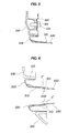
- FIG. 3 is a view illustrating an exemplary rear bumper assembly in accordance with the present invention.
- FIG. 4 is a sectional view taken along the line B-B of FIG. 3 .
- FIG. 5 is a sectional view illustrating the state in which a main tail trim is locked to a rear bumper cover in accordance the present invention.
- FIG. 6 is a sectional view illustrating an exemplary rear bumper assembly in accordance the present invention.
- a tail trim cover 200 having bent portions 211 curved toward the longitudinal axis of a tubular portion 310 is assembled around the outer surface of the tubular portion 310 of a main tail trim 300 .
- the tail trim cover 200 and the tubular portion 310 are coupled substantially continuous so that it is possible to prevent noise such as vibration noise and flow-induced noise from occurring in a joint region B′ between the tail trim cover 200 and the tubular portion 310 .
- a gap filler may be filled between the bent portions 211 and the tubular portion 310 to increase the continuity therebetween.
- locking flanges 320 for locking the main tail trim 300 to a rear bumper cover 100 are formed integrally with the main tail trim 300 so that material cost can be decreased and the ease of assembly is improved.
- a rear bumper assembly in accordance with various embodiments of the present invention has a structure in which the main tail trim 300 is mounted in an exhaust hole portion 110 of the rear bumper cover 100 and the tail trim cover 200 having the bent portions 211 is fitted around the main tail trim 300 .
- the main tail trim 300 has the tubular portion 310 which is formed on the center portion of the main tail trim 300 and extends toward the front of a vehicle (the rightward direction in FIG. 4 ).
- the tubular portion 310 is connected to and communicates with the tail trim cover 200 so that exhaust gas can be discharged via the tail pipe of a muffler through the tubular portion 310 .
- the tail trim cover 200 is fitted around the tubular portion 310 in such a way as to surround the outer surface of the tubular portion 310 .
- exhaust gas discharge noise or flow-induced noise is likely to be generated. This is because the distal end of the tubular portion 310 projects in the joint region B′ so that a step (a gap) is created.
- the bent portions 211 curved toward the longitudinal axis of a tubular portion 310 are formed in the tail trim cover 200 which is fitted around the outer surface of the tubular portion 310 .
- the bent portions 211 are formed such that the inner diameter of the tail trim cover 200 is decreased in the joint region B′. Accordingly, the exhaust gas guided through the tail pipe of the muffler can smoothly flow from the tail trim cover 200 to the tubular portion 310 through the bent portions 211 which are flush with the distal end of the tubular portion 310 .
- a gap filler may be embedded therebetween as set forth above. Due to this fact, rear seat noise including exhaust gas discharge noise, vibration noise and flow-induced noise is reduced, whereby the NVH (noise, vibration and harshness) performance of the vehicle can be improved.
- the locking flanges 320 to be locked to the exhaust hole portion 110 of the rear bumper cover 100 are formed adjacent to the outer edge of the main tail trim 300 .
- the locking flanges 320 are defined with locking holes 321 through which fastening bolts 120 are locked.
- the locking flanges 320 are formed integrally with the outer edge of the main tail trim 300 .
- the tail trim cover 200 is connected to and communicates with the tubular portion 310 of the main tail trim 300 and is supported by the rear bumper cover 100 by the medium of mounting brackets 400 .
- the tail pipe of the muffler, through which exhaust gas is discharged, is at least partially inserted into the tail trim cover 200 .
- the exhaust gas guided through the tail pipe of the muffler is discharged to the rear of the vehicle after passing through the tail trim cover 200 and the main tail trim 300 .
- the tail trim cover 200 is composed of an upper tail trim cover 210 and a lower tail trim cover 220 which are coupled with each other.
- the upper tail trim cover 210 and the lower tail trim cover 220 are fastened to each other by spot welding.
- spot welding portions 230 to be spot-welded with each other are protrusively formed on the sides of the upper tail trim cover 210 and the lower tail trim cover 220 .
- guide portions 240 are formed in the tail trim cover 200 to cover a joint region C′ between the tubular portion 310 and the tail trim cover 200 .
- the guide portion 240 is placed on the inner circumference of the tubular portion 310 and extends rearward (the leftward direction in FIG. 6 ) horizontally from the bent portions 211 of the tail trim cover 200 to prevent exhaust gas from being introduced into the joint region C′. Accordingly, exhaust gas does not leak through the joint region C′ and can smoothly flow from the tail trim cover 200 to the tubular portion 310 .
- the guide portion 240 may be filleted so as to increase continuity between the tail trim cover 200 and the tubular portion 310 .
- the structure of the joint between the main tail trim 300 and the tail trim cover 200 is modified so that it is possible to prevent noise such as vibration noise and flow-induced noise from being generated.
- the locking flanges 320 are formed integrally with the main tail trim 300 , the ease of assembly of the rear bumper cover 100 and the main tail trim 300 can be improved.
- the appearance of an end product can be improved and the assembly tolerances between the main tail trim and the tail trim cover can be elevated.
- the rear seat noise including exhaust gas-discharge noise, vibration noise and flow-induced noise generated in the joint can be reduced, and therefore, an NVH performance can be improved.
- a locking flange is formed integrally with the main tail trim, rigidity can be increased when assembling a rear bumper cover and the main tail trim with each other, material costs can be decreased, and ease of assembly can be improved.
Abstract
Description
Claims (17)
Applications Claiming Priority (2)
| Application Number | Priority Date | Filing Date | Title |
|---|---|---|---|
| KR10-2008-0026124 | 2008-03-21 | ||
| KR1020080026124A KR100946478B1 (en) | 2008-03-21 | 2008-03-21 | Rear bumper assembly and tail trim cover for vehicles |
Publications (2)
| Publication Number | Publication Date |
|---|---|
| US20090236868A1 US20090236868A1 (en) | 2009-09-24 |
| US7735885B2 true US7735885B2 (en) | 2010-06-15 |
Family
ID=40984148
Family Applications (1)
| Application Number | Title | Priority Date | Filing Date |
|---|---|---|---|
| US12/336,201 Active US7735885B2 (en) | 2008-03-21 | 2008-12-16 | Rear bumper assembly and tail trim cover for vehicle |
Country Status (4)
| Country | Link |
|---|---|
| US (1) | US7735885B2 (en) |
| KR (1) | KR100946478B1 (en) |
| CN (1) | CN101537818B (en) |
| DE (1) | DE102008063317A1 (en) |
Cited By (6)
| Publication number | Priority date | Publication date | Assignee | Title |
|---|---|---|---|---|
| US20120085837A1 (en) * | 2010-10-08 | 2012-04-12 | Kia Motors Corporation | Soot preventing type tail trim |
| US20140311609A1 (en) * | 2013-04-18 | 2014-10-23 | Ford Global Technologies, Llc. | Protective shield to reduce exhaust soot and condensate deposition |
| US20140374514A1 (en) * | 2012-02-01 | 2014-12-25 | Automobile Patentverwaltungs-und- verwertungsgesellschaft mbH | Device for lining the visible end of the exhaust tailpipe of a motor vehicle |
| US20150136515A1 (en) * | 2013-04-18 | 2015-05-21 | Ford Global Technologies, Llc | Flush and sub-flush protective shields to reduce exhaust soot and condensate deposition |
| US9536040B2 (en) | 2013-04-18 | 2017-01-03 | Ford Global Technologies, Llc | Methods for designing an exhaust assembly for a vehicle |
| US10343514B2 (en) * | 2017-05-09 | 2019-07-09 | Dr. Ing. H.C. F. Porsche Aktiengesellschaft | Vehicle rear of a motor vehicle |
Families Citing this family (8)
| Publication number | Priority date | Publication date | Assignee | Title |
|---|---|---|---|---|
| KR101294177B1 (en) * | 2011-11-03 | 2013-08-08 | 현대자동차주식회사 | Exhaust tail trim of vehicle |
| FR3021596B1 (en) * | 2014-06-02 | 2016-05-13 | Renault Sa | BODY ARRANGEMENT OF A MOTOR VEHICLE COMPRISING A FICTIONAL EXHAUST CANNULA |
| CN104228956A (en) * | 2014-07-12 | 2014-12-24 | 保隆(安徽)汽车配件有限公司 | Novel tail pipe rear protection structure for sports car |
| JP6705621B2 (en) * | 2014-12-01 | 2020-06-03 | トヨタ自動車株式会社 | Vehicle bumper structure |
| FR3041907B1 (en) * | 2015-10-05 | 2018-07-13 | Renault S.A.S | IMPACT ABSORPTION STRUCTURE, ASSOCIATED EXHAUST SUPPORT PLATE, AND CORRESPONDING MOUNTING METHOD. |
| CN109080448B (en) * | 2017-06-14 | 2021-02-09 | 本田技研工业(中国)投资有限公司 | Rear bumper of vehicle and exhaust gas guide structure having the same |
| CN109435683A (en) * | 2018-10-31 | 2019-03-08 | 宁波中骏森驰汽车零部件股份有限公司 | A kind of automobile tail gate exhaust pipe |
| CN114776424B (en) * | 2022-05-23 | 2023-04-28 | 保隆(安徽)汽车配件有限公司 | Exhaust decoration tail pipe |
Citations (4)
| Publication number | Priority date | Publication date | Assignee | Title |
|---|---|---|---|---|
| US2841232A (en) * | 1954-11-05 | 1958-07-01 | Gen Motors Corp | Exhaust means extending through accessible enclosures |
| US2979357A (en) * | 1956-09-27 | 1961-04-11 | Gen Motors Corp | Bumper-conduit exhaust assembly |
| JP2006316705A (en) | 2005-05-13 | 2006-11-24 | Honda Motor Co Ltd | Support structure of exhaust finisher |
| US20080036222A1 (en) * | 2006-08-10 | 2008-02-14 | Toyota Jidosha Kabushiki Kaisha | Automobile rear structure |
Family Cites Families (4)
| Publication number | Priority date | Publication date | Assignee | Title |
|---|---|---|---|---|
| KR0137441Y1 (en) * | 1996-10-04 | 1999-03-20 | 정몽규 | Tail pipe trimming structure |
| KR100461076B1 (en) | 2001-08-30 | 2004-12-09 | 현대자동차주식회사 | tail trim structure of vehicle |
| JP2004308551A (en) | 2003-04-07 | 2004-11-04 | Honda Motor Co Ltd | Mounting structure of exhaust pipe for vehicle |
| US7333028B2 (en) | 2005-06-01 | 2008-02-19 | Global Traffic Technologies, Llc | Traffic preemption system communication method |
-
2008
- 2008-03-21 KR KR1020080026124A patent/KR100946478B1/en active IP Right Grant
- 2008-12-16 US US12/336,201 patent/US7735885B2/en active Active
- 2008-12-29 CN CN2008101891614A patent/CN101537818B/en active Active
- 2008-12-30 DE DE102008063317A patent/DE102008063317A1/en active Pending
Patent Citations (4)
| Publication number | Priority date | Publication date | Assignee | Title |
|---|---|---|---|---|
| US2841232A (en) * | 1954-11-05 | 1958-07-01 | Gen Motors Corp | Exhaust means extending through accessible enclosures |
| US2979357A (en) * | 1956-09-27 | 1961-04-11 | Gen Motors Corp | Bumper-conduit exhaust assembly |
| JP2006316705A (en) | 2005-05-13 | 2006-11-24 | Honda Motor Co Ltd | Support structure of exhaust finisher |
| US20080036222A1 (en) * | 2006-08-10 | 2008-02-14 | Toyota Jidosha Kabushiki Kaisha | Automobile rear structure |
Cited By (11)
| Publication number | Priority date | Publication date | Assignee | Title |
|---|---|---|---|---|
| US20120085837A1 (en) * | 2010-10-08 | 2012-04-12 | Kia Motors Corporation | Soot preventing type tail trim |
| US8312961B2 (en) * | 2010-10-08 | 2012-11-20 | Hyundai Motor Company | Soot preventing type tail trim |
| US20140374514A1 (en) * | 2012-02-01 | 2014-12-25 | Automobile Patentverwaltungs-und- verwertungsgesellschaft mbH | Device for lining the visible end of the exhaust tailpipe of a motor vehicle |
| US9328649B2 (en) * | 2012-02-01 | 2016-05-03 | Automobile Patentverwaltungs-und-verwertungsgesellschaft mbH | Device for lining the visible end of the exhaust tailpipe of a motor vehicle |
| US20140311609A1 (en) * | 2013-04-18 | 2014-10-23 | Ford Global Technologies, Llc. | Protective shield to reduce exhaust soot and condensate deposition |
| US20150136515A1 (en) * | 2013-04-18 | 2015-05-21 | Ford Global Technologies, Llc | Flush and sub-flush protective shields to reduce exhaust soot and condensate deposition |
| US9328648B2 (en) * | 2013-04-18 | 2016-05-03 | Ford Global Technologies, Llc | Protective shield to reduce exhaust soot and condensate deposition |
| US9346350B2 (en) * | 2013-04-18 | 2016-05-24 | Ford Global Technologies, Llc | Flush and sub-flush protective shields to reduce exhaust soot and condensate deposition |
| US9536040B2 (en) | 2013-04-18 | 2017-01-03 | Ford Global Technologies, Llc | Methods for designing an exhaust assembly for a vehicle |
| US9670821B2 (en) * | 2013-04-18 | 2017-06-06 | Ford Global Technologies, Llc | Protective shields to reduce exhaust soot and condensate deposition |
| US10343514B2 (en) * | 2017-05-09 | 2019-07-09 | Dr. Ing. H.C. F. Porsche Aktiengesellschaft | Vehicle rear of a motor vehicle |
Also Published As
| Publication number | Publication date |
|---|---|
| CN101537818B (en) | 2013-03-20 |
| KR20090100738A (en) | 2009-09-24 |
| US20090236868A1 (en) | 2009-09-24 |
| CN101537818A (en) | 2009-09-23 |
| KR100946478B1 (en) | 2010-03-10 |
| DE102008063317A1 (en) | 2009-09-24 |
Similar Documents
| Publication | Publication Date | Title |
|---|---|---|
| US7735885B2 (en) | Rear bumper assembly and tail trim cover for vehicle | |
| KR100980714B1 (en) | Structure of wheel house in vehicles | |
| US10112653B2 (en) | Vehicle lower structure | |
| US8833842B2 (en) | Vehicle body front structure | |
| JP2000229581A (en) | Structure of suspension mounting part | |
| JP2008080915A (en) | Door structure for vehicle | |
| US11084351B2 (en) | Automobile rear suspension structure | |
| US20220212724A1 (en) | Radiator support assembly | |
| JP2007131271A (en) | Vehicular rear suspension mounting structure | |
| JP2012140093A (en) | Support structure of instrument panel | |
| JP3585228B2 (en) | Car rear body structure | |
| JP4570724B2 (en) | Instrument panel reinforcement | |
| US7992675B2 (en) | Vehicle exhaust device | |
| AU750679B2 (en) | Vehicle body panel structure | |
| JP5262979B2 (en) | Vehicle door structure | |
| JP2009119992A (en) | Mounting structure of sound insulator | |
| KR102463515B1 (en) | Structure for reinforcing quarter parts of rear lamp-less vehicle | |
| JP3358364B2 (en) | Front suspension member mounting structure | |
| JP2004025980A (en) | Body structure for vehicle | |
| JP7083218B2 (en) | Vehicle structure | |
| WO2021161713A1 (en) | Hood structure for vehicle | |
| JP2000006847A (en) | Front fender structure | |
| JP2000072032A (en) | Front member for vehicle | |
| JP2007090914A (en) | Muffler structure integrated with bumper | |
| JP4285275B2 (en) | Car body rear structure |
Legal Events
| Date | Code | Title | Description |
|---|---|---|---|
| AS | Assignment |
Owner name: HYUNDAI MOTOR COMPANY, KOREA, REPUBLIC OF Free format text: ASSIGNMENT OF ASSIGNORS INTEREST;ASSIGNOR:SHIN, HEE SUN;REEL/FRAME:022006/0491 Effective date: 20081031 Owner name: KIA MOTORS CORP., KOREA, REPUBLIC OF Free format text: ASSIGNMENT OF ASSIGNORS INTEREST;ASSIGNOR:SHIN, HEE SUN;REEL/FRAME:022006/0491 Effective date: 20081031 Owner name: HYUNDAI MOTOR COMPANY,KOREA, REPUBLIC OF Free format text: ASSIGNMENT OF ASSIGNORS INTEREST;ASSIGNOR:SHIN, HEE SUN;REEL/FRAME:022006/0491 Effective date: 20081031 Owner name: KIA MOTORS CORP.,KOREA, REPUBLIC OF Free format text: ASSIGNMENT OF ASSIGNORS INTEREST;ASSIGNOR:SHIN, HEE SUN;REEL/FRAME:022006/0491 Effective date: 20081031 |
|
| FEPP | Fee payment procedure |
Free format text: PAYOR NUMBER ASSIGNED (ORIGINAL EVENT CODE: ASPN); ENTITY STATUS OF PATENT OWNER: LARGE ENTITY |
|
| STCF | Information on status: patent grant |
Free format text: PATENTED CASE |
|
| FPAY | Fee payment |
Year of fee payment: 4 |
|
| MAFP | Maintenance fee payment |
Free format text: PAYMENT OF MAINTENANCE FEE, 8TH YEAR, LARGE ENTITY (ORIGINAL EVENT CODE: M1552) Year of fee payment: 8 |
|
| MAFP | Maintenance fee payment |
Free format text: PAYMENT OF MAINTENANCE FEE, 12TH YEAR, LARGE ENTITY (ORIGINAL EVENT CODE: M1553); ENTITY STATUS OF PATENT OWNER: LARGE ENTITY Year of fee payment: 12 |