US7730728B2 - System and method for cooling a thermally loaded device on board an aircraft - Google Patents
System and method for cooling a thermally loaded device on board an aircraft Download PDFInfo
- Publication number
- US7730728B2 US7730728B2 US11/956,763 US95676307A US7730728B2 US 7730728 B2 US7730728 B2 US 7730728B2 US 95676307 A US95676307 A US 95676307A US 7730728 B2 US7730728 B2 US 7730728B2
- Authority
- US
- United States
- Prior art keywords
- line
- aircraft
- coolant supply
- heat removal
- distribution line
- Prior art date
- Legal status (The legal status is an assumption and is not a legal conclusion. Google has not performed a legal analysis and makes no representation as to the accuracy of the status listed.)
- Expired - Fee Related, expires
Links
Images


Classifications
-
- B—PERFORMING OPERATIONS; TRANSPORTING
- B64—AIRCRAFT; AVIATION; COSMONAUTICS
- B64D—EQUIPMENT FOR FITTING IN OR TO AIRCRAFT; FLIGHT SUITS; PARACHUTES; ARRANGEMENT OR MOUNTING OF POWER PLANTS OR PROPULSION TRANSMISSIONS IN AIRCRAFT
- B64D13/00—Arrangements or adaptations of air-treatment apparatus for aircraft crew or passengers, or freight space
-
- Y—GENERAL TAGGING OF NEW TECHNOLOGICAL DEVELOPMENTS; GENERAL TAGGING OF CROSS-SECTIONAL TECHNOLOGIES SPANNING OVER SEVERAL SECTIONS OF THE IPC; TECHNICAL SUBJECTS COVERED BY FORMER USPC CROSS-REFERENCE ART COLLECTIONS [XRACs] AND DIGESTS
- Y02—TECHNOLOGIES OR APPLICATIONS FOR MITIGATION OR ADAPTATION AGAINST CLIMATE CHANGE
- Y02T—CLIMATE CHANGE MITIGATION TECHNOLOGIES RELATED TO TRANSPORTATION
- Y02T50/00—Aeronautics or air transport
- Y02T50/50—On board measures aiming to increase energy efficiency
Definitions
- the present invention relates to a system and a method for cooling a thermally loaded device on board an aircraft.
- the present invention is directed to the object to provide a system and a method that enable reliable and energy-efficient cooling of a thermally loaded device on board an aircraft during operation of the aircraft both on the ground and in flight.
- a system according to the invention for cooling a thermally loaded device on board an aircraft comprises a distribution line which is in communication with an installation space of the thermally loaded device.
- the system further comprises a coolant supply line, which is in communication with a coolant source, and a heat removal line, which is in communication with a source of pressure below atmospheric pressure.
- a shut-off control device of the cooling system according to the invention is adapted so as, in a first position, to separate the distribution line from the coolant supply line and connect the distribution line to the heat removal line. In a second position, on the other hand, the shut-off control device is adapted so as to connect the distribution line to the coolant supply line and separate the distribution line from the heat removal line.
- the shut-off control device may therefore be moved into its first position, in which it connects the distribution line to the heat removal line and consequently to the source of pressure below atmospheric pressure that is connected to the heat removal line.
- the waste heat of the thermally loaded device may be reliably removed from the thermally loaded device via the distribution line and the heat removal line.
- the shut-off control device may be moved into its second position, in which it connects the distribution line to the coolant supply line and separates the distribution line from the heat removal line.
- the thermally loaded device may be supplied with coolant via the distribution line and the coolant supply line.
- the cooling system according to the invention enables reliable cooling of the thermally loaded device during operation of the aircraft both on the ground and in flight.
- the system moreover provides a forced circulation of the coolant in the region of the thermally loaded device, thereby reliably preventing the development of heat accumulation in the region of the thermally loaded device.
- the cooling system according to the invention is therefore particularly suitable for use in cooling safety-relevant components on board the aircraft.
- the system according to the invention may be used advantageously to cool the pack bay.
- the coolant supply line of the system according to the invention for cooling a thermally loaded device on board an aircraft is preferably connected to a ram air source.
- the ram air is then used as a coolant to cool the thermally loaded device.
- To supply the ram air to the thermally loaded device via the coolant supply line and the distribution line it is advantageously possible to use the pressure above atmospheric pressure of the ram air.
- the ram air source provides sufficient dynamic pressure to feed the ram air through the coolant supply line and the distribution line to the thermally loaded device, it is therefore possible to dispense with an additional feed device.
- the coolant supply line is connected to a region of a ram-air channel, which is in any case provided on board the aircraft and to which a pressure above atmospheric pressure is applied.
- a structural design of the cooling system according to the invention is possible in all cases where during operation of the aircraft in flight, i.e. after the take-off phase, the pressure above atmospheric pressure in the ram-air channel is high enough to guarantee proper functioning of the cooling system.
- the coolant supply line may be connected to an additional ram-air channel and/or an additional NACA (National Advisory Committee for Aeronautics) inlet.
- an additional ram-air channel and/or NACA inlet may, in terms of its structural design, be adapted in such a way to the requirements arising during operation of the cooling system according to the invention that during operation of the aircraft in flight, i.e. after the take-off phase, there is always an adequate pressure above atmospheric pressure applied to the coolant supply line to guarantee a proper supply of coolant to the thermally loaded device.
- the coolant supply line is connected to a ram-air channel that is in any case provided in the aircraft, it is advantageous to connect the coolant supply line to the ram-air channel upstream of heat exchangers disposed in the ram-air channel.
- the ram-air channel there is usually a high enough pressure above atmospheric pressure to guarantee proper functioning of the cooling system according to the invention during operation of the aircraft in flight, i.e. after the take-off phase.
- the heat removal line of the cooling system according to the invention is preferably connected to a region of the ram-air channel to which a pressure below atmospheric pressure is applied.
- the pressure below atmospheric pressure prevailing in the ram-air channel may then be used during operation of the aircraft on the ground to remove heat, i.e. air that has been heated by the waste heat of the thermally loaded device, from the thermally loaded device.
- the pressure below atmospheric pressure prevailing in the ram-air channel is sufficient to guarantee a proper removal of heat from the thermally loaded device, it is therefore also possible to dispense with an additional feed device for removing the heat and/or the heated air via the distribution line and the heat removal line.
- the forced circulation of the air in the region of the thermally loaded device may therefore be realized completely without additional external energy sources. This enables a particularly energy-efficient operation of the cooling system according to the invention.
- the heat removal line is preferably connected to the ram-air channel upstream of a fan disposed in the ram-air channel.
- the fan may be for example the fan of the ACM (air cycle machine), which is conventionally powerful enough to provide the pressure below atmospheric pressure that is needed for proper functioning of the cooling system according to the invention.
- ACM air cycle machine
- a separate pneumatically operated or electrically operated fan may be disposed in the ram-air channel.
- the heat removal line is moreover preferably connected to the ram-air channel downstream of the heat exchangers disposed in the ram-air channel. It is thereby possible to ensure that the heat exchangers are not loaded with the waste heat removed from the thermally loaded device via the heat removal line.
- the shut-off control device of the cooling system preferably comprises an adjustable flap that is adapted so as, in the first position of the shut-off control device, to block the coolant supply line and clear the heat removal line.
- the adjustable flap may further be adapted so as, in the second position of the shut-off control device, to clear the coolant supply line and block the heat removal line.
- Control of the shut-off control device is effected preferably by means of an electronic control unit.
- the electronic control unit may be adapted so as to receive from various detection devices signals that indicate the operating state of the aircraft.
- the electronic control unit may therefore control the shut-off control device in dependence upon the operating state of the aircraft and for example initiate a movement of the shut-off control device from its first position to its second position when the signals supplied by the detection devices to the electronic control unit indicate that the take-off phase of a flight is concluded and the aircraft is situated at the desired cruising altitude.
- openings and/or nozzles are preferably formed for connecting the distribution line to the installation space of the thermally loaded device.
- the removal of heat i.e. the removal of air heated by the waste heat of the thermally loaded device from the thermally loaded device may be effected through openings formed in the distribution line.
- the supply of coolant may be realized in a particularly efficient manner by means of nozzles formed in the distribution line.
- hot air and hence waste heat from the thermally loaded device may be extracted through the openings provided in the distribution line.
- cooling air may be blown towards the thermally loaded device through the nozzles provided in the distribution line.
- a method for cooling a thermally loaded device on board an aircraft comprises the step of moving a shut-off control device into a first position in order during operation of the aircraft on the ground to separate a distribution line, which is connected to an installation space of the thermally loaded device, from a coolant supply line, which is connected to a coolant source, and to connect the distribution line to a heat removal line connected to a source of pressure below atmospheric pressure.
- the method according to the invention further comprises the step of moving the shut-off control device into a second position in order during operation of the aircraft in flight to connect the distribution line, which is connected to the installation space of the thermally loaded device, to the coolant supply line, which is connected to the coolant source, and to separate the distribution line from is the heat removal line connected to the source of pressure below atmospheric pressure.
- the shut-off control device during operation of the aircraft in flight on completion of the take-off phase is moved from its first position into its second position.
- FIG. 1 a system according to the invention for cooling a thermally loaded device on board an aircraft
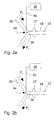
- FIG. 2 a an enlarged view of a shut-off control device of the cooling system illustrated in FIG. 1 in its first position
- FIG. 2 b an enlarged view of the shut-off control device of the cooling system illustrated in FIG. 1 in its second position.
- a cooling system 10 represented in FIG. 1 and intended for use on board an aircraft comprises a distribution line 12 , which is in communication with the pack bay 14 of the aircraft. To connect the distribution line 12 to the pack bay 14 , nozzles 17 and openings 18 are formed in the distribution line 12 .
- the cooling system 10 further comprises a coolant supply line 20 .
- a first end of the coolant supply line 20 is connected to a diffuser portion of a ram-air channel 22 and consequently to a region of the ram-air channel 22 to which a pressure above atmospheric pressure is applied.
- the region of the ram-air channel 22 to which a pressure above atmospheric pressure is applied is situated upstream of heat exchangers 24 , 26 disposed in the ram-air channel 22 .
- the cooling system 10 comprises a heat removal line 28 .
- a first end of the heat removal line 28 is connected to a region of the ram-air channel 22 to which a pressure below atmospheric pressure is applied.
- the region of the ram-air channel 22 to which a pressure below atmospheric pressure is applied lies upstream of a fan 30 disposed in the ram-air channel 22 and downstream of the heat exchangers 24 , 26 disposed in the ram-air channel 22 .
- the fan 30 is connected to a shaft 32 of the ACM of an air-conditioning unit.
- Second ends of the coolant supply line 20 and of the heat removal line 28 each are connectable to the distribution line 12 and/or separable from the distribution line 12 by means of a shut-off control device 34 .
- the shut-off control device 34 comprises an adjustable flap 36 , which is represented by dashed lines in FIG. 1 .
- Control of the shut-off control device 34 is effected by means of an electronic control unit 38 , which is connected by a line 40 to the shut-off control device 34 .
- the electronic control device 38 receives from various sensors signals indicating the operating state of the aircraft.
- the shut-off control device 34 may consequently be controlled by the electronic control unit 38 in dependence upon the operating state of the aircraft.
- the shut-off control device 34 is adjustable between a first and a second position.
- the flap 36 blocks the coolant supply line 20 and clears the heat removal line 28 .
- the flap 36 clears the coolant supply line 20 and blocks the heat removal line 28 .
- the shut-off control device 34 in its first position the shut-off control device 34 separates the distribution line 12 from the coolant supply line 20 and connects the distribution line 12 to the heat removal line 28 .
- the shut-off control device 34 connects the distribution line 12 to the coolant supply line 20 and separates the distribution line 12 from the heat removal line 28 .
- the electronic control unit 38 moves the shut-off control device 34 into its first position, in which the flap 36 connects the distribution line 12 to the heat removal line 28 .
- the coolant supply line 20 is blocked so that the connection between the distribution line 12 and the coolant supply line 20 is interrupted.
- shut-off control device 34 is initially left in its first position during the take-off phase. In this phase, the cooling of the pack bay 14 is therefore still effected by heat removal through the distribution line 12 and the heat removal line 28 .
- the electronic control unit 38 receives from the sensors of the aircraft appropriate signals indicating the conclusion of the take-off phase that the electronic control unit 38 moves the shut-off control device 34 into its second position.
- the flap 36 blocks the heat removal line 28 and clears the coolant supply line 20 , with the result that the distribution line 12 is connected to the coolant supply line 20 and separated from the heat removal line 28 .
Landscapes
- Health & Medical Sciences (AREA)
- General Health & Medical Sciences (AREA)
- Pulmonology (AREA)
- Engineering & Computer Science (AREA)
- Aviation & Aerospace Engineering (AREA)
- Air-Conditioning For Vehicles (AREA)
- Central Air Conditioning (AREA)
- Ventilation (AREA)
Abstract
Description
Claims (7)
Priority Applications (1)
| Application Number | Priority Date | Filing Date | Title |
|---|---|---|---|
| US11/956,763 US7730728B2 (en) | 2006-12-21 | 2007-12-14 | System and method for cooling a thermally loaded device on board an aircraft |
Applications Claiming Priority (9)
| Application Number | Priority Date | Filing Date | Title |
|---|---|---|---|
| US87116806P | 2006-12-21 | 2006-12-21 | |
| DE102006060765A DE102006060765B3 (en) | 2006-12-21 | 2006-12-21 | Heat loaded device e.g. air conditioning unit, cooling system for airplane, has blockage-controlling device separating distributor line from supply line, and supply line connected with area of ram air channel subjected with excess pressure |
| DE102006060765 | 2006-12-21 | ||
| DEDE102006060765.1 | 2006-12-21 | ||
| DE102007023685 | 2007-05-22 | ||
| DEDE102007023685.0 | 2007-05-22 | ||
| DE200710023685 DE102007023685B3 (en) | 2007-05-22 | 2007-05-22 | Cooling system for thermally loaded device in an aircraft has an adjustable flap with two operational positions respectively connecting the distribution line to the heat removal line and the distribution line to the cooling-air supply line |
| US93963307P | 2007-05-23 | 2007-05-23 | |
| US11/956,763 US7730728B2 (en) | 2006-12-21 | 2007-12-14 | System and method for cooling a thermally loaded device on board an aircraft |
Related Child Applications (1)
| Application Number | Title | Priority Date | Filing Date |
|---|---|---|---|
| US12/520,240 Continuation-In-Part US8707721B2 (en) | 2006-12-21 | 2007-12-12 | Ram air based cooling and ventilation system for an aircraft |
Publications (2)
| Publication Number | Publication Date |
|---|---|
| US20080148747A1 US20080148747A1 (en) | 2008-06-26 |
| US7730728B2 true US7730728B2 (en) | 2010-06-08 |
Family
ID=39540941
Family Applications (2)
| Application Number | Title | Priority Date | Filing Date |
|---|---|---|---|
| US12/520,240 Active 2031-01-13 US8707721B2 (en) | 2006-12-21 | 2007-12-12 | Ram air based cooling and ventilation system for an aircraft |
| US11/956,763 Expired - Fee Related US7730728B2 (en) | 2006-12-21 | 2007-12-14 | System and method for cooling a thermally loaded device on board an aircraft |
Family Applications Before (1)
| Application Number | Title | Priority Date | Filing Date |
|---|---|---|---|
| US12/520,240 Active 2031-01-13 US8707721B2 (en) | 2006-12-21 | 2007-12-12 | Ram air based cooling and ventilation system for an aircraft |
Country Status (8)
| Country | Link |
|---|---|
| US (2) | US8707721B2 (en) |
| EP (1) | EP2094565B1 (en) |
| JP (1) | JP2010513119A (en) |
| AT (1) | ATE483632T1 (en) |
| BR (1) | BRPI0719485A2 (en) |
| CA (1) | CA2673488A1 (en) |
| DE (1) | DE602007009722D1 (en) |
| WO (1) | WO2008074433A1 (en) |
Families Citing this family (25)
| Publication number | Priority date | Publication date | Assignee | Title |
|---|---|---|---|---|
| DE102008002116B4 (en) * | 2008-05-30 | 2014-04-10 | Airbus Operations Gmbh | Apparatus and method for the exhaust air cooling of aircraft air conditioning systems |
| DE102008030399B4 (en) * | 2008-06-26 | 2019-03-21 | Airbus Operations Gmbh | Air duct for ambient air supply in an aircraft |
| US20100084118A1 (en) * | 2008-08-21 | 2010-04-08 | Airbus Operations | Cooling system for aircraft electric or electronic devices |
| CN102639398B (en) * | 2009-09-29 | 2016-01-20 | 空中客车作业有限公司 | For cooling and/or heat the system and method for aircraft devices |
| US8757550B2 (en) * | 2010-05-25 | 2014-06-24 | Airbus Operations Limited | Method and apparatus for cooling fuel in an aircraft fuel tank |
| US9114881B2 (en) * | 2011-11-16 | 2015-08-25 | The Boeing Company | Aircraft modular cooling system |
| US9758255B1 (en) * | 2012-06-22 | 2017-09-12 | Kps, Llc | Methods and systems for controlling flammability risk in aircraft fuel tanks |
| CN103832593A (en) * | 2012-11-23 | 2014-06-04 | 空中客车作业有限公司 | Aircraft air conditioning system and method of operating an aircraft air conditioning system |
| US9669939B2 (en) * | 2013-01-16 | 2017-06-06 | Otto Aviation Group | Aircraft supplemental thrust device and method of operating the same |
| WO2014137422A1 (en) * | 2013-03-08 | 2014-09-12 | Rolls-Royce North Americantechnologies, Inc. | Aircraft and system for supplying electrical power to an aircraft electrical load |
| CN105644789B (en) * | 2014-12-05 | 2017-10-13 | 石家庄飞机工业有限责任公司 | Aircraft preshoot is pressed into gas heat-exchange device |
| DE102015216499A1 (en) | 2015-08-28 | 2017-03-02 | Airbus Operations Gmbh | Method and system for ventilating an aircraft area |
| US10399683B2 (en) * | 2016-02-16 | 2019-09-03 | The Boeing Company | Thermal management systems and methods |
| US10486816B2 (en) | 2017-04-07 | 2019-11-26 | Hamilton Sundstrand Corporation | Fan bypass and shutoff check valve |
| PH12022551859A1 (en) | 2020-01-31 | 2024-01-03 | Wisk Aero Llc | Aircraft with tilting fan assemblies |
| CN115298092A (en) | 2020-02-10 | 2022-11-04 | 威斯克航空有限责任公司 | Aircraft with propeller |
| US20210362849A1 (en) | 2020-05-19 | 2021-11-25 | Archer Aviation, Inc. | Vertical take-off and landing aircraft |
| US20230182905A1 (en) * | 2021-12-13 | 2023-06-15 | The Boeing Company | Ram air control systems and methods |
| US11912418B1 (en) | 2022-08-04 | 2024-02-27 | Greg Longe | Aircraft cabin air conditioning system |
| US11780593B1 (en) | 2022-08-04 | 2023-10-10 | Greg Longe | Aircraft cabin air conditioning system |
| US12528589B2 (en) * | 2022-08-04 | 2026-01-20 | Hamilton Sundstrand Corporation | RAM air cooling power recovery |
| US11613350B1 (en) | 2022-10-07 | 2023-03-28 | Archer Aviation, Inc. | Systems and methods for lifter motor cooling in eVTOL aircraft |
| EP4592194A3 (en) | 2022-10-07 | 2025-10-15 | Archer Aviation Inc. | Systems and methods for motor cooling in vtol aircraft |
| US12583580B2 (en) | 2022-12-12 | 2026-03-24 | Archer Aviation Inc. | Aircraft tilt apparatus including variable cooling air inlet |
| US11679872B1 (en) | 2022-12-12 | 2023-06-20 | Archer Aviation Inc. | Tilter motor cooling apparatus for vertical takeoff and landing aircraft and operating method of the same |
Citations (11)
| Publication number | Priority date | Publication date | Assignee | Title |
|---|---|---|---|---|
| US3752422A (en) * | 1971-06-30 | 1973-08-14 | Boeing Co | Jet augmented ram air scoop |
| USRE32100E (en) * | 1978-03-06 | 1986-04-01 | United Technologies Corporation | Efficiency air cycle environmental control system |
| GB2166542A (en) | 1984-11-02 | 1986-05-08 | British Aerospace | Air conditioning systems for aircraft cabins |
| US5491979A (en) * | 1993-11-26 | 1996-02-20 | Daimler-Benz Aerospace Airbus Gmbh | Apparatus for cooling food stuffs, especially in an aircraft |
| US6127758A (en) * | 1997-09-17 | 2000-10-03 | Alliedsignal Inc. | Ram air turbine system |
| US6460353B2 (en) * | 2001-03-02 | 2002-10-08 | Honeywell International Inc. | Method and apparatus for improved aircraft environmental control system utilizing parallel heat exchanger arrays |
| US20050126517A1 (en) * | 2003-12-12 | 2005-06-16 | Visteon Global Technologies, Inc. | Integrated heat exchange and fluid control device |
| US7069731B2 (en) * | 2000-11-30 | 2006-07-04 | Honeywell Normalair-Garrett (Holdings) Limited | Cooling apparatus |
| EP1695910A2 (en) | 2005-02-24 | 2006-08-30 | Hamilton Sundstrand Corporation | On-board inert gas generation system with compressor surge protection |
| US7305842B1 (en) * | 2005-05-23 | 2007-12-11 | Peter Schiff | Environmental control system and method for an aircraft |
| US7334423B2 (en) * | 2004-09-22 | 2008-02-26 | Hamilton Sundstrand Corporation | Dual mode condensing cycle |
Family Cites Families (17)
| Publication number | Priority date | Publication date | Assignee | Title |
|---|---|---|---|---|
| US2704925A (en) * | 1952-10-20 | 1955-03-29 | Garrett Corp | Air conditioner having air expansion means |
| US2767561A (en) * | 1954-05-20 | 1956-10-23 | Boeing Co | Ram air cabin pressurizing systems |
| US2966308A (en) * | 1955-01-31 | 1960-12-27 | Garrett Corp | Cabin temperature system |
| US3076604A (en) * | 1959-10-30 | 1963-02-05 | American Air Filter Co | Control system for air heater |
| US4021215A (en) * | 1976-05-03 | 1977-05-03 | United Technologies Corporation | Dual combined cycle air-conditioning system |
| US4674704A (en) * | 1985-12-03 | 1987-06-23 | The United States Of America As Represented By The Secretary Of The Air Force | Direct air cooling system for airborne electronics |
| US5669813A (en) * | 1996-05-03 | 1997-09-23 | Ford Motor Company | Apparatus for storing and cooling electronic devices and/or modules in a vehicle |
| US5887445A (en) * | 1997-11-11 | 1999-03-30 | Alliedsignal Inc. | Two spool environmental control system |
| DE10015570B4 (en) * | 2000-03-29 | 2007-11-22 | Airbus Deutschland Gmbh | Arrangement for forced guidance of a cooling air flow within a refrigeration unit for a commercial aircraft |
| DE10119433C1 (en) | 2001-04-20 | 2002-08-22 | Liebherr Aerospace Gmbh | Ram air duct for an aircraft air conditioning system |
| US7349906B2 (en) * | 2003-07-15 | 2008-03-25 | Hewlett-Packard Development Company, L.P. | System and method having improved efficiency for distributing a file among a plurality of recipients |
| DE10350541A1 (en) * | 2003-10-29 | 2005-06-16 | Liebherr-Aerospace Lindenberg Gmbh | Air conditioning system and method for treating air for air conditioning of a room |
| US7081153B2 (en) | 2003-12-02 | 2006-07-25 | Honeywell International Inc. | Gas generating system and method for inerting aircraft fuel tanks |
| DE10361657B4 (en) | 2003-12-30 | 2008-06-26 | Airbus Deutschland Gmbh | Cooling air supply system for the cooling of various cooling air requiring systems in an aircraft |
| DE102004039667A1 (en) * | 2004-08-16 | 2006-03-02 | Airbus Deutschland Gmbh | Air supply device for gas generating system in aircraft, supplies bleeding air from air generation system heat exchanger to on-board inert gas generation system |
| RU2392196C2 (en) | 2004-08-16 | 2010-06-20 | Эйрбас Дойчланд Гмбх | Device and method of air feed for inert gas generation and their application at aircraft |
| RU45711U1 (en) | 2004-11-10 | 2005-05-27 | Открытое акционерное общество Научно-производственное объединение "Наука" (ОАО НПО "Наука") | AIRCRAFT AIR CONDITIONING SYSTEM |
-
2007
- 2007-12-12 BR BRPI0719485-4A2A patent/BRPI0719485A2/en not_active IP Right Cessation
- 2007-12-12 CA CA002673488A patent/CA2673488A1/en not_active Abandoned
- 2007-12-12 AT AT07856666T patent/ATE483632T1/en not_active IP Right Cessation
- 2007-12-12 US US12/520,240 patent/US8707721B2/en active Active
- 2007-12-12 EP EP07856666A patent/EP2094565B1/en not_active Not-in-force
- 2007-12-12 JP JP2009541849A patent/JP2010513119A/en active Pending
- 2007-12-12 WO PCT/EP2007/010920 patent/WO2008074433A1/en not_active Ceased
- 2007-12-12 DE DE602007009722T patent/DE602007009722D1/en active Active
- 2007-12-14 US US11/956,763 patent/US7730728B2/en not_active Expired - Fee Related
Patent Citations (11)
| Publication number | Priority date | Publication date | Assignee | Title |
|---|---|---|---|---|
| US3752422A (en) * | 1971-06-30 | 1973-08-14 | Boeing Co | Jet augmented ram air scoop |
| USRE32100E (en) * | 1978-03-06 | 1986-04-01 | United Technologies Corporation | Efficiency air cycle environmental control system |
| GB2166542A (en) | 1984-11-02 | 1986-05-08 | British Aerospace | Air conditioning systems for aircraft cabins |
| US5491979A (en) * | 1993-11-26 | 1996-02-20 | Daimler-Benz Aerospace Airbus Gmbh | Apparatus for cooling food stuffs, especially in an aircraft |
| US6127758A (en) * | 1997-09-17 | 2000-10-03 | Alliedsignal Inc. | Ram air turbine system |
| US7069731B2 (en) * | 2000-11-30 | 2006-07-04 | Honeywell Normalair-Garrett (Holdings) Limited | Cooling apparatus |
| US6460353B2 (en) * | 2001-03-02 | 2002-10-08 | Honeywell International Inc. | Method and apparatus for improved aircraft environmental control system utilizing parallel heat exchanger arrays |
| US20050126517A1 (en) * | 2003-12-12 | 2005-06-16 | Visteon Global Technologies, Inc. | Integrated heat exchange and fluid control device |
| US7334423B2 (en) * | 2004-09-22 | 2008-02-26 | Hamilton Sundstrand Corporation | Dual mode condensing cycle |
| EP1695910A2 (en) | 2005-02-24 | 2006-08-30 | Hamilton Sundstrand Corporation | On-board inert gas generation system with compressor surge protection |
| US7305842B1 (en) * | 2005-05-23 | 2007-12-11 | Peter Schiff | Environmental control system and method for an aircraft |
Also Published As
| Publication number | Publication date |
|---|---|
| JP2010513119A (en) | 2010-04-30 |
| WO2008074433A1 (en) | 2008-06-26 |
| EP2094565B1 (en) | 2010-10-06 |
| US8707721B2 (en) | 2014-04-29 |
| EP2094565A1 (en) | 2009-09-02 |
| BRPI0719485A2 (en) | 2014-02-18 |
| CA2673488A1 (en) | 2008-06-26 |
| US20080148747A1 (en) | 2008-06-26 |
| US20100096118A1 (en) | 2010-04-22 |
| ATE483632T1 (en) | 2010-10-15 |
| DE602007009722D1 (en) | 2010-11-18 |
Similar Documents
| Publication | Publication Date | Title |
|---|---|---|
| US7730728B2 (en) | System and method for cooling a thermally loaded device on board an aircraft | |
| CN101155728B (en) | System and method for cargo compartment air conditioning using recirculated air | |
| EP2947012B1 (en) | Aircraft air conditioning system and method of its operation | |
| EP2998223B1 (en) | Aircraft air conditioning system and method of operating an aircraft air conditioning system | |
| CN102007037B (en) | De-icing system for an airplane | |
| EP2076437B1 (en) | Air supply system of an aircraft and method for mixing two air streams in an air supply system | |
| US9011218B2 (en) | System and method for ventilating explosive regions of an aircraft | |
| US7040112B2 (en) | Air conditioning system | |
| EP3144224B1 (en) | Ram air channel arrangement and method for operating a ram air channel arrangement | |
| US9623973B2 (en) | Cooling concept for fuel cell emergency power supply | |
| US10155592B2 (en) | Environmental control system with air cycle machine bypass shutoff valves | |
| CN101883720B (en) | Air conditioning system with mixed mode bleed operation | |
| US6442944B1 (en) | Bleed air heat exchanger integral to a jet engine | |
| EP2868579B1 (en) | Aircraft air conditioning system and method of operating an aircraft air conditioning system | |
| JP4787832B2 (en) | Air supply to aircraft | |
| EP2805883B1 (en) | Aircraft cooling system | |
| US9657648B2 (en) | Environmental air conditioning system | |
| JP5559806B2 (en) | Emergency ventilation method and system for aircraft cabin in case of leak around air mixer | |
| US20200247548A1 (en) | Apparatus and methods for providing air to pneumatic loads onboard aircraft | |
| CN110040254A (en) | Vehicles air-conditioning sub-assembly with air circulation component | |
| US8708786B2 (en) | Aircraft air-conditioning system with a reduced risk of icing | |
| US6886782B2 (en) | System for supplying an aircraft with cool air | |
| US7922118B2 (en) | System for producing process air | |
| JP2004090778A (en) | Air conditioner for aircraft | |
| US6786279B2 (en) | Forward in flight (IFE) entertainment cooling system |
Legal Events
| Date | Code | Title | Description |
|---|---|---|---|
| AS | Assignment |
Owner name: AIRBUS DEUTSCHLAND GMBH, GERMANY Free format text: ASSIGNMENT OF ASSIGNORS INTEREST;ASSIGNORS:SOLNTSEV, ALEXANDER;BAMMANN, HOLGER;REEL/FRAME:020629/0560 Effective date: 20080111 Owner name: AIRBUS DEUTSCHLAND GMBH,GERMANY Free format text: ASSIGNMENT OF ASSIGNORS INTEREST;ASSIGNORS:SOLNTSEV, ALEXANDER;BAMMANN, HOLGER;REEL/FRAME:020629/0560 Effective date: 20080111 |
|
| FEPP | Fee payment procedure |
Free format text: PAYOR NUMBER ASSIGNED (ORIGINAL EVENT CODE: ASPN); ENTITY STATUS OF PATENT OWNER: LARGE ENTITY |
|
| AS | Assignment |
Owner name: AIRBUS OPERATIONS GMBH, GERMANY Free format text: CHANGE OF NAME;ASSIGNOR:AIRBUS DEUTSCHLAND GMBH;REEL/FRAME:026360/0849 Effective date: 20090602 |
|
| FPAY | Fee payment |
Year of fee payment: 4 |
|
| FEPP | Fee payment procedure |
Free format text: MAINTENANCE FEE REMINDER MAILED (ORIGINAL EVENT CODE: REM.) |
|
| LAPS | Lapse for failure to pay maintenance fees |
Free format text: PATENT EXPIRED FOR FAILURE TO PAY MAINTENANCE FEES (ORIGINAL EVENT CODE: EXP.) |
|
| STCH | Information on status: patent discontinuation |
Free format text: PATENT EXPIRED DUE TO NONPAYMENT OF MAINTENANCE FEES UNDER 37 CFR 1.362 |
|
| FP | Lapsed due to failure to pay maintenance fee |
Effective date: 20180608 |