US7703594B2 - Escalator or moving sidewalk - Google Patents
Escalator or moving sidewalk Download PDFInfo
- Publication number
- US7703594B2 US7703594B2 US10/593,168 US59316805A US7703594B2 US 7703594 B2 US7703594 B2 US 7703594B2 US 59316805 A US59316805 A US 59316805A US 7703594 B2 US7703594 B2 US 7703594B2
- Authority
- US
- United States
- Prior art keywords
- escalator
- frame
- moving sidewalk
- holes
- side plates
- Prior art date
- Legal status (The legal status is an assumption and is not a legal conclusion. Google has not performed a legal analysis and makes no representation as to the accuracy of the status listed.)
- Expired - Lifetime, expires
Links
Images


Classifications
-
- B—PERFORMING OPERATIONS; TRANSPORTING
- B66—HOISTING; LIFTING; HAULING
- B66B—ELEVATORS; ESCALATORS OR MOVING WALKWAYS
- B66B23/00—Component parts of escalators or moving walkways
Definitions
- the invention relates to an escalator or moving sidewalk.
- Corresponding chain rollers and step rollers typically each run on separate rails supported by a frame made of sections.
- the rails In order to form the required step pattern or to provide the desired pallet band, the rails have to run at a given height and be supported safely and in particular also rigidly there. If the rail were to bend too much, not only would the passenger be given a feeling of insecurity, there would also be a risk that in the event of an asymmetric load of the step or pallet band, the specified clearance would be exceeded so that the step or pallet would scrape on the rail.
- the frames used are particularly rigid and do not bend beyond the given tolerances even in the event of the maximum permissible operating load of the escalator, but also for example of a self-supporting moving sidewalk.
- a further problem is the high cost for creation of the supporting structure.
- the frames are typically prefabricated in sections of, for example, 2 m or 3 m in length by welding together the sections at the factory. On site they are then lifted to the desired position with cranes or lifting platforms or similar equipment and welded together there.
- This solution is extremely time and labor-intensive, requires heavy equipment and is a major contribution to the costs for the construction of the escalator.
- the object of the invention is therefore to create an escalator or moving sidewalk that is lighter in weight without losing rigidity so that it can also be used for buildings with a low load-bearing strength while at the same time reducing the manufacturing costs.
- an escalator or moving sidewalk comprising a frame to form a supporting structure between an entry and an exit, wherein the frame is composed at least partially of a perforated plate structure having round holes or hole cut-outs in particular on the side surfaces of the frame, and wherein the holes or hole cut-outs are provided over a significant portion of the height of the frame, preferably over approximately over half of the height of the frame.
- perforated plate that form the frame as a perforated plate frame.
- perforated plate it goes without saying that this does not mean a prior art perforated plate, but a specially manufactured plate in which large holes are made arranged alternately and in various sizes, whereby the largest holes can, for example, quite easily have half the height of a side plate, in other words can have a diameter of, for example, 50 cm.
- a perforated plate with large holes according to the invention can be manufactured by any suitable means.
- the perforated plates according to the invention can be produced by cutting, for example laser cutting, but also using any other plate cutting techniques.
- the perforated plate structure according to the invention permits a significantly reduced weight to be achieved compared with the manufacture using welded U and T sections; surprisingly, with the same bending of an escalator of 20 m length, the weight of the frame is reduced to roughly one half.
- the prefabricated long sections of side plates and base plates can be manufactured far less expensively using the solution according to the invention.
- the significantly reduced wall thicknesses allow the frame to be handled better on site, and the necessary load-bearing strength of the floor ceilings is greatly reduced in view of the considerably reduced weight.
- the heavy equipment used for installation can also be reduced, with the use of cranes possibly becoming even dispensable.
- the solution according to the invention provides an exceptionally rigid supporting construction for the frame.
- the weld seams of base plate and side plates provided for on site are preferably not made at the same point in the longitudinal direction, but are offset from one another, thus additionally enhancing the rigidity.
- a laser cutter and laser welder such constructions can be produced inexpensively, automatically and quickly away from the factory, so that the manufacturing time is significantly reduced.
- an escalator manufacturer can work with lower stocks of prefabricated sections and corresponding elements, further reducing production costs.
- the removal of material of the holes cut out of the plates to produce the large-hole perforated plate according to the invention does not essentially result in a weakening of the plate used, and on the other hand a significant reduction in weight of, for example, 40% can be achieved, depending on the arrangement of the cut holes. While circular holes are preferred, ft goes without saying that elliptical holes can in some circumstances also have benefits.
- the circular cut-outs from the plate represent high-quality and recyclable sheet steel so that the solution according to the invention does not result in any cost disadvantages for the waste disposal either.
- the prefabricated plate sections can have a length of one meter and a grid arrangement of 4 units.
- An alternative modified embodiment of the escalator according to the invention provides for the plates cut to length in the grid dimensions to overlap so that the adaptation area provided for once with each escalator or moving sidewalk involves certain weight disadvantages over a length of less than 1 meter, but that no loss of rigidity is to be expected at these critical points.
- the upper run and lower run of the step or pallet band typically run with a significant distance between them. At the entry and exit, the distance is determined by the diameter of the drive wheel or deflection wheel of the step or pallet chain.
- transverse struts can consist of folded plate, but can also be constructed as profiled sections.
- An advantageous embodiment provides for the return drums adjacent to the entry and exit to also be manufactured from large-hole perforated plate.
- a corresponding plate can be prefabricated with a width of, for example 1.50 m as a basis rather like the base plate, while the side plates extending over the length of the escalator or moving sidewalk can be made from plates with a width of approx 1 m.
- flat plates should be cut by laser. If necessary, the plates can also be edged at the ends, for example by rolling. It goes without saying that in order to achieve the desired strength, the dimensioning of the plates is adapted to the requirements.
- the desired large-hole plate structure is obtained with flat plates by laser cutting and the connection to plates running transversely to these is made by laser welding. It goes without saying, however, that, particularly when working on site, any other welding techniques can also be employed.
- the side plates are placed on the base plate and welded there, preferably with a continuous weld seam, during prefabrication at the factory. It goes without saying that any other suitable method of joining can also be employed, possibly also riveting after corresponding edging of one of the plates.
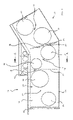
- FIG. 1 shows a side view of one part of an embodiment of an escalator according to the invention, namely a side plate;
- FIG. 2 shows a side view of one part of the embodiment according to FIG. 1 , namely another side plate;
- FIG. 3 shows a section through the escalator according to the invention in the embodiment according to FIG. 1 , along the line A-A;
- FIG. 4 shows a section through the escalator according to the invention in the embodiment according to FIG. 1 , along the line B-B;
- FIG. 5 shows a section through the escalator according to the invention in the embodiment according to FIG. 2 , along the line C-C.
- the escalator 10 shown partly in FIG. 1 in the embodiment according to the invention exhibits a perforated plate frame 12 that has an essentially U shape.
- FIG. 1 shows a side view of the U, in other words a view of one of the side legs.
- the side legs are formed by side plates, one side plate 14 of which can be seen in FIG. 1 , while the middle leg is formed in each case by a base plate as can be seen in the form of the base plate 18 in FIG. 3 .
- the side plate 14 shown in FIG. 1 exists here in the form of a side plate cut-out that is intended for the form entry or exit of the escalator.
- the part of the side plate 14 pointing upwards at an angle is essentially connected to further side plates so that the combination of the end side plates shown in FIGS. 1 and 2 and the middle side plates extending between these form the complete side plates of the escalator.
- the side plate 14 exhibits a large-hole plate structure 20 .
- a hole cut-out 22 extends over a height of just about 60% of the side plate 14 and closer to the upper edge of the side plate 14 .
- hole cut-out 22 At a distance from the hole cut-out 22 and offset from it extends a slightly smaller hole cut-out 24 closer to the lower end of the side plate 14 .
- hole transitions 26 Between the hole cut-outs 22 and 24 are hole transitions 26 whose width, size, position and inclination can be extensively adapted to the requirements. The orientation of adjacent hole transitions differently from one another is preferred.
- the hole cut-outs 22 and 24 are not, however, arranged alternately at the top and bottom of the side plate.
- the hole cut-out 22 is in fact adjacent to a quite small hole cut-out 28 that is also arranged at the upper end, while a quite narrow hole transition 30 extends between the hole cutout 22 and the hole cut-out 28 .
- further hole cut-outs 31 , 32 and 33 extend in different distributions, while hole transitions 34 , 35 and 36 are located between adjacent hole cut-outs.
- Adjacent hole cut-outs or holes are at least either not at the same height or do not have the same diameter. Thanks to this arrangement by way of a stochastically distributed arrangement it is possible to obtain a low-resonance structure of the large-hole plate 20 according to the invention.
- the perforated plates are produced by cutting corresponding round holes 32 out of the initially complete plate. Cutting out can be performed in any suitable manner, but preferably by laser cutting.
- the holes are preferably round so that the introduced force is homogenized without stress concentrations.
- the perforated plate structure 20 shown in FIG. 1 is given additional rigidity by further ribs.
- Examples here are the ribs 37 and 39 .
- the ribs 37 run through the hole transition 30 perpendicularly to the main orientation of the side plate 14 almost to the base plate 18 .
- the ribs 39 run through the hole transition 35 and extend essentially also over the whole height of the side plate 14 .
- the ribs each extend inward, for example over a width of 5 cm. They are formed by plate strips welded on there.
- transverse struts 40 are provided roughly in the middle of the hole transitions 35 and extend between the two side legs of the U. Such transverse struts can be seen, for example, in FIGS. 4 and 5 .
- a protruding section 42 is provided at the top of the side plates 14 in a manner as illustrated in FIG. 1 and FIG. 3 .
- the head plate of the escalator according to the invention can be supported at this point.
- the frame according to the invention is terminated by an L section 46 that extends between the two side walls 14 .
- FIG. 2 shows a corresponding construction of a side plate portion for the upper entry or exit.
- a protruding section 48 is also provided that extends beyond the upper rib 22 and whose design can be seen from FIG. 5 .
- the side plates 14 according to the invention are linked by a base plate 18 .
- the base plate 18 also preferably exhibits hole cut-outs 50 not illustrated here. It is preferred that in the area of the ribs 38 , and hence quite far to the side, no cut-outs are provided in order to guarantee full-surface support for the welded-on ribs 38 .
- the frame according to the invention of the escalator in accordance with the invention is exceptionally rigid both as a section and when welded together and exhibits a particular low weight in relationship hereto. It goes without saying that the width and arrangement of the hole cut-outs can be extensively adapted to the requirements. Furthermore, production is not limited to laser cutting and laser welding; any other form of material separation and material joining can be employed. The plate thickness can also be extensively varied, depending on the demand profile, in order to provide the desired strength.
Landscapes
- Escalators And Moving Walkways (AREA)
Abstract
Description
Claims (19)
Applications Claiming Priority (4)
| Application Number | Priority Date | Filing Date | Title |
|---|---|---|---|
| DE202004004178U DE202004004178U1 (en) | 2004-03-17 | 2004-03-17 | Escalator or moving walk |
| DE202004004178.2 | 2004-03-17 | ||
| DE202004004178U | 2004-03-17 | ||
| PCT/EP2005/002853 WO2005090220A2 (en) | 2004-03-17 | 2005-03-17 | Escalator or moving sidewalk |
Publications (2)
| Publication Number | Publication Date |
|---|---|
| US20080257682A1 US20080257682A1 (en) | 2008-10-23 |
| US7703594B2 true US7703594B2 (en) | 2010-04-27 |
Family
ID=33039459
Family Applications (1)
| Application Number | Title | Priority Date | Filing Date |
|---|---|---|---|
| US10/593,168 Expired - Lifetime US7703594B2 (en) | 2004-03-17 | 2005-03-17 | Escalator or moving sidewalk |
Country Status (5)
| Country | Link |
|---|---|
| US (1) | US7703594B2 (en) |
| EP (1) | EP1737778A2 (en) |
| CN (1) | CN1953930A (en) |
| DE (1) | DE202004004178U1 (en) |
| WO (1) | WO2005090220A2 (en) |
Cited By (7)
| Publication number | Priority date | Publication date | Assignee | Title |
|---|---|---|---|---|
| US20090101470A1 (en) * | 2007-10-18 | 2009-04-23 | Thyssenkrupp Elevator Innovation Center, S.A. | Self-supporting guiding system for moving walkways |
| EP2433893A1 (en) * | 2010-09-24 | 2012-03-28 | Inventio AG | Passenger transport device |
| US20130192952A1 (en) * | 2009-12-23 | 2013-08-01 | Otis Elevator Company | Profile track integrated drive system |
| US20140360836A1 (en) * | 2013-06-07 | 2014-12-11 | Kone Corporation | Truss device and an escalator or moving walk |
| RU2588556C2 (en) * | 2011-08-30 | 2016-06-27 | Инвецнио Аг | Moving stairway or moving walkways with bottom sheet |
| US10562133B2 (en) * | 2016-03-10 | 2020-02-18 | Inventio Ag | Method for a robot-assisted assembly of a supporting structure for a passenger transport system |
| US11407051B2 (en) * | 2016-03-10 | 2022-08-09 | Inventio Ag | Device for the robot-assisted manufacturing of a supporting structure for a passenger transport system |
Families Citing this family (10)
| Publication number | Priority date | Publication date | Assignee | Title |
|---|---|---|---|---|
| JP5371367B2 (en) * | 2008-10-22 | 2013-12-18 | 株式会社日立製作所 | Manufacturing method of escalator frame |
| JP5231944B2 (en) * | 2008-10-30 | 2013-07-10 | 株式会社日立製作所 | Passenger conveyor |
| JP5143760B2 (en) * | 2009-01-29 | 2013-02-13 | 株式会社日立製作所 | Passenger conveyor |
| JP5011324B2 (en) * | 2009-02-18 | 2012-08-29 | 株式会社日立製作所 | Passenger conveyor |
| CN102363483A (en) * | 2011-06-29 | 2012-02-29 | 苏州新达电扶梯部件有限公司 | Elevator guardrail inclined baffle |
| CN104462267A (en) * | 2014-11-23 | 2015-03-25 | 国云科技股份有限公司 | A Method of Realizing Fast Data Query |
| DE102014224457A1 (en) * | 2014-11-28 | 2016-06-02 | Thyssenkrupp Ag | Carrying structure for a conveyor |
| DE102014224460A1 (en) * | 2014-11-28 | 2016-06-02 | Thyssenkrupp Ag | Carrying structure for a conveyor |
| EP4353652A1 (en) * | 2022-10-10 | 2024-04-17 | TK Elevator Innovation and Operations GmbH | Method for assembling at least one longitudinal section module of a modularly assemblable trackway device, and trackway device |
| EP4353663A1 (en) * | 2022-10-10 | 2024-04-17 | TK Elevator Innovation and Operations GmbH | Method for producing a component of a track device |
Citations (12)
| Publication number | Priority date | Publication date | Assignee | Title |
|---|---|---|---|---|
| US2936872A (en) * | 1957-05-24 | 1960-05-17 | Rheinstahl Hamburg Stahlbau Eg | Moving stairways |
| DE2010662A1 (en) | 1970-03-06 | 1971-09-16 | Maschf Augsburg Nuernberg Ag | Construction for means of transport such as moving walks, escalators or the like |
| DE2519310A1 (en) | 1974-04-30 | 1975-11-13 | Mechaniplan Proprietary Ltd | CONVEYOR DEVICE |
| DE8134167U1 (en) | 1981-11-24 | 1982-04-15 | Stahlbau Löw GmbH & Co KG, 7129 Güglingen | "STRUCTURE COMPOSED FROM INDIVIDUAL COMPONENTS FOR A HORIZONTAL CONVEYOR" |
| US4811829A (en) | 1986-05-10 | 1989-03-14 | Hitachi Ltd . | Frame of passenger conveyor |
| DE4117901A1 (en) | 1991-04-16 | 1992-10-22 | Orenstein & Koppel Ag | SUPPORT CONSTRUCTION FOR GUIDING TAPE CONVEYORS, ESPECIALLY TUBE CONVEYORS |
| US6374981B1 (en) * | 1999-08-06 | 2002-04-23 | Invento Ag | Support construction for long escalators and moving walkways |
| US20020175039A1 (en) | 2001-05-11 | 2002-11-28 | Fargo Richard N. | Escalator support structure |
| EP1273548A1 (en) | 2001-07-02 | 2003-01-08 | Inventio Ag | Escalator or moving walkway with support structure |
| DE10146205A1 (en) | 2001-09-19 | 2003-04-10 | Kone Corp | Base for escalator or moving walkway has termination region provided by termination element having spaced plate elements and intermediate reinforcing elements |
| US20030116402A1 (en) | 2001-12-19 | 2003-06-26 | David Krampl | Support construction |
| JP2004018152A (en) | 2002-06-14 | 2004-01-22 | Hitachi Ltd | escalator |
-
2004
- 2004-03-17 DE DE202004004178U patent/DE202004004178U1/en not_active Expired - Lifetime
-
2005
- 2005-03-17 CN CNA2005800083893A patent/CN1953930A/en active Pending
- 2005-03-17 EP EP05716158A patent/EP1737778A2/en not_active Withdrawn
- 2005-03-17 WO PCT/EP2005/002853 patent/WO2005090220A2/en not_active Ceased
- 2005-03-17 US US10/593,168 patent/US7703594B2/en not_active Expired - Lifetime
Patent Citations (13)
| Publication number | Priority date | Publication date | Assignee | Title |
|---|---|---|---|---|
| US2936872A (en) * | 1957-05-24 | 1960-05-17 | Rheinstahl Hamburg Stahlbau Eg | Moving stairways |
| DE2010662A1 (en) | 1970-03-06 | 1971-09-16 | Maschf Augsburg Nuernberg Ag | Construction for means of transport such as moving walks, escalators or the like |
| DE2519310A1 (en) | 1974-04-30 | 1975-11-13 | Mechaniplan Proprietary Ltd | CONVEYOR DEVICE |
| DE8134167U1 (en) | 1981-11-24 | 1982-04-15 | Stahlbau Löw GmbH & Co KG, 7129 Güglingen | "STRUCTURE COMPOSED FROM INDIVIDUAL COMPONENTS FOR A HORIZONTAL CONVEYOR" |
| US4811829A (en) | 1986-05-10 | 1989-03-14 | Hitachi Ltd . | Frame of passenger conveyor |
| DE4117901A1 (en) | 1991-04-16 | 1992-10-22 | Orenstein & Koppel Ag | SUPPORT CONSTRUCTION FOR GUIDING TAPE CONVEYORS, ESPECIALLY TUBE CONVEYORS |
| US6374981B1 (en) * | 1999-08-06 | 2002-04-23 | Invento Ag | Support construction for long escalators and moving walkways |
| US20020175039A1 (en) | 2001-05-11 | 2002-11-28 | Fargo Richard N. | Escalator support structure |
| EP1273548A1 (en) | 2001-07-02 | 2003-01-08 | Inventio Ag | Escalator or moving walkway with support structure |
| DE10146205A1 (en) | 2001-09-19 | 2003-04-10 | Kone Corp | Base for escalator or moving walkway has termination region provided by termination element having spaced plate elements and intermediate reinforcing elements |
| US20030116402A1 (en) | 2001-12-19 | 2003-06-26 | David Krampl | Support construction |
| US6814215B2 (en) * | 2001-12-19 | 2004-11-09 | Inventio Ag | Support construction |
| JP2004018152A (en) | 2002-06-14 | 2004-01-22 | Hitachi Ltd | escalator |
Cited By (13)
| Publication number | Priority date | Publication date | Assignee | Title |
|---|---|---|---|---|
| US8042675B2 (en) * | 2007-10-18 | 2011-10-25 | Thyssenkrupp Elevator Innovation Center, S.A. | Self-supporting guiding system for moving walkways |
| US20090101470A1 (en) * | 2007-10-18 | 2009-04-23 | Thyssenkrupp Elevator Innovation Center, S.A. | Self-supporting guiding system for moving walkways |
| US20130192952A1 (en) * | 2009-12-23 | 2013-08-01 | Otis Elevator Company | Profile track integrated drive system |
| CN103118967B (en) * | 2010-09-24 | 2016-05-04 | 因温特奥股份公司 | person conveying device |
| CN103118967A (en) * | 2010-09-24 | 2013-05-22 | 因温特奥股份公司 | People conveyor |
| WO2012038328A1 (en) * | 2010-09-24 | 2012-03-29 | Inventio Ag | People conveyor |
| US8919527B2 (en) | 2010-09-24 | 2014-12-30 | Inventio Ag | Conveying equipment for persons |
| EP2433893A1 (en) * | 2010-09-24 | 2012-03-28 | Inventio AG | Passenger transport device |
| RU2588556C2 (en) * | 2011-08-30 | 2016-06-27 | Инвецнио Аг | Moving stairway or moving walkways with bottom sheet |
| US20140360836A1 (en) * | 2013-06-07 | 2014-12-11 | Kone Corporation | Truss device and an escalator or moving walk |
| US9038806B2 (en) * | 2013-06-07 | 2015-05-26 | Kone Corporation | Truss device and an escalator or moving walk |
| US10562133B2 (en) * | 2016-03-10 | 2020-02-18 | Inventio Ag | Method for a robot-assisted assembly of a supporting structure for a passenger transport system |
| US11407051B2 (en) * | 2016-03-10 | 2022-08-09 | Inventio Ag | Device for the robot-assisted manufacturing of a supporting structure for a passenger transport system |
Also Published As
| Publication number | Publication date |
|---|---|
| WO2005090220A3 (en) | 2006-04-20 |
| CN1953930A (en) | 2007-04-25 |
| WO2005090220A2 (en) | 2005-09-29 |
| US20080257682A1 (en) | 2008-10-23 |
| EP1737778A2 (en) | 2007-01-03 |
| DE202004004178U1 (en) | 2004-09-23 |
Similar Documents
| Publication | Publication Date | Title |
|---|---|---|
| US7703594B2 (en) | Escalator or moving sidewalk | |
| KR101144586B1 (en) | Steel built-up beam having closed section for applying long span and reduction of height and concrete filled composite beam system using the same | |
| CA2774271C (en) | Improved cold-formed steel joist | |
| CA2315286C (en) | Support construction for long escalators and moving walkways | |
| US6814215B2 (en) | Support construction | |
| US20070000197A1 (en) | Structural decking system | |
| US5586418A (en) | Composite construction of reinforced concrete | |
| KR101747097B1 (en) | Steeel reinforcement truss deck plate with transverse steel structure and manufacturing method thereof | |
| EP2689075B1 (en) | System for reinforcing concrete slabs | |
| WO2007085076A1 (en) | A composite floor apparatus and a method of making and using same with building supports | |
| KR101105404B1 (en) | End continuous deck plate system with cap plate | |
| JP5047060B2 (en) | Synthetic floor slab and its reinforcement method | |
| WO2007141370A1 (en) | Steel plate beam and manufacturing method of such | |
| KR101329372B1 (en) | Deflection control structure of deck plate of slim floor with demountable tendon and construction method thereof | |
| KR101464349B1 (en) | Steel beam having exposed upper flange for parking building | |
| KR101329482B1 (en) | Deflection control structure of deck plate of slim floor with stiffness reinforcing link bar and construction method thereof | |
| KR20100018170A (en) | Inverted triangle truss slab form | |
| KR102720602B1 (en) | Composite structure of steel semi-section deck for rapid construction of bridges and its manufacturing method | |
| KR200317407Y1 (en) | Truss Deck Panel | |
| JP2017193946A (en) | Heavy machinery support mechanism | |
| KR102720603B1 (en) | Rapid construction method of bridge using segmented steel half-sided deck composite structure | |
| KR20110087838A (en) | Steel Plate Assembled Beam for Structural Reduction | |
| JP3204846U (en) | Double folded plate roof structure | |
| AU2004206038B2 (en) | Structural decking system | |
| KR102586172B1 (en) | H-beam having tube upper-flange |
Legal Events
| Date | Code | Title | Description |
|---|---|---|---|
| AS | Assignment |
Owner name: THYSSEN FAHRTREPPEN, GERMANY Free format text: ASSIGNMENT OF ASSIGNORS INTEREST;ASSIGNOR:STEIN, WOLFGANG;REEL/FRAME:018325/0414 Effective date: 20051124 |
|
| AS | Assignment |
Owner name: THYSSENKRUPP FAHRTREPPEN GMBH, GERMANY Free format text: CORRECTIVE TO CORRECT THE NAME OF THE ASSIGNEE. PREVIOUSLY RECORDED ON REEL 018325 FRAME 0414.;ASSIGNOR:STEIN, WOLFGANG;REEL/FRAME:018509/0874 Effective date: 20051124 |
|
| STCF | Information on status: patent grant |
Free format text: PATENTED CASE |
|
| FPAY | Fee payment |
Year of fee payment: 4 |
|
| FEPP | Fee payment procedure |
Free format text: PAYOR NUMBER ASSIGNED (ORIGINAL EVENT CODE: ASPN); ENTITY STATUS OF PATENT OWNER: LARGE ENTITY |
|
| MAFP | Maintenance fee payment |
Free format text: PAYMENT OF MAINTENANCE FEE, 8TH YEAR, LARGE ENTITY (ORIGINAL EVENT CODE: M1552) Year of fee payment: 8 |
|
| MAFP | Maintenance fee payment |
Free format text: PAYMENT OF MAINTENANCE FEE, 12TH YEAR, LARGE ENTITY (ORIGINAL EVENT CODE: M1553); ENTITY STATUS OF PATENT OWNER: LARGE ENTITY Year of fee payment: 12 |