US7703391B2 - Round baler with scale and moisture meter - Google Patents
Round baler with scale and moisture meter Download PDFInfo
- Publication number
- US7703391B2 US7703391B2 US11/460,812 US46081206A US7703391B2 US 7703391 B2 US7703391 B2 US 7703391B2 US 46081206 A US46081206 A US 46081206A US 7703391 B2 US7703391 B2 US 7703391B2
- Authority
- US
- United States
- Prior art keywords
- belt tensioner
- bale
- tension
- relief valve
- hydraulic damper
- Prior art date
- Legal status (The legal status is an assumption and is not a legal conclusion. Google has not performed a legal analysis and makes no representation as to the accuracy of the status listed.)
- Active, expires
Links
Images


Classifications
-
- A—HUMAN NECESSITIES
- A01—AGRICULTURE; FORESTRY; ANIMAL HUSBANDRY; HUNTING; TRAPPING; FISHING
- A01F—PROCESSING OF HARVESTED PRODUCE; HAY OR STRAW PRESSES; DEVICES FOR STORING AGRICULTURAL OR HORTICULTURAL PRODUCE
- A01F15/00—Baling presses for straw, hay or the like
- A01F15/07—Rotobalers, i.e. machines for forming cylindrical bales by winding and pressing
- A01F15/071—Wrapping devices
- A01F15/0715—Wrapping the bale in the press chamber before opening said chamber
-
- A—HUMAN NECESSITIES
- A01—AGRICULTURE; FORESTRY; ANIMAL HUSBANDRY; HUNTING; TRAPPING; FISHING
- A01F—PROCESSING OF HARVESTED PRODUCE; HAY OR STRAW PRESSES; DEVICES FOR STORING AGRICULTURAL OR HORTICULTURAL PRODUCE
- A01F15/00—Baling presses for straw, hay or the like
- A01F15/08—Details
- A01F15/0825—Regulating or controlling density or shape of the bale
- A01F15/0833—Regulating or controlling density or shape of the bale for round balers
-
- A—HUMAN NECESSITIES
- A01—AGRICULTURE; FORESTRY; ANIMAL HUSBANDRY; HUNTING; TRAPPING; FISHING
- A01F—PROCESSING OF HARVESTED PRODUCE; HAY OR STRAW PRESSES; DEVICES FOR STORING AGRICULTURAL OR HORTICULTURAL PRODUCE
- A01F15/00—Baling presses for straw, hay or the like
- A01F15/07—Rotobalers, i.e. machines for forming cylindrical bales by winding and pressing
- A01F15/071—Wrapping devices
- A01F2015/0745—Special features of the wrapping material for wrapping the bale
-
- A—HUMAN NECESSITIES
- A01—AGRICULTURE; FORESTRY; ANIMAL HUSBANDRY; HUNTING; TRAPPING; FISHING
- A01F—PROCESSING OF HARVESTED PRODUCE; HAY OR STRAW PRESSES; DEVICES FOR STORING AGRICULTURAL OR HORTICULTURAL PRODUCE
- A01F15/00—Baling presses for straw, hay or the like
- A01F15/07—Rotobalers, i.e. machines for forming cylindrical bales by winding and pressing
- A01F15/071—Wrapping devices
- A01F2015/076—Wrapping device incorporating sensors
-
- A—HUMAN NECESSITIES
- A01—AGRICULTURE; FORESTRY; ANIMAL HUSBANDRY; HUNTING; TRAPPING; FISHING
- A01F—PROCESSING OF HARVESTED PRODUCE; HAY OR STRAW PRESSES; DEVICES FOR STORING AGRICULTURAL OR HORTICULTURAL PRODUCE
- A01F15/00—Baling presses for straw, hay or the like
- A01F15/07—Rotobalers, i.e. machines for forming cylindrical bales by winding and pressing
- A01F2015/0795—Pressing chamber with variable volume
-
- A—HUMAN NECESSITIES
- A01—AGRICULTURE; FORESTRY; ANIMAL HUSBANDRY; HUNTING; TRAPPING; FISHING
- A01F—PROCESSING OF HARVESTED PRODUCE; HAY OR STRAW PRESSES; DEVICES FOR STORING AGRICULTURAL OR HORTICULTURAL PRODUCE
- A01F15/00—Baling presses for straw, hay or the like
- A01F15/08—Details
- A01F15/0875—Discharge devices
- A01F2015/0891—Weighing the finished bale before falling to ground
Definitions
- the principles disclosed relate to improvements to round balers used for harvest of agricultural crops.
- the invention relates particularly to a method and apparatus for determining a weight of a bale of hay after it is formed, a moisture content of the bale, projecting a size of a bale at a set point weight, and calculations and data display.
- balers have been on the market for a number of years.
- the forming of a bale is terminated according to a diameter criterion.
- the weight of bales and the dry matter content can vary widely, even in the same field.
- bale size sensor is disclosed. Additional sensors are suggested for bale RPM, crop moisture, horsepower demands, belt tension, and bale weight.
- Wild et al. reported a hay yield monitoring system for round balers with strain gages on the tongue and axle of the vehicles, which provided a measure of the weight of the baler and the bale. They also added accelerometers to measure vertical accelerations during operation and determined stationary loads within 2% of actual weight. Measurements under dynamic conditions are still under investigation. (Wild, K., H. Auernahammer, J. Rottmeier, 1994, “Automatic Data Acquisition on Round Balers,” ASAE Technical Paper No. 94-1582, presented at 1994 ASAE International Meeting, Atlanta, Ga. Dec. 13-16, 15 pp.)
- a cylindrical bale baler system was disclosed in U.S. Pat. No. 6,378,276.
- the system comprises an electronic evaluation unit for processing signals from displacement sensors and a pendulum, transmitting the bale weight to an output unit with which the data are displayed or stored, such as on a yield card.
- a control device may control various baler functions.
- a moisture sensor for crop material may be connected with the evaluation unit for an automatic conversion to weight of the dry mass of the big round bale.
- bale weight for each bale, consistent bale weight and size, and an identification label, ultimately providing bale weight, moisture, baling date, and field location for each bale.
- a general object of the present invention is to provide data for each bale made in a large cylindrical (big round) baling operation for decision making, display, archival, and automatic control.
- Parameters sensed by the present invention include bale diameter, bale weight, moisture content, and geographical location.
- Moisture measurements will be taken after a bale has reached a predetermined diameter. Readings will be available as volume averaged moisture content of the bale as the bale diameter increased from the predetermined value to the terminal value.
- bales will be weighed before ejection from the baler.
- a history of recent bale weights will be stored and used to adjust future bale densities to achieve desired terminal weights and sizes.
- a variable fluid pressure relief valve is provided to the belt tensioner, thus the resistance of the tensioner arm to rotation away from the bale is variable.
- bale data may be stored on the electronic media, or only an ID, which may be cross referenced in archived data.
- An object of this invention is to provide volume-averaged moisture content readings of a bale beginning after a predetermined bale diameter has been achieved. Another object of this invention is to utilize bale size and weight histories to adjust a bale density to achieve both a terminal size and weight. Still another object is to provide an identification system for large round bales after they have been formed.
- FIG. 1 is a side elevation view of a round baler
- FIG. 2 is a partial isometric view of a round baler
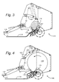
- FIG. 3 is a side elevation view of a round baler with a partially formed bale
- FIG. 4 is a side elevation view of a round baler with a fully formed bale
- FIG. 5 is a rear elevation view of a round baler
- FIG. 6 is a side elevation view of a round baler pulled by an agricultural tractor
- FIG. 7 is a flow diagram of the process of the present invention.
- FIG. 8 is a flow diagram of a calculation for determining a volume averaged moisture content
- FIG. 9 is a flow diagram of a calculation for determining bale dry matter
- FIG. 10 is a plot of bale weight, W, versus fluid relief value pressure, x;
- FIG. 11 is a flow diagram showing how bale weight and fluid relief value pressure histories are used to determine a new relief valve pressure set point
- FIG. 12 is a perspective view of a cylindrical bale with an ID marking
- FIG. 13 is a perspective view of a cylindrical bale and an identifying page
- FIG. 14 is a perspective view of a cylindrical bale with a transmitter attached to the bale wrap
- FIG. 15 shows a length of twine bale wrapping material with transmitters attached at intervals
- FIG. 16 is a schematic diagram of a first bale density pressure relief/control system
- FIG. 17 is a schematic diagram of a second bale density pressure relief/control system
- FIG. 18 is a schematic diagram of a coupling between the belt tensioner and a hydraulic damper
- FIG. 19 is a flow diagram of information to an identifying page.
- FIG. 20 is a flow diagram of information to a transmitter or transponder.
- a cylindrical bale baler 100 is shown in FIGS. 1-6 .
- Crop material 110 feeds into a bale forming chamber 120 where the crop material is rolled into a bale 310 .
- the baler 100 is outfitted with a tongue load cell 130 and axle load cells 510 at each end of the axle 210 . Signals from these load cells are combined to obtain a weight of the bale 310 .
- at least one moisture sensor 140 is provided near a crop material inlet 150 . The moisture sensor 140 provides a signal proportional to the percentage by mass of water in the incoming crop material 110 as follows:
- M Mass ⁇ ⁇ of ⁇ ⁇ water ⁇ ⁇ in ⁇ ⁇ crop ⁇ ⁇ material Total ⁇ ⁇ ⁇ mass ⁇ ⁇ ⁇ of ⁇ ⁇ crop ⁇ ⁇ material
- the baler 100 is shown lifting forage material 110 , inserting it through the inlet 150 , and forming a bale 310 .
- the baler is supported at three points: by right and left side wheels 220 and by a tongue 165 .
- the load cells 510 engaged to the axle 210 are shown in FIG. 5 .
- the tongue load cell 130 is shown in FIGS. 1 , 3 , and 4 .
- the load cells are produced by Digistar® as PN 2.125 DA-21 Drawing no 403993.
- Each load cell 130 , 510 will generate a signal that is proportional to the load supported at that point.
- the generated signal is transferred in any manner to a controller 620 .
- the method of communication illustrated in the present embodiment includes a wire connection via a wiring harness 630 . Wireless communication is an alternative.
- the controller 620 may be mounted on/in the tractor 610 or on the baler 100 .
- the large round baler is shown in perspective from the right rear corner in FIG. 2 .
- the moisture sensor 140 is shown from the inside.
- the right wheel 220 has been removed.
- FIG. 6 illustrates a round baler 100 being towed by a tractor 610 in the normal fashion.
- a flow diagram of the process of gathering bale data is shown in FIG. 7 .
- the bale 310 begins to form 700 by the introduction of crop material 110 into the baler 100 .
- the bale size measured by the diameter, d, increases 705 .
- the baler system senses the diameter, d, 710 .
- the instantaneous diameter, d is compared to a lower threshold diameter, d 0 , in a first comparator block 715 . If the instantaneous diameter, d, is less than the threshold diameter, d 0 , the bale is allowed to continue to grow 705 .
- the instantaneous diameter, d is greater than or equal to the threshold diameter, d 0 , the instantaneous diameter, d, is stored in d 1 720 and moisture readings are begun 725 .
- the bale diameter, d continues to be sensed 730 and at increments of ⁇ d 735 , the bale moisture content is volume averaged 740 (see FIG. 8 ).
- the bale diameter, d is compared to the terminal diameter, d T 745 , at which addition of crop material 110 is to be terminated.
- the bale diameter, d has reached the terminal diameter, d T , the bale 310 is bound 750 , weighed 755 , and ejected 760 .
- Binding can be accomplished in any way known in this art such as twine 1510 (see FIG. 15 ) or netwrap.
- the present invention is not limited to any particular binding method or material. This process will usually be repeated until all the crop material 110 is baled, or until conditions are such that baling should be terminated, as is well known by those skilled in the art.
- Moisture measurement is made possible during baling by the pad 140 on at least one side of a baler as disclosed in U.S. Pat. No. 4,812,741 to Stowell and herein incorporated by reference.
- FIGS. 1-4 and 6 illustrates one such moisture sensor 140 mounted on the left side panel.
- a moisture measurement is received by the controller 620 at intervals in time.
- the moisture content is displayed as a number between zero and one, and is calculated as:
- M n is the n th moisture reading
- d n is the n th diameter
- M n represents the diameter at the time of the n th moisture reading
- the n th moisture reading, M n may be an average of the moisture readings taken while the bale diameter increased from d n ⁇ 1 to d n , or it may be a single, representative reading taken during the growth of the bale from the diameter, d n ⁇ 1 , to the diameter, d n .
- the plot in FIG. 10 shows a set of bale weights plotted against the associated manipulated variable such as a pressure relief valve setting, frequency of intermittent valve opening, or duration of intermittent valve opening.
- manipulated variable such as a pressure relief valve setting, frequency of intermittent valve opening, or duration of intermittent valve opening.
- the fluid manipulated variable set point, x sp calculated by interpolation or extrapolation from bale histories, is used to adjust the manipulated variable through which hydraulic fluid must pass as the belt tensioner 170 rotates with the growth of the bale 310 .
- FIGS. 16 and 17 Systems for varying the resistance to pivoting of the belt tensioner 160 are shown in FIGS. 16 and 17 .
- a hydraulic damper 1610 is connected by its shaft 1620 to the belt tensioner 160 .
- the hydraulic damper 1610 travels in its down direction, and hydraulic fluid passes through a check valve 1630 , which provides little resistance to flow.
- the check valve 1630 disallows flow through itself.
- the hydraulic fluid must pass through an adjustable relief valve 1640 , by which the pressure at a pressure gage or transducer 1650 is limited at an upper value to the relief valve pressure set point, x sp .
- the belt tensioner 160 applies a pressure to the hydraulic damper 1610 .
- the pressure at the pressure gage or transducer 1650 must reach the relief valve pressure set point, x sp .
- a control system to estimate the pressure relief valve setting to achieve the desired bale density applies the algorithm previously described and illustrated in FIGS. 10 and 11 provides adjustment to the relief valve 1640 by any method and means well known by those of ordinary skill in the art.
- a stepper motor 1660 may be used to rotate a spring-force adjustment screw 1670 , the spring force ultimately providing the resistance to flow.
- FIG. 17 A more involved pressure control system is schematically illustrated in FIG. 17 .
- a second pressure relief valve 1710 is provided.
- the second pressure relief valve 1710 has a lower set point than the first pressure relief valve 1640 , and only affects the flow if a solenoid valve 1720 is open.
- the belt tensioner 160 is permitted to rise intermittently by intermittent opening of the solenoid valve 1720 .
- the solenoid valve 1720 is closed, the pressure at the pressure gage or transducer 1650 , is, at most, the value at which the first relief 1640 valve is set.
- the density of the bale may be controlled by the frequency and/or duration of the intermittent opening of the solenoid valve 1720 , and the relief valves 1640 , 1710 do not require adjustability.
- the manipulated variable, x sp , of FIGS. 10 and 11 is represented by a frequency or duration of opening of the solenoid valve 1720 .
- An additional embodiment is realized by measuring a value related to the belt tension in place of the manipulated variable, x sp .
- Such values include hydraulic system pressure, as illustrated in FIGS. 16 and 17 , or a load cell reading, as depicted in FIG. 18 which shows a load cell 1810 arranged to detect a force between the hydraulic damper 1610 and a mounting surface.
- the bale may be provided with an identification number, symbol, transponder or transmitter.
- an ID symbol or alphanumeric series 1210 may be painted or inked onto the outside of the bale wrap 1320 (see FIG. 13 ) on the outside of the bale 310 .
- an identifying page 1310 made of paper, cardstock, plastic, fabric, or other material is inserted beneath the bale wrap 1320 .
- Such an identifying page 1310 may include the following data: GPS location, dry matter content, moisture content, weight, customer, operator, and baling date, as depicted in FIG. 19 .
- the identification may be printed to the ID page 1310 , or a transmitter or transponder may be attached to the page.
- a transmitter or transponder 1410 is shown in FIG. 14 attached to the bale wrap.
- the transmitter or transponder 1410 may have the bale data, such as GPS location, dry matter content, moisture content, weight, customer, operator, and baling date, written to it, as depicted in FIG. 20 , before the bale 310 is ejected from the baler 100 .
- the transmitter or transponder 1410 may only contain a unique ID that is correlated to the data stored in the baler's control system 620 .
- both netwrap and twine 1510 may be manufactured with transmitters or transponders 1410 preattached or predetermined intervals, as shown in FIG. 15 , or the attachment may be done in the baler 100 .
- the term “netwrap” is intended to include all sheet-type wrapping materials including tackified plastic materials and untackified plastic materials.
- the term “bale wrap” as used herein is intended to include sheet-type bale wrapping materials as well as twine. It is intended that these specific and depicted aspects be considered exemplary only, with a true scope and spirit of the invention be indicated by the broad meaning of the following claims.
Landscapes
- Life Sciences & Earth Sciences (AREA)
- Environmental Sciences (AREA)
- Storage Of Harvested Produce (AREA)
Abstract
Description
where Mn is the nth moisture reading, dn is the nth diameter, and represents the diameter at the time of the nth moisture reading, Mn. The nth moisture reading, Mn, may be an average of the moisture readings taken while the bale diameter increased from dn−1 to dn, or it may be a single, representative reading taken during the growth of the bale from the diameter, dn−1, to the diameter, dn.
Dry Matter =W(1−M)
Claims (13)
Priority Applications (3)
| Application Number | Priority Date | Filing Date | Title |
|---|---|---|---|
| US11/460,812 US7703391B2 (en) | 2006-07-28 | 2006-07-28 | Round baler with scale and moisture meter |
| US12/553,373 US20090314067A1 (en) | 2006-07-28 | 2009-09-03 | Method of determining baling conditions in a round baler |
| US13/772,734 US20130160661A1 (en) | 2006-07-28 | 2013-02-21 | Round Baler with Scale and Moisture Meter |
Applications Claiming Priority (1)
| Application Number | Priority Date | Filing Date | Title |
|---|---|---|---|
| US11/460,812 US7703391B2 (en) | 2006-07-28 | 2006-07-28 | Round baler with scale and moisture meter |
Related Child Applications (1)
| Application Number | Title | Priority Date | Filing Date |
|---|---|---|---|
| US12/553,373 Division US20090314067A1 (en) | 2006-07-28 | 2009-09-03 | Method of determining baling conditions in a round baler |
Publications (2)
| Publication Number | Publication Date |
|---|---|
| US20090217827A1 US20090217827A1 (en) | 2009-09-03 |
| US7703391B2 true US7703391B2 (en) | 2010-04-27 |
Family
ID=41012190
Family Applications (3)
| Application Number | Title | Priority Date | Filing Date |
|---|---|---|---|
| US11/460,812 Active 2027-04-27 US7703391B2 (en) | 2006-07-28 | 2006-07-28 | Round baler with scale and moisture meter |
| US12/553,373 Abandoned US20090314067A1 (en) | 2006-07-28 | 2009-09-03 | Method of determining baling conditions in a round baler |
| US13/772,734 Abandoned US20130160661A1 (en) | 2006-07-28 | 2013-02-21 | Round Baler with Scale and Moisture Meter |
Family Applications After (2)
| Application Number | Title | Priority Date | Filing Date |
|---|---|---|---|
| US12/553,373 Abandoned US20090314067A1 (en) | 2006-07-28 | 2009-09-03 | Method of determining baling conditions in a round baler |
| US13/772,734 Abandoned US20130160661A1 (en) | 2006-07-28 | 2013-02-21 | Round Baler with Scale and Moisture Meter |
Country Status (1)
| Country | Link |
|---|---|
| US (3) | US7703391B2 (en) |
Cited By (25)
| Publication number | Priority date | Publication date | Assignee | Title |
|---|---|---|---|---|
| US20100326294A1 (en) * | 2009-06-30 | 2010-12-30 | Smith Kevin M | Belt routing in a round baler |
| US8326563B2 (en) | 2010-10-29 | 2012-12-04 | Deere & Company | Method for determining agricultural bale weight |
| US20140174303A1 (en) * | 2012-12-21 | 2014-06-26 | Cnh America Llc | Weighing round bales |
| US9182269B2 (en) | 2010-10-29 | 2015-11-10 | Deere & Company | Method for determining the weight of an agricultural bale that compensates for un-level terrain and adjusting for the amount of wrapping material used |
| US9192103B2 (en) * | 2010-10-28 | 2015-11-24 | Deere & Company | Method and apparatus for determining fraction of hay at different moisture levels |
| US9267836B2 (en) | 2010-10-29 | 2016-02-23 | Deere & Company | Method for adjusting a tare weight of an agricultural baler to reflect usage of preservative in treating formed bale |
| US20160120129A1 (en) * | 2013-06-03 | 2016-05-05 | Cnh Industrial America Llc | Load Sensor for an Agricultural Baler |
| US20160187185A1 (en) * | 2014-12-24 | 2016-06-30 | Cnh Industrial America Llc | Weighing round bales |
| US9622417B2 (en) | 2015-05-01 | 2017-04-18 | Cnh Industrial America Llc | Tailgate motion adjustment system |
| US9854744B2 (en) | 2014-12-11 | 2018-01-02 | Cnh Industrial America Llc | Adjusting bale density setting based on bale weight and/or moisture |
| US9943036B2 (en) | 2011-05-09 | 2018-04-17 | Cnh Industrial America Llc | Tagger for agricultural baler |
| US10289696B2 (en) | 2016-10-31 | 2019-05-14 | Deere & Company | Yield mapping for an agricultural harvesting machine |
| US10303997B2 (en) | 2017-03-08 | 2019-05-28 | Agco Corporation | Bale identification assembly for binding an identification tag to a bale of agricultural crop material |
| US10492371B2 (en) | 2017-03-08 | 2019-12-03 | Agco Corporation | Identification filament with baler binding material |
| US10925217B2 (en) | 2017-10-02 | 2021-02-23 | Deere & Company | Baler with dry matter content detection system |
| US10945378B2 (en) | 2017-10-02 | 2021-03-16 | Deere & Company | Method of controlling bale size based on bale weight |
| US11051456B2 (en) | 2019-01-02 | 2021-07-06 | Deere & Company | Bale weight measurement and control system using liftgate |
| IT202000001009A1 (en) | 2020-01-20 | 2021-07-20 | Kverneland Group Ravenna Srl | PACKER WITH RAMP SENSOR |
| US11140830B2 (en) | 2019-01-09 | 2021-10-12 | Great Plains Manufacturing, Inc. | High capacity baler with multiple knotters |
| US11751511B2 (en) | 2013-03-15 | 2023-09-12 | Cnh Industrial America Llc | Bale forming control system and method |
| US11771010B2 (en) | 2020-07-20 | 2023-10-03 | Deere & Company | Round baler with position controlled take-up roller, and method of operating a round baler |
| EP4275479A1 (en) * | 2022-05-11 | 2023-11-15 | Usines Claas France S.A.S | Method for operating a round baler and round baler |
| US11825775B2 (en) | 2020-07-20 | 2023-11-28 | Deere & Company | Round baler with bale holder in gate |
| US11974522B2 (en) | 2020-12-23 | 2024-05-07 | Cnh Industrial America Llc | Method and control system for controlling baler power-take-off speed |
| US20250011031A1 (en) * | 2023-07-06 | 2025-01-09 | Cnh Industrial America Llc | System and method for securing a tail on a bale wrap |
Families Citing this family (24)
| Publication number | Priority date | Publication date | Assignee | Title |
|---|---|---|---|---|
| US20120240527A1 (en) * | 2010-12-27 | 2012-09-27 | Agco Corporation | Baler Mesh Wrap Control With Tension Variance |
| US9599544B2 (en) * | 2012-12-21 | 2017-03-21 | Langston Companies Inc. | Method and apparatus for preparing a bale sample from a bale of fibrous material, and a bale sample produced thereby |
| US20140290202A1 (en) * | 2013-03-27 | 2014-10-02 | Deere & Company | Wrap indication device |
| NL2014595B1 (en) | 2015-04-08 | 2017-01-19 | Forage Innovations Bv | Agricultural combination with a scale and a weighing method. |
| NL2015350B1 (en) * | 2015-08-26 | 2017-03-16 | Forage Innovations Bv | Bale forming and wrapping apparatus and method with a wrapping monitoring sensor. |
| US10064339B2 (en) * | 2015-12-02 | 2018-09-04 | Agco Corporation | System and method for controlling bale weight |
| DE102016205626A1 (en) | 2016-04-05 | 2017-10-05 | Deere & Company | Method and arrangement for monitoring organic material in a foil-wrapped bale |
| PL3228180T5 (en) * | 2016-04-05 | 2024-01-15 | Deere & Company | Communication system tracking information related to a baled crop and related method |
| US10436913B2 (en) | 2016-06-09 | 2019-10-08 | Deere & Company | Baler information system and method |
| US20180014467A1 (en) * | 2016-07-12 | 2018-01-18 | Deere & Company | Identification tagging system for harvesting machines and method thereof |
| US10385605B2 (en) * | 2016-11-16 | 2019-08-20 | Vermeer Manufacturing Company | Tailgate sensor |
| US11051454B2 (en) * | 2017-03-08 | 2021-07-06 | Agco Corporation | Identification filament with baler binding material |
| US10980183B2 (en) * | 2017-08-11 | 2021-04-20 | Vermeer Manufacturing Company | Self-propelled vehicles with extendable devices |
| US10687472B2 (en) | 2018-05-09 | 2020-06-23 | Deere & Company | Bale weight measurement device |
| GB201909537D0 (en) * | 2019-07-02 | 2019-08-14 | Kuhn Geldrop Bv | Baler density control |
| CN110488881B (en) * | 2019-08-28 | 2023-08-18 | 合肥微擎信息技术有限公司 | Automatic control method for bale pressure control of baler |
| JP7140736B2 (en) * | 2019-11-07 | 2022-09-21 | 株式会社クボタ | Yield calculation system, yield map generation system, Boehler's yield calculation method, computer program, and computer readable medium |
| EP4084600B1 (en) * | 2019-12-30 | 2024-10-09 | Agco Corporation | Temperature compensation system and method for nir sample on baler |
| EP4124237A1 (en) | 2021-07-30 | 2023-02-01 | CNH Industrial Belgium N.V. | Method for determining a quality of an agricultural bale |
| DE102021123353A1 (en) * | 2021-09-09 | 2023-03-09 | Usines Claas France S.A.S. | Method of operating an agricultural round baler |
| GB202117952D0 (en) * | 2021-12-13 | 2022-01-26 | Agco Int Gmbh | Bale wrapping system |
| CN114402801B (en) * | 2022-01-11 | 2024-01-30 | 中国科学院合肥物质科学研究院 | Ramie harvesting bundling diameter self-adaptive control device and method |
| US20230403981A1 (en) * | 2022-06-21 | 2023-12-21 | Deere & Company | Baler implement and print system for marking a bale |
| DE102023116117A1 (en) * | 2023-06-20 | 2024-12-24 | Pöttinger Landtechnik Gmbh | Agricultural baler and method and device for determining the bale weight of a crop bale formed thereby |
Citations (6)
| Publication number | Priority date | Publication date | Assignee | Title |
|---|---|---|---|---|
| US4812741A (en) | 1987-02-10 | 1989-03-14 | Stowell Dennis E | Baler-mounted continuous moisture monitoring system |
| US4850271A (en) | 1987-09-29 | 1989-07-25 | Hesston Corporation | Round baler having simulated bale size and shape indicator |
| US5622104A (en) | 1995-08-28 | 1997-04-22 | Gehl Company | Cylindrical baler having hydraulic circuit for controlling bale density and tailgate operation |
| US6378276B1 (en) | 1999-02-17 | 2002-04-30 | Lely Welger Maschinenfabrik Gmbh | Baler with a weighing device |
| US6525276B1 (en) | 1998-08-07 | 2003-02-25 | The University Of Georgia Research Foundation, Inc. | Crop yield monitoring system |
| US6530311B1 (en) * | 1998-12-10 | 2003-03-11 | Lely Maschinenfabrik Gmbh | Method of and a bale press for producing high-density round bales from agricultural harvest products |
Family Cites Families (5)
| Publication number | Priority date | Publication date | Assignee | Title |
|---|---|---|---|---|
| US5551218A (en) * | 1994-09-19 | 1996-09-03 | Gehl Company | Round baler monitoring and control system |
| US6431981B1 (en) * | 1999-06-30 | 2002-08-13 | Wisconsin Alumni Research Foundation | Yield monitor for forage crops |
| EP1090543A1 (en) * | 1999-10-05 | 2001-04-11 | Lely Research Holding AG | Device and process for wrapping bodies, especially bales of harvested crops |
| FI110423B (en) * | 2000-04-07 | 2003-01-31 | Wrapmatic Oy | Method and apparatus for wrapping feed bales |
| US6370852B1 (en) * | 2000-10-31 | 2002-04-16 | Deere & Company | Arrangement for the storage of data specific to a bale |
-
2006
- 2006-07-28 US US11/460,812 patent/US7703391B2/en active Active
-
2009
- 2009-09-03 US US12/553,373 patent/US20090314067A1/en not_active Abandoned
-
2013
- 2013-02-21 US US13/772,734 patent/US20130160661A1/en not_active Abandoned
Patent Citations (6)
| Publication number | Priority date | Publication date | Assignee | Title |
|---|---|---|---|---|
| US4812741A (en) | 1987-02-10 | 1989-03-14 | Stowell Dennis E | Baler-mounted continuous moisture monitoring system |
| US4850271A (en) | 1987-09-29 | 1989-07-25 | Hesston Corporation | Round baler having simulated bale size and shape indicator |
| US5622104A (en) | 1995-08-28 | 1997-04-22 | Gehl Company | Cylindrical baler having hydraulic circuit for controlling bale density and tailgate operation |
| US6525276B1 (en) | 1998-08-07 | 2003-02-25 | The University Of Georgia Research Foundation, Inc. | Crop yield monitoring system |
| US6530311B1 (en) * | 1998-12-10 | 2003-03-11 | Lely Maschinenfabrik Gmbh | Method of and a bale press for producing high-density round bales from agricultural harvest products |
| US6378276B1 (en) | 1999-02-17 | 2002-04-30 | Lely Welger Maschinenfabrik Gmbh | Baler with a weighing device |
Non-Patent Citations (2)
| Title |
|---|
| 15 pages entitled Automatic Data Acquisition on Round Balers by K. Wild, et al-1994. |
| 15 pages entitled Automatic Data Acquisition on Round Balers by K. Wild, et al—1994. |
Cited By (42)
| Publication number | Priority date | Publication date | Assignee | Title |
|---|---|---|---|---|
| US8051771B2 (en) * | 2009-06-30 | 2011-11-08 | Cnh America Llc | Belt routing in a round baler |
| US20100326294A1 (en) * | 2009-06-30 | 2010-12-30 | Smith Kevin M | Belt routing in a round baler |
| US9192103B2 (en) * | 2010-10-28 | 2015-11-24 | Deere & Company | Method and apparatus for determining fraction of hay at different moisture levels |
| US8326563B2 (en) | 2010-10-29 | 2012-12-04 | Deere & Company | Method for determining agricultural bale weight |
| US9182269B2 (en) | 2010-10-29 | 2015-11-10 | Deere & Company | Method for determining the weight of an agricultural bale that compensates for un-level terrain and adjusting for the amount of wrapping material used |
| US9267836B2 (en) | 2010-10-29 | 2016-02-23 | Deere & Company | Method for adjusting a tare weight of an agricultural baler to reflect usage of preservative in treating formed bale |
| US9943036B2 (en) | 2011-05-09 | 2018-04-17 | Cnh Industrial America Llc | Tagger for agricultural baler |
| US20140174303A1 (en) * | 2012-12-21 | 2014-06-26 | Cnh America Llc | Weighing round bales |
| US9297688B2 (en) * | 2012-12-21 | 2016-03-29 | Cnh Industrial America Llc | Weighing round bales |
| US9585310B2 (en) | 2012-12-21 | 2017-03-07 | Cnh Industrial America Llc | Weighing round bales |
| US11751511B2 (en) | 2013-03-15 | 2023-09-12 | Cnh Industrial America Llc | Bale forming control system and method |
| US20160120129A1 (en) * | 2013-06-03 | 2016-05-05 | Cnh Industrial America Llc | Load Sensor for an Agricultural Baler |
| US9861041B2 (en) * | 2013-06-03 | 2018-01-09 | Cnh Industrial America Llc | Load sensor for an agricultural baler |
| US9854744B2 (en) | 2014-12-11 | 2018-01-02 | Cnh Industrial America Llc | Adjusting bale density setting based on bale weight and/or moisture |
| US10036663B2 (en) * | 2014-12-24 | 2018-07-31 | Cnh Industrial America Llc | Weighing round bales |
| US20160187185A1 (en) * | 2014-12-24 | 2016-06-30 | Cnh Industrial America Llc | Weighing round bales |
| US9622417B2 (en) | 2015-05-01 | 2017-04-18 | Cnh Industrial America Llc | Tailgate motion adjustment system |
| US10289696B2 (en) | 2016-10-31 | 2019-05-14 | Deere & Company | Yield mapping for an agricultural harvesting machine |
| US10949732B2 (en) | 2017-03-08 | 2021-03-16 | Agco Corporation | Bale identification assembly for binding an identification tag to a bale of agricultural crop material |
| US11361210B2 (en) | 2017-03-08 | 2022-06-14 | Agco Corporation | Assigning an identifying element to a bale |
| US10492371B2 (en) | 2017-03-08 | 2019-12-03 | Agco Corporation | Identification filament with baler binding material |
| US10303997B2 (en) | 2017-03-08 | 2019-05-28 | Agco Corporation | Bale identification assembly for binding an identification tag to a bale of agricultural crop material |
| US10945378B2 (en) | 2017-10-02 | 2021-03-16 | Deere & Company | Method of controlling bale size based on bale weight |
| US10925217B2 (en) | 2017-10-02 | 2021-02-23 | Deere & Company | Baler with dry matter content detection system |
| US11051456B2 (en) | 2019-01-02 | 2021-07-06 | Deere & Company | Bale weight measurement and control system using liftgate |
| US11547055B2 (en) | 2019-01-09 | 2023-01-10 | Great Plains Manufacturing, Inc. | Rotor for a high capacity baler |
| US11825773B2 (en) | 2019-01-09 | 2023-11-28 | Great Plains Manufacturing, Inc. | High capacity baler |
| US11317567B2 (en) | 2019-01-09 | 2022-05-03 | Great Plains Manufacturing, Inc. | Accumulating system for high capacity baler |
| US11140830B2 (en) | 2019-01-09 | 2021-10-12 | Great Plains Manufacturing, Inc. | High capacity baler with multiple knotters |
| US11559002B2 (en) | 2019-01-09 | 2023-01-24 | Great Plains Manufacturing, Inc. | Singulating system for high capacity baler |
| US11576307B2 (en) | 2019-01-09 | 2023-02-14 | Great Plains Manufacturing, Inc. | Bundling system for high capacity baler |
| US11576306B2 (en) | 2019-01-09 | 2023-02-14 | Great Plains Manufacturing, Inc. | Display for high capacity baler |
| US11350571B2 (en) | 2019-01-09 | 2022-06-07 | Great Plains Manufacturing, Inc. | Baler with multiple plungers |
| US20220338418A1 (en) * | 2020-01-20 | 2022-10-27 | Kverneland Group Ravenna S.R.L. | Baler with ramp sensor |
| IT202000001009A1 (en) | 2020-01-20 | 2021-07-20 | Kverneland Group Ravenna Srl | PACKER WITH RAMP SENSOR |
| EP4631347A2 (en) | 2020-01-20 | 2025-10-15 | Kverneland Group Ravenna S.r.l. | Baler with ramp sensor |
| US12178163B2 (en) * | 2020-01-20 | 2024-12-31 | Kverneland Group Ravenna S.R.L. | Baler with ramp sensor |
| US11771010B2 (en) | 2020-07-20 | 2023-10-03 | Deere & Company | Round baler with position controlled take-up roller, and method of operating a round baler |
| US11825775B2 (en) | 2020-07-20 | 2023-11-28 | Deere & Company | Round baler with bale holder in gate |
| US11974522B2 (en) | 2020-12-23 | 2024-05-07 | Cnh Industrial America Llc | Method and control system for controlling baler power-take-off speed |
| EP4275479A1 (en) * | 2022-05-11 | 2023-11-15 | Usines Claas France S.A.S | Method for operating a round baler and round baler |
| US20250011031A1 (en) * | 2023-07-06 | 2025-01-09 | Cnh Industrial America Llc | System and method for securing a tail on a bale wrap |
Also Published As
| Publication number | Publication date |
|---|---|
| US20090314067A1 (en) | 2009-12-24 |
| US20130160661A1 (en) | 2013-06-27 |
| US20090217827A1 (en) | 2009-09-03 |
Similar Documents
| Publication | Publication Date | Title |
|---|---|---|
| US7703391B2 (en) | Round baler with scale and moisture meter | |
| US9854744B2 (en) | Adjusting bale density setting based on bale weight and/or moisture | |
| US5913801A (en) | Agricultural baler, and method of baling | |
| US7331168B2 (en) | Baler | |
| EP2446731B1 (en) | Method for determining weight of an agricultural bale | |
| US7621111B2 (en) | System and method for identifying bales of hay | |
| CN102781221B (en) | A kind of square baling press and relevant control method | |
| EP3315016B1 (en) | Round baler and method of creating a yield map for such a round baler | |
| EP3592133B1 (en) | Bale identification assembly for binding an identification tag to a bale of agricultural crop material | |
| US6378276B1 (en) | Baler with a weighing device | |
| EP2446733B1 (en) | Method for baling and agricultural baler | |
| EP3567350A2 (en) | Improved bale weight measurement device | |
| US9267836B2 (en) | Method for adjusting a tare weight of an agricultural baler to reflect usage of preservative in treating formed bale | |
| US20230032085A1 (en) | Method for determining a quality of an agricultural bale | |
| US11860182B2 (en) | Sensor arrangement for detecting the density of harvested crops in a silo and compaction vehicle provided therewith | |
| US20180295781A1 (en) | Identification filament with baler binding material | |
| US9182269B2 (en) | Method for determining the weight of an agricultural bale that compensates for un-level terrain and adjusting for the amount of wrapping material used | |
| EP3837963B1 (en) | Methods and systems for measuring throughput in agricultural equipment | |
| US20210127589A1 (en) | Identification filament with baler binding material | |
| EP3750397B1 (en) | Agricultural tractor with integrated suspension system for baler application | |
| US20250374864A1 (en) | Bale length variation control system | |
| Kadam | A Load Cell-Free Solution for Weighing |
Legal Events
| Date | Code | Title | Description |
|---|---|---|---|
| AS | Assignment |
Owner name: VERMEER MANUFACTURING COMPANY, IOWA Free format text: ASSIGNMENT OF ASSIGNORS INTEREST;ASSIGNORS:DUENWALD, TOM;REMPE, SCOTT;MEINDERS, CALVIN;REEL/FRAME:018164/0236;SIGNING DATES FROM 20060720 TO 20060724 Owner name: VERMEER MANUFACTURING COMPANY,IOWA Free format text: ASSIGNMENT OF ASSIGNORS INTEREST;ASSIGNORS:DUENWALD, TOM;REMPE, SCOTT;MEINDERS, CALVIN;SIGNING DATES FROM 20060720 TO 20060724;REEL/FRAME:018164/0236 |
|
| STCF | Information on status: patent grant |
Free format text: PATENTED CASE |
|
| FPAY | Fee payment |
Year of fee payment: 4 |
|
| MAFP | Maintenance fee payment |
Free format text: PAYMENT OF MAINTENANCE FEE, 8TH YEAR, LARGE ENTITY (ORIGINAL EVENT CODE: M1552) Year of fee payment: 8 |
|
| MAFP | Maintenance fee payment |
Free format text: PAYMENT OF MAINTENANCE FEE, 12TH YEAR, LARGE ENTITY (ORIGINAL EVENT CODE: M1553); ENTITY STATUS OF PATENT OWNER: LARGE ENTITY Year of fee payment: 12 |