EP3567350A2 - Improved bale weight measurement device - Google Patents
Improved bale weight measurement device Download PDFInfo
- Publication number
- EP3567350A2 EP3567350A2 EP19173357.5A EP19173357A EP3567350A2 EP 3567350 A2 EP3567350 A2 EP 3567350A2 EP 19173357 A EP19173357 A EP 19173357A EP 3567350 A2 EP3567350 A2 EP 3567350A2
- Authority
- EP
- European Patent Office
- Prior art keywords
- axle
- housing
- deflection
- spindle
- bale
- Prior art date
- Legal status (The legal status is an assumption and is not a legal conclusion. Google has not performed a legal analysis and makes no representation as to the accuracy of the status listed.)
- Granted
Links
- 238000005259 measurement Methods 0.000 title description 5
- 238000012545 processing Methods 0.000 claims description 20
- 238000000034 method Methods 0.000 claims description 17
- 238000001514 detection method Methods 0.000 description 5
- 238000005303 weighing Methods 0.000 description 5
- 239000000428 dust Substances 0.000 description 4
- 238000012986 modification Methods 0.000 description 2
- 230000004048 modification Effects 0.000 description 2
- 238000012544 monitoring process Methods 0.000 description 2
- 230000005355 Hall effect Effects 0.000 description 1
- 230000001133 acceleration Effects 0.000 description 1
- 238000013459 approach Methods 0.000 description 1
- 230000004323 axial length Effects 0.000 description 1
- 238000013461 design Methods 0.000 description 1
- 238000011161 development Methods 0.000 description 1
- 230000018109 developmental process Effects 0.000 description 1
- 238000010586 diagram Methods 0.000 description 1
- 230000001939 inductive effect Effects 0.000 description 1
- 230000000977 initiatory effect Effects 0.000 description 1
- 239000000463 material Substances 0.000 description 1
- 230000003287 optical effect Effects 0.000 description 1
- 239000003755 preservative agent Substances 0.000 description 1
- 230000002335 preservative effect Effects 0.000 description 1
- 230000035945 sensitivity Effects 0.000 description 1
Images


Classifications
-
- G—PHYSICS
- G01—MEASURING; TESTING
- G01G—WEIGHING
- G01G17/00—Apparatus for or methods of weighing material of special form or property
-
- A—HUMAN NECESSITIES
- A01—AGRICULTURE; FORESTRY; ANIMAL HUSBANDRY; HUNTING; TRAPPING; FISHING
- A01F—PROCESSING OF HARVESTED PRODUCE; HAY OR STRAW PRESSES; DEVICES FOR STORING AGRICULTURAL OR HORTICULTURAL PRODUCE
- A01F15/00—Baling presses for straw, hay or the like
- A01F15/08—Details
- A01F15/0825—Regulating or controlling density or shape of the bale
- A01F15/0833—Regulating or controlling density or shape of the bale for round balers
-
- A—HUMAN NECESSITIES
- A01—AGRICULTURE; FORESTRY; ANIMAL HUSBANDRY; HUNTING; TRAPPING; FISHING
- A01D—HARVESTING; MOWING
- A01D59/00—Equipment for binding harvested produce
- A01D59/02—Packers
-
- A—HUMAN NECESSITIES
- A01—AGRICULTURE; FORESTRY; ANIMAL HUSBANDRY; HUNTING; TRAPPING; FISHING
- A01F—PROCESSING OF HARVESTED PRODUCE; HAY OR STRAW PRESSES; DEVICES FOR STORING AGRICULTURAL OR HORTICULTURAL PRODUCE
- A01F15/00—Baling presses for straw, hay or the like
- A01F15/08—Details
- A01F15/0875—Discharge devices
- A01F15/0883—Discharge devices for round balers
-
- G—PHYSICS
- G01—MEASURING; TESTING
- G01G—WEIGHING
- G01G19/00—Weighing apparatus or methods adapted for special purposes not provided for in the preceding groups
- G01G19/02—Weighing apparatus or methods adapted for special purposes not provided for in the preceding groups for weighing wheeled or rolling bodies, e.g. vehicles
-
- A—HUMAN NECESSITIES
- A01—AGRICULTURE; FORESTRY; ANIMAL HUSBANDRY; HUNTING; TRAPPING; FISHING
- A01D—HARVESTING; MOWING
- A01D34/00—Mowers; Mowing apparatus of harvesters
- A01D34/006—Control or measuring arrangements
- A01D34/008—Control or measuring arrangements for automated or remotely controlled operation
-
- A—HUMAN NECESSITIES
- A01—AGRICULTURE; FORESTRY; ANIMAL HUSBANDRY; HUNTING; TRAPPING; FISHING
- A01F—PROCESSING OF HARVESTED PRODUCE; HAY OR STRAW PRESSES; DEVICES FOR STORING AGRICULTURAL OR HORTICULTURAL PRODUCE
- A01F15/00—Baling presses for straw, hay or the like
- A01F15/08—Details
- A01F15/0875—Discharge devices
- A01F2015/0891—Weighing the finished bale before falling to ground
Abstract
Description
- The present disclosure relates to a system for determining the weight of a bale and protecting the parts of a baler utilized in bale weighing.
- The weight of a bale is information desired by operators. The information can be used to evaluate the yield in a particular field. In addition, based on pre-stored data or operator experience, the information can indicate a moisture level of the harvested bale. In order to transport multiple bales, summing bales with various weights will help the user to plan loads for transportation within the acceptable maximum weight limits. There is a need for a more accurate bale weight apparatus and system, with the protection for parts of a baler utilized in bale weighing.
- This summary is provided to introduce a selection of concepts that are further described below in the detailed description and accompanying drawings. This summary is not intended to identify key or essential features of the appended claims, nor is it intended to be used as an aid in determining the scope of the appended claims.
- According to an aspect of the present disclosure, a baler for forming a bale includes a frame, an axle, a sensor, and at least one overload stop. The frame supports a bale chamber. The axle is connected to the frame at a first location and spaced apart from the frame at a second location. The sensor is positioned to measure the deflection of the axle. The deflection of the axle changes based upon a weight of the bale. The at least one overload stop is positioned on one of the axle and the frame to limit the deflection of the axle relative to the frame.
- According to an aspect of the present disclosure, a baler for forming a bale includes a frame, axle housing, first and second spindles, first, second, and third sensors, a linkage, and a processing unit. The frame supports a bale chamber. The first spindle is partially surrounded by the axle housing, and is spaced apart from the axle housing. The second spindle is partially surrounded by the axle housing, and is spaced apart from the axle housing. The first sensor is positioned at one of the axle housing and the first spindle, and is configured to detect a first deflection of the first spindle based upon a first distance between the first spindle and the axle housing. The second sensor is positioned at one of the axle housing and the second spindle, and is configured to detect a second deflection of the second spindle based upon a second distance between the second spindle and the axle housing. The linkage is coupled to a front portion of the frame, and is partially surrounded by a linkage housing. The linkage is spaced apart from the linkage housing. The third sensor is coupled to the linkage, and is configured to detect a third deflection of the linkage. The processing unit is connected to the first, second, and third sensors, and is configured to calculate a weight of the bale based upon the the detected first, second, and third deflections. In an embodiment, the baler further comprising a first overload stop protruding from one of the axle housing and the first spindle and a second overload stop protruding from one of the axle housing and the second spindle, wherein a range of the first deflection detected by the first sensor is reduced by the first overload stop and a range of the second deflection detected by the second sensor is reduced by the second overload stop. In another embodiment, the first and second overload stops are fasteners, respectively penetrated through the axle housing. In yet another embodiment, the first and the second overload stop are respectively adjacent to outer ends of axle housing.
- A method of measuring a weight of a baler in a baler may include include determing a first deflection of an axle via a sensor; forming a bale in the baler; detecting a second deflection of the axle via the sensor; comparing the first and second deflections of the axle to calculate the weight of the bale; and limiting the deflection of the axle within a pre-determined amount via an overload stop. In an embodiment, the step of detecting at least one deflection further comprising: detecting a first deflection of the axle based upon a first distance between the axle and an axle housing; and detecting a second deflection of the axle based upon a second distance between the axle and the axle housing. In a further embodiment, the method further comprising: comparing a difference between the first and second distances to calculate the weight of the bale.
- Other features and aspects will become apparent by consideration of the detailed description and accompanying drawings.
- These and other features will become apparent from the following detailed description and accompanying drawings, wherein various features are shown and described by way of illustration. The present disclosure is capable of other and different configurations and its several details are capable of modification in various other respects, all without departing from the scope of the present disclosure. Accordingly, the detailed description and accompanying drawings are to be regarded as illustrative in nature and not as restrictive or limiting.
- The detailed description of the drawings refers to the accompanying figures in which:
-
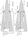
FIG. 1 is a side view of a baler; -
FIG. 2 is a front view of the baler; -
FIG. 3A is an exploded view of an axle housing, an axle, an overload stop, and other components; -
FIG. 3B is an exploded view of the axle housing, the axle, another embodiment of an overlaod stop, and other components; -
FIG. 4A is a cross-sectional view ofFIG. 3A ; -
FIG. 4B is a cross-sectional view of another embodiment of axle housing, axle, and sensor; -
FIG. 4C is a cross-sectional view of another embodiment of a sensor detecting the deflection outside of the axle; -
FIG. 4D is a cross-sectional view of another embodiment of sensor detecting the deflection within the axle; -
FIG. 4E is a cross-sectional view of another embodiment of an overload stop; -
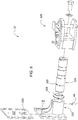
FIG. 5 is a perspective view of a clevis arrangement of a linkage of the baler; -
FIG. 6 is a partial exploded view ofFIG. 5 ; -
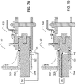
FIG. 7A is a cross-sectional view ofFIG. 5 ; -
FIG. 7B is a cross-sectional view of another embodiment of a clevis arrangement and a sensor of a linkage of the baler; and -
FIG. 8 is a flow diagram illustrating a method of measuring a weight of a bale under one of timing options. - Referring to
FIG. 1 , around baler 10 includes aframe 12 and anaxle housing 20 coupled to theframe 12. Anaxle 22 is coupled to theframe 12,axle housing 20, or both and is partially surrounded by theaxle housing 20. Theframe 12 is supported on a pair of ground engaging devices, such aswheels 14, coupled to theaxle 22. A linkage ordraft tongue 30 is coupled to the frame 12 (or front wall 124) and includes aclevis arrangement 32 adapted for being coupled to a towing vehicle (not shown). - The
frame 12 includes anenclosure 122 formed at least in part by afront wall 124, twoside walls 126, and adischarge gate 128, which pivots vertically about ahorizontal pivot arrangement 127 located at an upper rear location of theside walls 126. A gate cylinder arrangement (not shown) is coupled between theframe 12 andside walls 129 of thedischarge gate 128 and is selectively operable for moving thedischarge gate 128 between a lowered baling position and an opened discharge position. Thedischarge gate 128 remains at the lowered baling position when a bale B is forming and then moves to the opened discharge position when the bale B completes its wrapping process and is at an appropriate place to release the bale B (not shown). - The
baler 10 includes abale forming chamber 123. Thebaler 10 may be a variable or fixed chamber baler. Thebaler 10 includes a plurality of longitudinally extending side-by-side belts 134 supported on a plurality of rollers 132 (only a few of which are shown). The variable or fixedbale forming chamber 123 is defined by theside walls rollers 132 and thebelts 134. - The
baler 10 as illustrated is a variable chamber design, wherein crop is rolled up in a spiral fashion in a nip formed between oppositely moving adjacent loops ofbelts 134. When thebaler 10 moves across the ground and a supplyingdevice 16 of baler keeps conveying the crops from the ground, the space between adjacent loops ofbelts 134 grows as the forming bale B grows larger. Accordingly, abelt tensioning device 136 is provided to take up slack in thebelts 134 as needed. Thus the position of thetensioning device 136, at any given time, is an indication of the size of the bale B at that time. A bale diameter sensor (not shown) in the form of a potentiometer is affixed to the pivot point of thetensioning device 136 and thus provides an electrical signal correlating with bale diameter to an processing unit or Electronic Control Unit (ECU) 50. Theprocessing unit 50 is provided for electronically controlling and monitoring a number of functions of thebaler 10. For example, theprocessing unit 50 in addition to monitoring bale size and other functions, can further be adapted for triggering a twine or wrapping cycle, opening the discharge gate, initiating bale discharge, controlling the application of preservative to the bate and for communicating crop moisture content and other information to the user. In addition, theprocessing unit 50 may be used for determining the weight of a bale as described in more detail below. - Referring to
FIGS. 1 and2 , theaxle housing 20, in this embodiment, includes afirst housing 24 and asecond housing 26 positioned opposite to one another. Theaxle 22 includes afirst spindle 222 and asecond spindle 226. Thefirst spindle 222 is partially surrounded by thefirst housing 24 and thesecond spindle 226 partially surrounded by thesecond housing 26. Theclevis arrangement 32 includes ahitch housing 322 and ahitch rod 324 surrounded by thehitch housing 322. Thebaler 10 further includes multiple sensors 40 (will be shown inFIGS. 3A-7B ), including a first sensor 42, a second sensor 44, and athird sensor 46. In this embodiment, the multiple sensors 40 detect or measure a space or gap between the first andsecond spindles second housings hitch housing 322 and thehitch rod 324. The sensors 40 may be optical, inductive, hall effect, and/or other means of sensors. The sensors 40 may not only used for detecting distance that may reflect to deflections of spindles or hitch rod, but the sensors may be used for detecting the deflection indirectly, or directly, such as strain gages (load cells). Detail structures of axle housing, axle, and sensors will be delineated in later description. It is noted that the number and the location of the sensors are shown and described by way of illustration, the sensors may also be applied to just one of spindle housing/spindle, one spindle housing/spindle and one hitch housing/hitch rod, or any other configurations. -
FIGS. 4A and 4B demonstrate sensors that measure the distances changed between the spindles and housing to obtain the deflection of the spindles. Referring toFIGS. 3A and4A , in this embodiment, thefirst spindle 222 and thesecond spindle 226 are symmetric to each other, and thefirst housing 24 and thesecond housing 26 are symmetric to each other, so these two sets are shown with reference numbers adjacent to each other. - The
first housing 24 has a first connecting portion 242, a first inner surface 244, and a first opening 246. The first connecting portion 242 extends radially at one end (inner end) of thefirst housing 24 to form a substantially square shape with an opening at the center for thefirst spindle 222 to insert into thefirst housing 24. Adjacent to the four corners of the first connecting portion 242 are four apertures for fasteners or other means to fix thefirst housing 24 on theframe 12. Thefirst spindle 222 is partially surrounded by the first inner surface 244. Thefirst spindle 222 is connected to thefirst housing 24 at a first location L1 and spaced apart from thefirst housing 24 at a second location L2. At the second location L2, a portion of thefirst spindle 222 can extend radially outward more than adjacent portions of the spindle. The first andsecond spindles spindles first housing 24. The first inner surface radially protrudes a pair of first mounting platforms 245 (only shown one of the first mounting platforms inFIG. 3A ). - An outer portion of the
first spindle 222 passes through the first opening 246 and is coupled to one of theground engaging wheels 14. Thefirst spindle 222 includes a first groove 223 adjacent to the inner end of thefirst spindle 222. The bottom of the first groove 223 may include multiple edges 224. Thebaler 10 further includes a first mounting plate 23 having multiple edges 232. A portion of the first mounting plate 23 is inserted into the first groove 223, with the corresponding edges 224, 232 contacting each other to limit the movement between the first mounting plate 23 and thefirst spindle 222. The first mounting plate 23 is coupled to the first mounting platforms via fasteners or other means. - A first distance or first radial deflection gap d1 is between the
first spindle 222 and thefirst housing 24. Because of the weight of thebaler 10, with or without the bale B, thefirst spindle 222 deflects in different degrees and therefore the first distance d1 is related to the weight of thebaler 10 and bale B. In the embodiment shown inFIGS. 3A ,4A , the first sensor 42 is positioned in the first housing to detect the first distance d1. Alternatively,FIG. 4B demonstrates a cross-sectional view of another embodiment of the axle housing, axle, and sensor. In this embodiment, the first sensor 42 is positioned within thefirst spindle 222 to detect the first distance d1. BecauseFIGS. 4A, 4B demonstrate the first sensor 42 positioned at lower portion adjacent to the first opening 246 offirst housing 24 orfirst spindle 222, if the load of the baler increases, the first distance d1 detected by the first sensor 42 will increase until the upper portions adjacent to the first opening 246 of the first housing 24 (or anoverload stop 28 discussed later) andfirst spindle 222 contact. Alternatively, if the first sensor 42 is positioned at upper portion adjacent to the first opening 246 of thefirst housing 24 or first spindle 222 (not shown) and if the load of the baler increases, the first distance d1 detected by the first sensor 42 will decrease until the upper portions adjacent to the first opening 246 of the first housing 24 (or anoverload stop 28 discussed in more detail below) andfirst spindle 222 contact. It is noted that this embodiment illustrates the distance between thefirst spindle 222 and thefirst housing 24 reflecting a deflection of the thefirst spindle 222 is merely an example. The deflection may include any other kinds of formats. - The detected results will be transmitted to the
processing unit 50 to calculate the weight of the bale B. Theprocessing unit 50 may utilize the deflections of thefirst spindle 222 when the bale B is still in thebaler 10, cross-referencing a pre-stored calibration data to determine the weight of the bale B. Or alternatively, when the bale B is still in thebaler 10, theprocessing unit 50 may receive the deflection information of thefirst spindle 222 to determine the total weight of thebaler 10 and the bale B. After the bale B is discharged from thebaler 10, then theprocessing unit 50 may receive the deflection information of thespindle 222 to determine the weight of thebaler 10. The weight of the bale B which had been just discharged will be calculated by comparing the weights of thebaler 10 with and without the bale B. In regards to the information from other sensors such as the second sensor 44 and thethird sensor 46, theprocessing unit 50 may utilize either approach to determine the weight of the bale B. Theprocessing unit 50 may utilize the output or measurements of the one or more first, second, andthird sensors 42, 44, 46 to determine the weight of thebaler 10 and the bale B. In one embodiment, theprocessing unit 50 utilizes the measurements of all threesensors 42, 44, 46 to determine the weight of thebaler 10 with the bale B and the weight of theempty baler 10 without the bale B. -
FIGS. 4C and 4D illustrates sensors that measure the deflections of the spindles. Refering to 4C, the first sensor 42, for example, a load cell attaches to an external surface of thespindle 222. The first sensor 42 can be positioned between the first location L1 and the second location L2, including the second location L2. - Referring to 4D, in this embodiment, the first sensor 42 is an internal sensor positioned within the
spindle 222. The first sensor 42 is configured to measure the deflection of thespindle 222 or indirectly measure an object (shown in dash line) which deflects together with thespindle 222. - Optionally, at least an
overload stop 28, such as a fastener in the embodiments shown inFIGS. 4A-4B , protrudes or extends from the first inner surface 244 toward thefirst spindle 222. Accordingly, a range of the first distance d1 detected by the first sensor 42 is reduced because the overload stop 28 limits the deflection of thefirst spindle 222 and prevents thefirst spindle 222 from contacting the upper portion adjacent to the first opening 246 of thefirst housing 24. There are many circumstances that theoverload stop 28 is utilized to limit such deflection, including but not limited to (1) crops that have more density such that thefirst spindle 222 deflects to contact thefirst housing 24 even before the baling is completed; (2) crops that may have more moister such that thefirst spindle 222 deflects to contact thefirst housing 24 even before the baling is completed; (3) when thebaler 10 is moving or traveling, a sudden acceleration or brake may cause thefirst spindle 222 and thefirst housing 24 quickly approaching to one another; and (4) when thebaler 10 is moving or traveling, a bumping road condition that may cause thebaler 10 move suddenly; and (5) when thebaler 10 is moving or traveling on a ramp. The overload stop prevents the spindle of the axle from mechanical fatigue. It is noted that the limitation of the deflection of thefirst spindle 222 is adjustable via rotating the fastener, for example. In addition, the number of the overload stop 28 can vary. Multiple overload stops can protrude or extend from one of thefirst spindle 222 andfirst housing 24. The multiple overload stops may be positioned surround thespindle 222 to provide 360 degrees protection from mechanical fatigue. Alternatively, the overload stop 28 can be a ring shape as shown inFIGS. 3B and4E . Theoverload stop 28 can be a ring shape element attaching either on thefirst housing 24 orfirst spindle 222, or it protrudes or extrends from either thefirst housing 24 or thefirst spindle 222 and is spaced apart from the other to allow a limited deflection of the spindle. - Referring to
FIGS. 4C-4D , the overload stop 28 and the variation thereof, may be similar to the overload stop(s) described above. The overload stop(s) may also protect the first sensor 42 such as load cells. The load cells in this embodiment are strain-gage load cells. With the development of strain-gage load cells, it is available to measure very small strain, expressed by the unit of microstrain (µε). The strain-gage load cells with high sensitivity (high gage factor, GF) may be proned to be damaged when the spindles they attached deflect beyond a durable range. Therefore, the overload stop(s) 28 limiting the deflection of thefirst spindle 222 may also help prolong the life of the first sensor 42, in this embodiment. - Optionally, a first seal 248 is positioned at the outer end of the
first housing 24 and thefirst spindle 222. The first seal 248 is coupled to the first opening 246 and the first spindle 222.The first seal 248 prevents dust or other objects from entering into the first opening 246. In this regard, dust or other objects will not influence the accuracy of the detection and the weight of the bale B can be calculated more accurately. - In this embodiment, because the
first spindle 222 and thesecond spindle 226 are symmetric to each other, and thefirst housing 24 and thesecond housing 26 are symmetric to each other, reference numbers of second set, including thesecond spindle 226, second groove 227, edge 228, second mounting plate 25, edge 252,second housing 26, second connecting portion 262, second inner surface 264, second mounting platform 265, second opening 266, second seal 268, second distance or second radial deflection gap d2, second sensor 44, are illustrated inFIGS. 3A ,4A-4D and adjacent to the corresponding reference numbers of the first set. There is no description for the second set. - Referring to
FIGS. 5 ,6 , as previously described, theclevis arrangement 32 includes the hitch housing (linkage housing) 322 and the hitch rod (shaft) 324 partially surrounded by thehitch housing 322. When assembled, the front/forward end (right end shown inFIGS. 5 ,6 ) and rear end (left end shown inFIGS. 5 ,6 ) of thehitch rod 324 are outside thehitch housing 322. The front end of thehitch rod 324 is located within theclevis 326. A portion adjacent to the rear end of thehitch rod 324 includesmultiple edges 325 on its surface. Theclevis arrangement 32 further includes alocking plate 327 affixed to the rear end of thehitch housing 322 via at least one nut and bolt. The lockingplate 327 is coupled to thehitch rod 324. The lockingplate 327 includesmultiple edges 329, the number and shape of which are corresponding to those of theedges 325 of thehitch rod 324. Due to the engaged relationship between theedges 325 of thehitch rod 324 and theedges 329 of thelocking plate 327, the movement between lockingplate 327 and thehitch rod 324 is limited. - With reference to
FIGS. 5 ,6 ,7A , a third distance or linkage gap d3 is between thehitch housing 322 and thehitch rod 324. Because of the weight of thebaler 10, with the forming bale B, finished bale B or without the bale B, thehitch rod 324 deflects in different degrees and therefore the third distance d3 is related to the weight of thebaler 10 and the bale B. In the embodiment shown inFIGS. 5 ,6 ,7A , thethird sensor 46 is positioned in thehitch housing 324 to detect the third distance d3. Alternatively,FIG. 7B demonstrates a cross-sectional view of a clevis arrangement and sensor of a linkage of the baler. In this embodiment, thethird sensor 46 is positioned at thehitch rod 324 to detect the third distance d3. It is noted that thethird sensor 46 may also be located at different positions such as a tractor drawbar, tongue weldment, or frame. It is noted that this embodiment illustrates the third distance between thehitch housing 322 and thehitch rod 324 reflecting a deflection of thehitch rod 324 is merely an example. Alternatively, thethird sensor 46 can also be a strain-gage load cell. - In this embodiment, the
processing unit 50 receives the deflection information from each of the individual sensors 40 including the first sensor 42, second sensor 44, andthird sensor 46. The weight of the bale will be determined via theprocessing unit 50 by using the deflection measurements. In this regard, the measurement of the bale weight is more accurate by measuring the deflection of one or more weight bearing members within a structurally acceptable range of deflection for the member. - Optionally, a
third seal 328 is coupled to thehitch housing 322 and thehitch rod 324. Thethird seal 328 prevents dust or other objects from entering into the opening space between thehitch housing 322 and thehitch rod 324. In this regard, dust or other debris does not influence the accuracy of the detection and the weight of the bale B is calculated more accurately. - With reference to
FIG. 8 , a method of measuring a weight of a bale is introduced. -
Step 1 includes forming a bale in the baler. -
Step 2 may include selecting two timing options-option (a) and option (b)-to weighing process/deflection gap (distance) detection. It is noted that this embodiment illustrates the deflection gap/distance applied to the deflection of axle(s) is only for demonstration. The deflection may include any other kinds of formats. - Option (a) includes performing the weighing process/deflection gap detection before the bale is ejected/discharged. The baler is stationary with only minimal movement noise from belts and bale turning. For accuracy, this process may be performed when the discharge gate is closed. Alternatively, this process can be performed when the discharge gate is open.
- Option (b) includes performing the weighing process/deflection gap detection before the bale is ejected/discharged and after the bale is discharged with the discharge gate closed. Alternatively, this process can be performed when the discharge gate is open.
- Step 3 (a) includes detecting load from one or more sensor. The step may include detecting at least one deflection gap that reflects the deflection of an axle from one or more sensors. In step 3 (a), the at least one deflection gap is detected once during the wrapping process. Step 3 (a) includes detecting at least one radial deflection gap between the axle and an axle housing surrounding the axle via at least one sensor when the bale is forming or formed. In this embodiment, the axle includes a first and second spindles; the axle housing includes a first housing and a second housing. The at least one radial deflection gap includes a first radial deflection gap (first distance) between the first spindle and a first housing and a second radial deflection gap (second distance) between a second spindle and a second housing.
- Step 3 (b) includes detecting load from one or more sensor. This step may include detecting at least one deflection gap from one or more sensors. In step 3 (b), the least one deflection gap is detected twice-once during the wrapping process (or the wrapping process is completed) and once after the wrapped bale is discharged. In this embodiment, the weight of the baler with the bale distributed among the first spindle, second spindle, and hitch to cause deflections of those three elements and the deflection gaps between those three elements and their housings are changed and detected by the sensors. There are multiple factors influencing the amount of deflection, including the locations of fulcrums, the length of the arms that forces applied, the Young's modulus of those three elements, the positions of those three elements, whether the baler is moving or performing its function like wrapping. Those factors may have corresponding values of parameters that will be utilized by the processing unit in later step.
- Step 4 (a) includes loads comparision between prestored load and detected load. The step may include comparing the at least one deflection gap with other information to calculate the weight of the bale. Step 4 (a) includes comparing the at least one deflection gap detected before the bale is discharged with pre-stored deflection gap information, with reference to other pre-stored values of parameters for calibration, to determine the weight of the bale via the processing unit. The pre-stored information may include various material properties of the deflecting members, including information necessary to convert the deflection of the members to a force or weight. The pre-stored information may include the weight of the baler without the bale (empty weight).
- Step 4 (b) includes loads comparision between two detected loads. The step may include comparing the at least one deflection gap detected before the bale is discharged with the deflection gap detected after the bale is discharged to determine the weight of the bale via the processing unit.
- In order to prevent the axle from over deflecting,
Step 3 may include limiting changes in deflections in a pre-determining deflection via overload stops protruding from the axle housing toward the axle and/or protruding from the hitch housing toward the hitch rod. - The terminology used herein is for the purpose of describing particular embodiments or implementations and is not intended to be limiting of the disclosure. As used herein, the singular forms "a", "an" and "the" are intended to include the plural forms as well, unless the context clearly indicates otherwise. It will be further understood that the any use of the terms "has," "have," "having," "include," "includes," "including," "comprise," "comprises," "comprising," or the like, in this specification, identifies the presence of stated features, integers, steps, operations, elements, and/or components, but does not preclude the presence or addition of one or more other features, integers, steps, operations, elements, components, and/or groups thereof.
- One or more of the steps or operations in any of the methods, processes, or systems discussed herein may be omitted, repeated, or re-ordered and are within the scope of the present disclosure.
- While the above describes example embodiments of the present disclosure, these descriptions should not be viewed in a restrictive or limiting sense. Rather, there are several variations and modifications which may be made without departing from the scope of the appended claims.
Claims (15)
- A baler for forming a bale (B), comprising:a frame (12) supporting a bale chamber (123);an axle (22) connected to the frame (12) at a first location (L1) and spaced apart from the frame (12) at a second location (L2);a sensor (40, 42, 44, 46) positioned to measure the deflection of the axle (22), the deflection of the axle (22) changing based upon a weight of the bale (B); andat least one overload stop positioned on one of the axle (22) and the frame (12) to limit the deflection of the axle (22) relative to the frame (12).
- The baler of claim 1, wherein the frame (12) comprises a housing (20, 24, 26) at least partially surrounding the axle (22), the sensor (40, 42, 44, 46) positioned to detect a change in distance between the axle (22) and the housing (20, 24, 26) due to the deflection of the axle (22).
- The baler of claim 1 or 2, wherein the housing (20, 24, 26) surrounds the axle (22) and at least partially encloses the sensor (40, 42, 44, 46).
- The baler according to at least one of the preceding claims, wherein the housing (20, 24, 26) comprises a seal (248, 268, 328) positioned at the interface between the housing (20, 24, 26) and the axle (22) enclosing the sensor (40, 42, 44, 46) and a portion of the axle (22).
- The baler according to at least one of the preceding claims, comprising:a housing (20, 24, 26) at least partially surrounding the axle (22); anda first overload stop (28) protruding from one of the housing (20, 24, 26) and the axle (22) and a second overload stop (28) protruding from one of the housing (20, 24, 26) and the axle (22), the first and second overload stops (28) spaced apart and respectively positioned on one end of the axle (22), wherein a range of the first deflection detected by a first sensor (42) is reduced by the first overload stop (28) and a range of the second deflection detected by a second sensor (44) is reduced by the second overload stop (28).
- The baler according to at least one of the preceding claims, wherein the axle (22) includes a portion at the second location (L2) which extends radially outward more than an adjacent portion of the axle (22).
- The baler according to at least one of the preceding claims, wherein the axle (22) comprises a spindle (222, 226) fixedly attached to the frame (12) and operatively connected to a ground engaging device.
- The baler according to at least one of the preceding claims, further comprising:
a processing unit (50) operatively connected to the sensor (40, 42, 44, 46) and configured to calculate a weight of the bale (B) based upon changes in the deflection of the axle (22) as measured by the sensor (40, 42, 44, 46). - The baler according to at least one of the preceding claims, further comprising at least one mounting plate (23, 25), wherein an inner surface (244, 264) of the housing (20, 24, 26) radially protrudes at least one mounting platform (245, 265), the axle (22) includes a groove (223), a portion of the mounting plate (23, 25) inserted into the groove (223) of the axle (22) and the mounting plate (23, 25) is coupled to the at least one mounting platform (245, 265).
- The baler according to at least one of the preceding claims, wherein the bottom of the groove (223) includes multiple first edges, the at least one mounting plate (23, 25) includes multiple second edges, the first edges and second edges contact to one another to limit the mounting plate (23, 25) moving relative to the axle (22).
- The baler according to at least one of the preceding claims, wherein the at least one overload stop is a ring shape.
- A baler for forming a bale (B), comprising:a frame (12) supporting a bale chamber (123);an axle housing (20, 24, 26);a first spindle (222) partially surrounded by the axle housing (20, 24), the first spindle (222) spaced apart from the axle housing (20, 24);a second spindle (226) partially surrounded by the axle housing (20, 26), the second spindle (226) spaced apart from the axle housing (20, 26);a first sensor (42) positioned at one of the axle housing (20, 24, 26) and the first spindle (222), configured to detect a first deflection of the first spindle (222) based upon a first distance between the first spindle (222) and the axle housing (20, 24, 26);a second sensor (44) positioned at one of the axle housing (20, 24, 26) and the second spindle (226), configured to detect a second deflection of the second spindle (226) based upon a second distance between the second spindle (226) and the axle housing (20, 24, 26);a linkage coupled to a front portion of the frame (12), the linkage partially surrounded by a linkage housing (322), the linkage spaced apart from the linkage housing (322);a third sensor (46) coupled to the linkage and configured to detect a third deflection of the linkage; anda processing unit (50) connected to the first, second, and third sensors (40, 42, 44, 46), and configured to calculate a weight of the bale (B) based upon the the detected first, second, and third deflections.
- The baler of claim 12, wherein the linkage includes a shaft (324) partially surrounded by the linkage housing (322), and the third deflection is based upon a third distance between the shaft (324) and the linkage housing (322).
- The baler of claim 12 or 13, wherein the linkage includes a clevis (326), the end of the shaft (324) is located within the clevis (326).
- A method of measuring a weight of a bale (B) in a baler (10), comprising:determing a first deflection of an axle (22) via a sensor (40, 42, 44, 46);forming a bale (B) in the baler (10);detecting a second deflection of the axle (22) via the sensor (40, 42, 44, 46);comparing the first and second deflections of the axle (22) to calculate the weight of the bale; andlimiting the deflection of the axle (22) within a pre-determed amount via an overload stop (28).
Applications Claiming Priority (1)
| Application Number | Priority Date | Filing Date | Title |
|---|---|---|---|
| US15/975,171 US10687472B2 (en) | 2018-05-09 | 2018-05-09 | Bale weight measurement device |
Publications (3)
| Publication Number | Publication Date |
|---|---|
| EP3567350A2 true EP3567350A2 (en) | 2019-11-13 |
| EP3567350A3 EP3567350A3 (en) | 2020-02-26 |
| EP3567350B1 EP3567350B1 (en) | 2022-02-23 |
Family
ID=66542021
Family Applications (1)
| Application Number | Title | Priority Date | Filing Date |
|---|---|---|---|
| EP19173357.5A Active EP3567350B1 (en) | 2018-05-09 | 2019-05-08 | Improved bale weight measurement device |
Country Status (3)
| Country | Link |
|---|---|
| US (2) | US10687472B2 (en) |
| EP (1) | EP3567350B1 (en) |
| BR (1) | BR102019005626B1 (en) |
Families Citing this family (3)
| Publication number | Priority date | Publication date | Assignee | Title |
|---|---|---|---|---|
| US10980183B2 (en) * | 2017-08-11 | 2021-04-20 | Vermeer Manufacturing Company | Self-propelled vehicles with extendable devices |
| US11134614B2 (en) * | 2018-10-10 | 2021-10-05 | Deere & Company | Productivity increase for a round baler |
| US11519776B2 (en) * | 2019-06-13 | 2022-12-06 | Dana Heavy Vehicle Systems Group, Llc | System and method for determining axle load |
Family Cites Families (32)
| Publication number | Priority date | Publication date | Assignee | Title |
|---|---|---|---|---|
| US3780817A (en) * | 1969-02-28 | 1973-12-25 | J Videon | Weighing devices |
| US3650340A (en) * | 1969-07-02 | 1972-03-21 | Art S Way Mfg Co Inc | Strain gage weighing device |
| GB1461396A (en) * | 1973-03-20 | 1977-01-13 | Simms Group Research Dev Ltd | Vehicle axle including load indicating device |
| US3878908A (en) * | 1974-03-05 | 1975-04-22 | Asea Ab | Means for measuring the axle load in vehicles |
| US4123933A (en) * | 1978-01-27 | 1978-11-07 | Towmotor Corporation | Method for measuring axle deflection |
| US4258540A (en) | 1978-05-31 | 1981-03-31 | Sperry Corporation | Agricultural baler |
| US4287958A (en) * | 1979-10-12 | 1981-09-08 | General Trailer Company, Inc. | Vehicle suspension with flexible transversal beam |
| US4362097A (en) | 1980-12-29 | 1982-12-07 | Rogers Laurence J D | Apparatus for determining weight of cylindrical hay bales |
| GB8333679D0 (en) * | 1983-12-17 | 1984-01-25 | Trw Probe Electronics Co Ltd | Strain gauge assemblies |
| JPH08313332A (en) * | 1995-05-24 | 1996-11-29 | Yazaki Corp | Installation structure of sensing element for measuring vehicle load |
| DE19543343C5 (en) * | 1995-11-22 | 2007-01-18 | Claas Kgaa Mbh | Agricultural Baler |
| US6037550A (en) * | 1997-09-30 | 2000-03-14 | Weigh-Tronix, Inc. | On-board vehicle weighing apparatus and method |
| DE19835166C2 (en) | 1998-08-04 | 2000-06-15 | Case Harvesting Sys Gmbh | Method and device for determining the baling density of bales |
| DE19906611A1 (en) * | 1999-02-17 | 2000-08-24 | Lely Welger Maschinenfabrik Gm | Agricultural baler with a weighing device |
| JP3675710B2 (en) * | 2000-10-27 | 2005-07-27 | 矢崎総業株式会社 | Sensing element fixing structure |
| DE10132692C2 (en) * | 2001-07-05 | 2003-11-13 | Siemens Ag | Device for measuring the axle load of a motor vehicle |
| US7254896B2 (en) * | 2002-03-18 | 2007-08-14 | Ensco, Inc. | Inner bearing split axle assembly |
| DE10241215A1 (en) | 2002-09-06 | 2004-03-18 | Deere & Company, Moline | Round baler with weighing device |
| US7507917B2 (en) * | 2004-08-25 | 2009-03-24 | Kaltenheuser Steven R | Apparatus and method for weighing crop on board a harvester |
| US20090048790A1 (en) * | 2006-03-10 | 2009-02-19 | Thomas Dermot Geraghty | System for Determining a Vehicle Load |
| US7703391B2 (en) | 2006-07-28 | 2010-04-27 | Vermeer Manufacturing Company | Round baler with scale and moisture meter |
| GB2449902A (en) * | 2007-06-07 | 2008-12-10 | Cnh Belgium Nv | Weighing apparatus |
| US9267836B2 (en) | 2010-10-29 | 2016-02-23 | Deere & Company | Method for adjusting a tare weight of an agricultural baler to reflect usage of preservative in treating formed bale |
| US9182269B2 (en) * | 2010-10-29 | 2015-11-10 | Deere & Company | Method for determining the weight of an agricultural bale that compensates for un-level terrain and adjusting for the amount of wrapping material used |
| US8326563B2 (en) | 2010-10-29 | 2012-12-04 | Deere & Company | Method for determining agricultural bale weight |
| US9297688B2 (en) | 2012-12-21 | 2016-03-29 | Cnh Industrial America Llc | Weighing round bales |
| US8987615B2 (en) * | 2013-02-27 | 2015-03-24 | American Axle & Manufacturing, Inc. | Axle load monitoring system (ALMS) |
| ES2864593T3 (en) * | 2013-04-08 | 2021-10-14 | Vishay Advanced Tech Ltd | Load sensing device |
| BE1021151B1 (en) | 2013-06-03 | 2016-01-12 | Cnh Industrial Belgium Nv | TAX SENSOR FOR A BALEN PRESS FOR USE IN AGRICULTURE |
| US10289696B2 (en) * | 2016-10-31 | 2019-05-14 | Deere & Company | Yield mapping for an agricultural harvesting machine |
| IT201700093581A1 (en) * | 2017-08-11 | 2019-02-11 | Kverneland Group Ravenna Srl | CONNECTING PACKER WITH A TRACTOR TO CREATE ROUND BALES AND METHOD FOR WEIGHING A ROUND BALL IN A PACKAGER |
| DE102017215438A1 (en) | 2017-09-04 | 2019-03-07 | Deere & Company | Weighing device and harvesting device |
-
2018
- 2018-05-09 US US15/975,171 patent/US10687472B2/en active Active
-
2019
- 2019-03-21 BR BR102019005626-6A patent/BR102019005626B1/en active IP Right Grant
- 2019-05-08 EP EP19173357.5A patent/EP3567350B1/en active Active
-
2020
- 2020-03-11 US US16/815,924 patent/US11129333B2/en active Active
Also Published As
| Publication number | Publication date |
|---|---|
| US20200205349A1 (en) | 2020-07-02 |
| US10687472B2 (en) | 2020-06-23 |
| EP3567350B1 (en) | 2022-02-23 |
| EP3567350A3 (en) | 2020-02-26 |
| US11129333B2 (en) | 2021-09-28 |
| US20190343052A1 (en) | 2019-11-14 |
| BR102019005626B1 (en) | 2023-12-05 |
| BR102019005626A2 (en) | 2019-11-26 |
Similar Documents
| Publication | Publication Date | Title |
|---|---|---|
| US11129333B2 (en) | Bale weight measurement device | |
| US5913801A (en) | Agricultural baler, and method of baling | |
| AU2017200593B2 (en) | Methods, systems, and apparatus for monitoring yield and vehicle weight | |
| CA2439869C (en) | Large round baler with weighing arrangement | |
| US7584696B2 (en) | Agricultural balers | |
| US7331168B2 (en) | Baler | |
| EP2027764B1 (en) | A baler with automatic sensor calibration | |
| US8141480B2 (en) | Automatic bale size calibration on round balers | |
| US4362097A (en) | Apparatus for determining weight of cylindrical hay bales | |
| US20060048654A1 (en) | Rotary baler | |
| US20130160661A1 (en) | Round Baler with Scale and Moisture Meter | |
| EP2446731B1 (en) | Method for determining weight of an agricultural bale | |
| US9267836B2 (en) | Method for adjusting a tare weight of an agricultural baler to reflect usage of preservative in treating formed bale | |
| US7166808B2 (en) | Apparatus for measuring the weight force of a load processed by a machine | |
| US10806091B2 (en) | Weighing device and harvest collecting apparatus | |
| US9182269B2 (en) | Method for determining the weight of an agricultural bale that compensates for un-level terrain and adjusting for the amount of wrapping material used | |
| EP3942921B1 (en) | Round baler with bale holder in gate | |
| US8516957B1 (en) | Measuring distance for bale size in a round baler | |
| US6232565B1 (en) | Bale-weighing system for mobile baling press | |
| Wild et al. | A weighing system for local yield monitoring of forage crops in round balers | |
| EP3440925A1 (en) | Baler connectable to a tractor for providing round bales and method for weighing a round bale in a baler | |
| CZ19754U1 (en) | Circuit arrangement of sensors for detecting throughput rate of forage in round-bale machine provided with variable press chamber | |
| Maguire et al. | Hay and forage measurement for mapping | |
| CZ19988U1 (en) | Circuit arrangement of sensors for detecting forage throughput rate in a baler for making rectangular bales |
Legal Events
| Date | Code | Title | Description |
|---|---|---|---|
| PUAI | Public reference made under article 153(3) epc to a published international application that has entered the european phase |
Free format text: ORIGINAL CODE: 0009012 |
|
| STAA | Information on the status of an ep patent application or granted ep patent |
Free format text: STATUS: THE APPLICATION HAS BEEN PUBLISHED |
|
| AK | Designated contracting states |
Kind code of ref document: A2 Designated state(s): AL AT BE BG CH CY CZ DE DK EE ES FI FR GB GR HR HU IE IS IT LI LT LU LV MC MK MT NL NO PL PT RO RS SE SI SK SM TR |
|
| AX | Request for extension of the european patent |
Extension state: BA ME |
|
| PUAL | Search report despatched |
Free format text: ORIGINAL CODE: 0009013 |
|
| AK | Designated contracting states |
Kind code of ref document: A3 Designated state(s): AL AT BE BG CH CY CZ DE DK EE ES FI FR GB GR HR HU IE IS IT LI LT LU LV MC MK MT NL NO PL PT RO RS SE SI SK SM TR |
|
| AX | Request for extension of the european patent |
Extension state: BA ME |
|
| RIC1 | Information provided on ipc code assigned before grant |
Ipc: G01G 19/02 20060101ALI20200120BHEP Ipc: G01G 17/00 20060101AFI20200120BHEP |
|
| STAA | Information on the status of an ep patent application or granted ep patent |
Free format text: STATUS: REQUEST FOR EXAMINATION WAS MADE |
|
| RIN1 | Information on inventor provided before grant (corrected) |
Inventor name: DERSCHEID, DANIEL E Inventor name: KOCH, BENJAMIN D |
|
| 17P | Request for examination filed |
Effective date: 20200826 |
|
| RBV | Designated contracting states (corrected) |
Designated state(s): AL AT BE BG CH CY CZ DE DK EE ES FI FR GB GR HR HU IE IS IT LI LT LU LV MC MK MT NL NO PL PT RO RS SE SI SK SM TR |
|
| GRAP | Despatch of communication of intention to grant a patent |
Free format text: ORIGINAL CODE: EPIDOSNIGR1 |
|
| STAA | Information on the status of an ep patent application or granted ep patent |
Free format text: STATUS: GRANT OF PATENT IS INTENDED |
|
| INTG | Intention to grant announced |
Effective date: 20210927 |
|
| GRAS | Grant fee paid |
Free format text: ORIGINAL CODE: EPIDOSNIGR3 |
|
| GRAA | (expected) grant |
Free format text: ORIGINAL CODE: 0009210 |
|
| STAA | Information on the status of an ep patent application or granted ep patent |
Free format text: STATUS: THE PATENT HAS BEEN GRANTED |
|
| AK | Designated contracting states |
Kind code of ref document: B1 Designated state(s): AL AT BE BG CH CY CZ DE DK EE ES FI FR GB GR HR HU IE IS IT LI LT LU LV MC MK MT NL NO PL PT RO RS SE SI SK SM TR |
|
| REG | Reference to a national code |
Ref country code: GB Ref legal event code: FG4D |
|
| REG | Reference to a national code |
Ref country code: CH Ref legal event code: EP |
|
| REG | Reference to a national code |
Ref country code: AT Ref legal event code: REF Ref document number: 1470823 Country of ref document: AT Kind code of ref document: T Effective date: 20220315 |
|
| REG | Reference to a national code |
Ref country code: IE Ref legal event code: FG4D |
|
| REG | Reference to a national code |
Ref country code: DE Ref legal event code: R096 Ref document number: 602019011775 Country of ref document: DE |
|
| REG | Reference to a national code |
Ref country code: LT Ref legal event code: MG9D |
|
| REG | Reference to a national code |
Ref country code: NL Ref legal event code: MP Effective date: 20220223 |
|
| REG | Reference to a national code |
Ref country code: AT Ref legal event code: MK05 Ref document number: 1470823 Country of ref document: AT Kind code of ref document: T Effective date: 20220223 |
|
| PG25 | Lapsed in a contracting state [announced via postgrant information from national office to epo] |
Ref country code: SE Free format text: LAPSE BECAUSE OF FAILURE TO SUBMIT A TRANSLATION OF THE DESCRIPTION OR TO PAY THE FEE WITHIN THE PRESCRIBED TIME-LIMIT Effective date: 20220223 Ref country code: RS Free format text: LAPSE BECAUSE OF FAILURE TO SUBMIT A TRANSLATION OF THE DESCRIPTION OR TO PAY THE FEE WITHIN THE PRESCRIBED TIME-LIMIT Effective date: 20220223 Ref country code: PT Free format text: LAPSE BECAUSE OF FAILURE TO SUBMIT A TRANSLATION OF THE DESCRIPTION OR TO PAY THE FEE WITHIN THE PRESCRIBED TIME-LIMIT Effective date: 20220623 Ref country code: NO Free format text: LAPSE BECAUSE OF FAILURE TO SUBMIT A TRANSLATION OF THE DESCRIPTION OR TO PAY THE FEE WITHIN THE PRESCRIBED TIME-LIMIT Effective date: 20220523 Ref country code: NL Free format text: LAPSE BECAUSE OF FAILURE TO SUBMIT A TRANSLATION OF THE DESCRIPTION OR TO PAY THE FEE WITHIN THE PRESCRIBED TIME-LIMIT Effective date: 20220223 Ref country code: LT Free format text: LAPSE BECAUSE OF FAILURE TO SUBMIT A TRANSLATION OF THE DESCRIPTION OR TO PAY THE FEE WITHIN THE PRESCRIBED TIME-LIMIT Effective date: 20220223 Ref country code: HR Free format text: LAPSE BECAUSE OF FAILURE TO SUBMIT A TRANSLATION OF THE DESCRIPTION OR TO PAY THE FEE WITHIN THE PRESCRIBED TIME-LIMIT Effective date: 20220223 Ref country code: ES Free format text: LAPSE BECAUSE OF FAILURE TO SUBMIT A TRANSLATION OF THE DESCRIPTION OR TO PAY THE FEE WITHIN THE PRESCRIBED TIME-LIMIT Effective date: 20220223 Ref country code: BG Free format text: LAPSE BECAUSE OF FAILURE TO SUBMIT A TRANSLATION OF THE DESCRIPTION OR TO PAY THE FEE WITHIN THE PRESCRIBED TIME-LIMIT Effective date: 20220523 |
|
| PG25 | Lapsed in a contracting state [announced via postgrant information from national office to epo] |
Ref country code: PL Free format text: LAPSE BECAUSE OF FAILURE TO SUBMIT A TRANSLATION OF THE DESCRIPTION OR TO PAY THE FEE WITHIN THE PRESCRIBED TIME-LIMIT Effective date: 20220223 Ref country code: LV Free format text: LAPSE BECAUSE OF FAILURE TO SUBMIT A TRANSLATION OF THE DESCRIPTION OR TO PAY THE FEE WITHIN THE PRESCRIBED TIME-LIMIT Effective date: 20220223 Ref country code: GR Free format text: LAPSE BECAUSE OF FAILURE TO SUBMIT A TRANSLATION OF THE DESCRIPTION OR TO PAY THE FEE WITHIN THE PRESCRIBED TIME-LIMIT Effective date: 20220524 Ref country code: FI Free format text: LAPSE BECAUSE OF FAILURE TO SUBMIT A TRANSLATION OF THE DESCRIPTION OR TO PAY THE FEE WITHIN THE PRESCRIBED TIME-LIMIT Effective date: 20220223 Ref country code: AT Free format text: LAPSE BECAUSE OF FAILURE TO SUBMIT A TRANSLATION OF THE DESCRIPTION OR TO PAY THE FEE WITHIN THE PRESCRIBED TIME-LIMIT Effective date: 20220223 |
|
| PG25 | Lapsed in a contracting state [announced via postgrant information from national office to epo] |
Ref country code: IS Free format text: LAPSE BECAUSE OF FAILURE TO SUBMIT A TRANSLATION OF THE DESCRIPTION OR TO PAY THE FEE WITHIN THE PRESCRIBED TIME-LIMIT Effective date: 20220623 |
|
| PG25 | Lapsed in a contracting state [announced via postgrant information from national office to epo] |
Ref country code: SM Free format text: LAPSE BECAUSE OF FAILURE TO SUBMIT A TRANSLATION OF THE DESCRIPTION OR TO PAY THE FEE WITHIN THE PRESCRIBED TIME-LIMIT Effective date: 20220223 Ref country code: SK Free format text: LAPSE BECAUSE OF FAILURE TO SUBMIT A TRANSLATION OF THE DESCRIPTION OR TO PAY THE FEE WITHIN THE PRESCRIBED TIME-LIMIT Effective date: 20220223 Ref country code: RO Free format text: LAPSE BECAUSE OF FAILURE TO SUBMIT A TRANSLATION OF THE DESCRIPTION OR TO PAY THE FEE WITHIN THE PRESCRIBED TIME-LIMIT Effective date: 20220223 Ref country code: EE Free format text: LAPSE BECAUSE OF FAILURE TO SUBMIT A TRANSLATION OF THE DESCRIPTION OR TO PAY THE FEE WITHIN THE PRESCRIBED TIME-LIMIT Effective date: 20220223 Ref country code: DK Free format text: LAPSE BECAUSE OF FAILURE TO SUBMIT A TRANSLATION OF THE DESCRIPTION OR TO PAY THE FEE WITHIN THE PRESCRIBED TIME-LIMIT Effective date: 20220223 Ref country code: CZ Free format text: LAPSE BECAUSE OF FAILURE TO SUBMIT A TRANSLATION OF THE DESCRIPTION OR TO PAY THE FEE WITHIN THE PRESCRIBED TIME-LIMIT Effective date: 20220223 |
|
| REG | Reference to a national code |
Ref country code: DE Ref legal event code: R097 Ref document number: 602019011775 Country of ref document: DE |
|
| PG25 | Lapsed in a contracting state [announced via postgrant information from national office to epo] |
Ref country code: AL Free format text: LAPSE BECAUSE OF FAILURE TO SUBMIT A TRANSLATION OF THE DESCRIPTION OR TO PAY THE FEE WITHIN THE PRESCRIBED TIME-LIMIT Effective date: 20220223 |
|
| PLBE | No opposition filed within time limit |
Free format text: ORIGINAL CODE: 0009261 |
|
| REG | Reference to a national code |
Ref country code: CH Ref legal event code: PL |
|
| STAA | Information on the status of an ep patent application or granted ep patent |
Free format text: STATUS: NO OPPOSITION FILED WITHIN TIME LIMIT |
|
| REG | Reference to a national code |
Ref country code: BE Ref legal event code: MM Effective date: 20220531 |
|
| PG25 | Lapsed in a contracting state [announced via postgrant information from national office to epo] |
Ref country code: MC Free format text: LAPSE BECAUSE OF FAILURE TO SUBMIT A TRANSLATION OF THE DESCRIPTION OR TO PAY THE FEE WITHIN THE PRESCRIBED TIME-LIMIT Effective date: 20220223 Ref country code: LU Free format text: LAPSE BECAUSE OF NON-PAYMENT OF DUE FEES Effective date: 20220508 Ref country code: LI Free format text: LAPSE BECAUSE OF NON-PAYMENT OF DUE FEES Effective date: 20220531 Ref country code: CH Free format text: LAPSE BECAUSE OF NON-PAYMENT OF DUE FEES Effective date: 20220531 |
|
| 26N | No opposition filed |
Effective date: 20221124 |
|
| PG25 | Lapsed in a contracting state [announced via postgrant information from national office to epo] |
Ref country code: SI Free format text: LAPSE BECAUSE OF FAILURE TO SUBMIT A TRANSLATION OF THE DESCRIPTION OR TO PAY THE FEE WITHIN THE PRESCRIBED TIME-LIMIT Effective date: 20220223 |
|
| PG25 | Lapsed in a contracting state [announced via postgrant information from national office to epo] |
Ref country code: IE Free format text: LAPSE BECAUSE OF NON-PAYMENT OF DUE FEES Effective date: 20220508 |
|
| PG25 | Lapsed in a contracting state [announced via postgrant information from national office to epo] |
Ref country code: BE Free format text: LAPSE BECAUSE OF NON-PAYMENT OF DUE FEES Effective date: 20220531 |
|
| PG25 | Lapsed in a contracting state [announced via postgrant information from national office to epo] |
Ref country code: IT Free format text: LAPSE BECAUSE OF FAILURE TO SUBMIT A TRANSLATION OF THE DESCRIPTION OR TO PAY THE FEE WITHIN THE PRESCRIBED TIME-LIMIT Effective date: 20220223 |
|
| PGFP | Annual fee paid to national office [announced via postgrant information from national office to epo] |
Ref country code: FR Payment date: 20230525 Year of fee payment: 5 Ref country code: DE Payment date: 20230419 Year of fee payment: 5 |
|
| GBPC | Gb: european patent ceased through non-payment of renewal fee |
Effective date: 20230508 |
|
| PG25 | Lapsed in a contracting state [announced via postgrant information from national office to epo] |
Ref country code: HU Free format text: LAPSE BECAUSE OF FAILURE TO SUBMIT A TRANSLATION OF THE DESCRIPTION OR TO PAY THE FEE WITHIN THE PRESCRIBED TIME-LIMIT; INVALID AB INITIO Effective date: 20190508 |