US7658801B2 - Heat treatment apparatus - Google Patents
Heat treatment apparatus Download PDFInfo
- Publication number
- US7658801B2 US7658801B2 US10/561,017 US56101704A US7658801B2 US 7658801 B2 US7658801 B2 US 7658801B2 US 56101704 A US56101704 A US 56101704A US 7658801 B2 US7658801 B2 US 7658801B2
- Authority
- US
- United States
- Prior art keywords
- mounting table
- reflector plate
- cover member
- table cover
- quartz
- Prior art date
- Legal status (The legal status is an assumption and is not a legal conclusion. Google has not performed a legal analysis and makes no representation as to the accuracy of the status listed.)
- Expired - Fee Related
Links
Images


Classifications
-
- F—MECHANICAL ENGINEERING; LIGHTING; HEATING; WEAPONS; BLASTING
- F27—FURNACES; KILNS; OVENS; RETORTS
- F27B—FURNACES, KILNS, OVENS OR RETORTS IN GENERAL; OPEN SINTERING OR LIKE APPARATUS
- F27B17/00—Furnaces of a kind not covered by any of groups F27B1/00 - F27B15/00
- F27B17/0016—Chamber type furnaces
- F27B17/0025—Chamber type furnaces specially adapted for treating semiconductor wafers
-
- F—MECHANICAL ENGINEERING; LIGHTING; HEATING; WEAPONS; BLASTING
- F27—FURNACES; KILNS; OVENS; RETORTS
- F27B—FURNACES, KILNS, OVENS OR RETORTS IN GENERAL; OPEN SINTERING OR LIKE APPARATUS
- F27B5/00—Muffle furnaces; Retort furnaces; Other furnaces in which the charge is held completely isolated
- F27B5/04—Muffle furnaces; Retort furnaces; Other furnaces in which the charge is held completely isolated adapted for treating the charge in vacuum or special atmosphere
-
- F—MECHANICAL ENGINEERING; LIGHTING; HEATING; WEAPONS; BLASTING
- F27—FURNACES; KILNS; OVENS; RETORTS
- F27B—FURNACES, KILNS, OVENS OR RETORTS IN GENERAL; OPEN SINTERING OR LIKE APPARATUS
- F27B5/00—Muffle furnaces; Retort furnaces; Other furnaces in which the charge is held completely isolated
- F27B5/06—Details, accessories or equipment specially adapted for furnaces of these types
- F27B5/14—Arrangements of heating devices
-
- H—ELECTRICITY
- H05—ELECTRIC TECHNIQUES NOT OTHERWISE PROVIDED FOR
- H05B—ELECTRIC HEATING; ELECTRIC LIGHT SOURCES NOT OTHERWISE PROVIDED FOR; CIRCUIT ARRANGEMENTS FOR ELECTRIC LIGHT SOURCES, IN GENERAL
- H05B3/00—Ohmic-resistance heating
- H05B3/10—Heating elements characterised by the composition or nature of the materials or by the arrangement of the conductor
- H05B3/12—Heating elements characterised by the composition or nature of the materials or by the arrangement of the conductor characterised by the composition or nature of the conductive material
- H05B3/14—Heating elements characterised by the composition or nature of the materials or by the arrangement of the conductor characterised by the composition or nature of the conductive material the material being non-metallic
- H05B3/145—Carbon only, e.g. carbon black, graphite
-
- H—ELECTRICITY
- H10—SEMICONDUCTOR DEVICES; ELECTRIC SOLID-STATE DEVICES NOT OTHERWISE PROVIDED FOR
- H10P—GENERIC PROCESSES OR APPARATUS FOR THE MANUFACTURE OR TREATMENT OF DEVICES COVERED BY CLASS H10
- H10P72/00—Handling or holding of wafers, substrates or devices during manufacture or treatment thereof
- H10P72/04—Apparatus for manufacture or treatment
- H10P72/0431—Apparatus for thermal treatment
- H10P72/0434—Apparatus for thermal treatment mainly by convection
Definitions
- the present invention relates to a heat treatment apparatus for the heat treatment of a semiconductor wafer or the like; and a heating unit and a mounting table for use therein.
- various single-substrate processes such as a film forming process, an etching process, a heat treatment process, a quality modification process, a crystallization process, are repeated on a target object such as a semiconductor wafer to build up the desired integrated circuits.
- required gases corresponding to specific processes, e.g., a film forming gas for the film forming process, an ozone gas or the like for the quality modification process, and an O 2 gas or an inactive gas such as N 2 for the crystallization process, are introduced into processing chambers.
- a mounting table which includes, e.g., a built-in resistance heater or the like is installed in a vacuum-evacuable processing chamber and a semiconductor wafer is mounted on the top surface of the mounting table.
- a processing gas is introduced into the processing chamber, and heat treatment is variously performed on the semiconductor wafer under a process condition (see, for example, Japanese Patent Laid-open Application No. 2002-256440).
- an inner processing chamber made of, e.g., quartz glass is provided in a vacuum-evacuable processing chamber made of, e.g., aluminum, and a substrate supporting table which includes a built-in resistance heater is prepared in the inner processing chamber.
- the inner processing chamber is supplied with a plurality of processing gases of different species flowing alternately in an intermittent manner.
- structures in the processing chamber are made of purer materials which do not contain metal species serving as a source of contamination.
- the structures in the processing chamber include, e.g., a heater for heating a semiconductor wafer or the like, and a mounting table which supports a wafer.
- a mounting table was also proposed, wherein a heater is completely covered with high purity quartz plates and/or quartz cases thermally bonded as a single unit (see Japanese Patent Laid-open Application No. S63-278322, Japanese Patent Laid-open Application No. H07-078766, Japanese Patent Laid-open Application No. H03-220718, or Japanese Patent Laid-open Application No. H06-260430).
- quartz To encapsulate the whole heater inside the quartz plates and/or the quartz cases, planar quartz surfaces are required to be thermally bonded together. Therefore, quartz needs to be machined with good flatness. That is, surface processing of quartz is needed with high accuracy. Such a process, however, is very difficult, and the apparatus itself becomes costly.
- thermal efficiency becomes poor since heat rays from the heater buried inside the quartz radiate in all directions.
- the heater material contains metal atoms of, e.g., heavy metals
- a semiconductor wafer can be contaminated by such metal atoms even when the heater is completely encapsulated with quartz. That is because such metal atoms can move across the quartz by so-called thermal diffusion.
- the present invention has been contrived on the basis of the aforementioned problems to solve them effectively. It is, therefore, an object of the present invention to provide a heating unit, a mounting table, and a heat treatment apparatus which can suppress such contaminations as organic contamination and metal contamination, and can be manufactured relatively easily and inexpensively.
- the present invention provides a heating unit including: a reflector plate made of an opaque quartz; and a quartz tube welded to a surface of the reflector plate, wherein a carbon wire which generates heat when a current is applied thereto is inserted in the quartz tube.
- a target object can be heated while barely suffering from organic contamination and/or metal contamination. Further, the heating unit of the present invention can be manufactured relatively easily and inexpensively.
- the quartz tube is bent.
- the quartz tube is preferably divided and welded to a plurality of zones.
- the heating unit can be placed in a mounting table. That is, the present invention provides a mounting table includes: the heating unit having the above-described features; and a mounting table cover member installed to cover the whole quartz tube of the heating unit, a target object being mounted thereon, wherein the mounting table cover member is made of a light absorbing material.
- the mounting table cover member is made of, e.g., SiC.
- the mounting table is employed in a heat treatment apparatus. That is, the present invention provides a heat treatment apparatus including: the mounting table having the above-described features; a processing chamber accommodating therein the mounting table; a gas supply unit for supplying a predetermined gas in the processing chamber; a vacuum pumping system for evacuating the inside of the processing chamber to vacuum.
- a heat treatment apparatus including: a mounting table on which a target object is mounted; a processing chamber accommodating therein the mounting table; a gas supply unit for supplying a predetermined gas in the processing chamber; a vacuum pumping system for evacuating the inside of the processing chamber to vacuum; and the heating unit, having the above-described features, prepared in the processing chamber so as to face the mounting table.
- an additional inner vessel can be installed to cover an upper side of the mounting table.
- the present invention provides a heat treatment apparatus including: a mounting table on which a target object is mounted; a processing chamber accommodating therein the mounting table; a gas supply unit for supplying a predetermined gas in the processing chamber; a vacuum pumping system for evacuating the inside of the processing chamber to vacuum; a target object heating unit for heating the target object; an inner vessel installed in the processing chamber; the heating unit having the above-described features and installed between the inner vessel and an inner wall of the processing chamber to apply heat to the inner vessel.
- the inner vessel is made of, e.g., sic.
- the target object heating unit is preferably built in the mounting table integrally.
- FIG. 1 provides a cross sectional configuration view of a heat treatment apparatus in accordance with a first preferred embodiment of the present invention.
- FIG. 2 shows a cross sectional view of an arrangement of quartz tubes provided in a mounting table.
- FIG. 3 presents a cross sectional view of the mounting table.
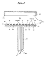
- FIG. 4 sets forth an exploded view of the mounting table.
- FIG. 5 depicts a cross sectional configuration view of a heat treatment apparatus in accordance with a second preferred embodiment of the present invention.
- FIG. 6 is a perspective view of a heating unit for use in the second preferred embodiment.
- FIG. 7 provides a partially enlarged cross sectional view of the heating unit shown in FIG. 6 .
- FIG. 8 illustrates an enlarged cross sectional view of a modified embodiment of the heating unit.
- FIG. 1 provides a cross sectional configuration view of a heat treatment apparatus in accordance with the first preferred embodiment of the present invention
- FIG. 2 shows a cross sectional view of an arrangement of quartz tubes provided in the mounting table
- FIG. 3 presents a cross sectional view of the mounting table
- FIG. 4 sets forth an exploded view of the mounting table.
- a heat treatment apparatus 2 has a processing chamber 4 whose inside is roughly cylindrical in shape and which is made of aluminum.
- a shower head unit 6 which is a gas supply means used to introduce necessary processing gases, for example, film forming gas.
- a gas injection surface 8 which is a bottom surface of the shower head unit 6 has a plurality of gas injection openings 10 A and 10 B. And, the processing gases are injected from the plurality of gas injection openings 10 A and 10 B to a processing space S.
- the processing gases are diffused in the horizontal direction in the gas diffusion areas 12 A and 12 B, and then injected from the gas injection openings 10 A and 10 B connected to the gas diffusion areas 12 A and 12 B, respectively. That is, the gas injection openings 10 A and 10 B are arranged in a matrix shape.
- the whole shower head unit 6 is made of, for example, nickel, nickel alloy such as Hastelloy (trademark) or the like, aluminum, or aluminum alloy.
- the shower head unit 6 may have only one gas diffusion area.
- a sealing member which is composed of, e.g., an O-ring or the like is placed. Accordingly, airtightness is maintained in the processing chamber 4 .
- a loading/unloading port 16 is installed to load and unload a semiconductor wafer W as a target object.
- a gate valve 18 capable of airtightly opening and closing the loading/unloading port 16 is installed.
- an exhaust space 22 is formed at a bottom portion 20 of the processing chamber 4 .
- a large opening 24 is formed at the center of the bottom portion 20 of the processing chamber 4 , and a cylindrical partition wall 26 of a cylindrical body which has a bottom portion is extended downward from the opening 24 , and the inside of the cylindrical partition wall 26 serves as the exhaust space 22 .
- an upright cylindrical support column 30 made of, e.g., quartz glass.
- a mounting table 32 is fixed by welding onto an upper portion of the cylindrical support column 30 .
- the cylindrical support column 30 can be made of ceramic such as AlN.
- the diameter of the opening 24 on the entrance side of the exhaust space 22 is set to be less than that of the mounting table 32 . Accordingly, a processing gas which flows downward through the outside of the peripheral portion of mounting table 32 , flows around to the bottom portion of the mounting table 32 , and then flows into the opening 24 .
- a gas exhaust port 34 connected to the exhaust space 22 .
- a vacuum pumping system 38 is connected to the gas exhaust port 34 .
- the vacuum pumping system 38 is formed of a gas exhaust line 36 equipped with a vacuum pump (not shown). Accordingly, the atmosphere inside the processing chamber 4 and the exhaust space 22 can be pumped to be evacuated to vacuum.
- a pressure control valve (not shown) capable of controlling the opening ratio is installed in the middle of the gas exhaust line 36 .
- the internal pressure of the processing chamber 4 can be maintained at a constant level by controlling the opening ratio of the pressure control valve automatically, or a pressure value can be adjusted quickly to a desired level.
- the mounting table 32 is provided with a heating unit 40 which is a feature of the present invention.
- a mounting table cover member 42 is installed to cover the heating unit 40 .
- a semiconductor wafer W can be mounted as a target object.
- the heating unit 40 is connected to feeder lines 44 disposed in the support column 30 . Accordingly, while being controlled, electric powers are supplied to the heating unit 40 .
- These feeder lines 44 are inserted in quartz tubes (not shown) in the drawings, and are connected to the power cables under the support column 30 . Further, as will be described later, the heating unit 40 is divided into, for example, an inner zone and an outer zone which encloses the exterior of the inner zone in a concentric circular shape to control an electric power of each zone separately.
- four feeder lines 44 are prepared in an example shown in the drawing.
- a plurality of, for example, three pin insertion through holes 46 is provided through the mounting table 32 in vertical direction ( FIG. 1 illustrates only two pin insertion through holes).
- a vertically movable upthrust pin 48 is inserted loosely through each pin insertion through hole 46 .
- a circular ring-shaped upthrust ring 50 made of ceramic such as alumina is arranged under the upthrust pins 48 . That is, the bottom of each vertically movable upthrust pin 48 is not fixedly supported by upthrust ring 50 .
- An arm unit 52 extended from the upthrust ring 50 is connected to up/down rod 54 which passes through a bottom portion 20 , and the up/down rod 54 is driven vertically by an actuator 56 .
- the upthrust pins 48 move up or down from the upper end of pin insertion through holes 46 when replacing the wafer W. Further, between the actuator 56 and a through portion, at the bottom portion 20 of the processing chamber 4 , through which the up/down rod 54 of the actuator 56 passes, an expansible bellows 58 is interposed. Accordingly, the up/down rod 54 can be vertically movable while maintaining the airtightness of the processing chamber 4 .
- the mounting table 32 and the heating unit 40 will now be described in detail with reference to FIGS. 2 to 4 .
- the upthrust pins 48 and the pin insertion through holes 46 are omitted in FIGS. 2 to 4 .
- the mounting table 32 is primarily composed of the heating unit 40 and the mounting table cover member 42 prepared to cover the whole top surface of the heating unit 40 .
- the heating unit 40 functions as a target object heating unit which applies heat to the wafer W.
- the heating unit 40 has a circular plate-shaped reflector plate 60 which has a greater diameter than that of the wafer W.
- the whole reflector plate 60 is made of strongly heat-resistant opaque quartz which is white turbid since it is intermixed with fine bubbles.
- the surface of the reflector plate 60 is non-transparent to externally incident heat rays, and reflects the heat rays with high reflectivity.
- the opaque quartz forming the reflector plate 60 can be intermixed with any materials other than bubbles and the surface thereof may be mirror finished as long as it is non-transparent to heat rays.
- an upright positioning projection 61 is prepared in the upper direction at the peripheral region of the reflector plate 60 .
- the positioning projection 61 performs the positioning of the mounting table cover member 42 which is inserted by the positioning projection 61 .
- the positioning projection 61 can be made into a ring-shape by using the same material as that of the reflector plate 60 . It can be installed integrally with the reflector plate 60 or separately from the reflector plate 60 .
- the positioning projection 61 contacts with the mounting table cover member 42 , and also functions to transfer heat efficiently from the reflector plate 60 to the mounting table cover member 42 (wafer W side). Accordingly, the falling of the temperature at the peripheral region of a wafer can be prevented and thus the temperature difference between the central portion and the peripheral portion of the wafer decreases.
- the top end of the support column 30 made of quartz is welded around the center portion of the bottom surface of the reflector plate 60 .
- strongly heat-resistant and transparent quartz tubes 62 which are formed to be bent in a predetermined shape are welded to the top surface of the reflector plate 60 .
- Carbon wires 64 which generate Joule heat when a current is applied thereto are inserted in these quartz tubes 62 .
- a heater of this kind formed by inserting the carbon wire 64 in the quartz tube 62 is described in, e.g., Japanese Patent Laid-open Application No. 2001-208478 describes.
- joint pins 66 also made of quartz, are used. Specifically, these joint pins 66 are disposed at proper places between the quartz tubes 62 and the reflector plate 60 , and by melting them, the quartz tubes 62 and the reflector plate 60 are welded together.
- the quartz tubes 62 are formed to be bent so that they include a quartz tube portion 62 A in an inner zone and a quartz tube portion 62 B in an outer zone which encompasses the exterior of the quartz tube portion 62 A.
- Each of the quartz tube portions 62 A and 62 B has two concentric circular portions and two end portions which are concentered at the central portion of the reflector plate 60 for supplying electric power. The both end portions pass through the reflector plate 60 downward.
- the carbon wire 64 in each of the quartz tube portions 62 A and 62 B is connected to the feeder lines 44 . Accordingly, application of electric power can be controlled separately in each zone. Further, the number of zones is not limited to 2. It may be 3 or more.
- Each of the quartz tube portions 62 A and 62 B can be easily bent in a desired shape by heat process. Further, the quartz tube portions 62 A and 62 B are easily jointed to the surface of the reflector plate 60 by using the joint pins 66 . Heat rays from the carbon wires 64 in the quartz tube portions 62 A and 62 B are reflected at the surface of the reflector plate 60 which has high heat-resistance, and directed upward in the example shown in the drawing.
- the mounting table cover member 42 is installed to cover the whole top surface of the heating unit 40 fabricated as described above. As a result, the whole mounting table 32 is constructed. Specifically, the mounting table cover member 42 is formed to have a circular lid shape and made of light absorbing material, e.g., SiC, which has a good thermal conductivity but with negligible metal impurities. An inner surface of a sidewall 42 A of the lid-shaped mounting table cover member 42 is set to have a slightly greater diameter than that of the reflector plate 60 , and it is in close contact with a side surface of the reflector plate 60 to be generally circumscribed thereto.
- light absorbing material e.g., SiC
- the mounting table cover member 42 when being attached to the reflector plate 60 from above, the mounting table cover member 42 is combined with the reflector plate 60 while being positioned at a specific place by the positioning projection 61 . And, the wafer W is mounted on the top surface of the mounting table cover member 42 . Further, the inner space of the mounting table cover member 42 may be sealed completely by airtightly thermal-bonding the peripheral regions of the mounting table cover member 42 and the reflector plate 60 together, and further, by thermal-bonding quartz pipes at portions of the pin insertion through holes 46 (see FIG. 1 ).
- a semiconductor wafer W not processed is held by a transfer arm (not shown) and loaded into the processing chamber 4 through the open gate valve 18 and the loading/unloading port 16 .
- This wafer W is loaded on the upthrust pins 48 which are in their elevated position. And then, the upthrust pins 48 move down, and the wafer W is mounted and supported on the top surface of the mounting table 32 , specifically on the top surface of the mounting table cover member 42 .
- flow-controlled processing gases e.g., film forming gases such as TiCl 4 , H 2 , NH 3 , WF 6 , SiH 4 , H 2 , PET, and O 2 .
- film forming gases such as TiCl 4 , H 2 , NH 3 , WF 6 , SiH 4 , H 2 , PET, and O 2 .
- These gases are emitted (injected) through the gas injection holes 10 A and 10 B into the processing space S.
- the vacuum pump not shown
- the atmosphere in the processing chamber 4 and the exhaust space 22 is exhausted to vacuum; and further, the opening ratio of the pressure control valve is controlled automatically, and thus the atmosphere in the processing space S is maintained at a predetermined process pressure level.
- the wafer W is heated by the heating unit 40 provided in the mounting table 32 and thus the temperature of the wafer is maintained at a predetermined process temperature level. Accordingly, thin films such as Ti, TiN, W, WSi, Ta 2 O 5 are formed on the surface of the semiconductor wafer W. Further, when using TMA (Tri-Methyl Aluminum) and ozone as film forming gases, an alumina (Al 2 O 3 ) film can be formed.
- TMA Tri-Methyl Aluminum
- ozone ozone
- heat rays from the carbon wires 64 inserted in quartz tubes 62 ( 62 A and 62 B) of the heating unit 40 radiate in all directions. Heat rays emitted downward, however, are reflected upward at the surface of the reflector plate 60 supporting and fixing quartz tubes 62 and made of opaque quartz, and thus apply heat to the mounting table cover member 42 , and further, the wafer W mounted on the top surface thereof.
- the reflector plate 60 which constitutes the heating unit 40 is made of high-purity opaque quartz which contains hardly any impurities.
- the quartz tubes 62 and the carbon wires 64 also contain hardly any impurities and thus have high purity. Accordingly, contamination such as organic contamination and/or metal contamination can be substantially suppressed.
- the relatively easy fabrication processes for the reflector plate 60 and the quartz tubes 62 substantially reduce the manufacturing cost. Further, thermal energy can be used effectively and efficiently by using the reflector plate 60 .
- the mounting table cover member 42 which is a part constituting the mounting table 32 , is made of a light absorbing material, e.g., SiC, having a good thermal conductivity and a high purity. Therefore, the mounting table cover member 42 can be heated while maintaining the in-surface temperature uniformity of the wafer W at a high level.
- the mounting table cover member 42 can be made of arbitrary light absorbing material, e.g., opaque quartz intermixed with carbon.
- the main components of the heating unit 40 are made of quartz, strongly resistant to thermal shocks. Accordingly, a high temperature rising rate, for example, about 1000° C./5 minutes can be obtained.
- FIG. 5 depicts a cross sectional configuration view of a heat treatment apparatus in accordance with the second preferred embodiment of the present invention
- FIG. 6 is a perspective view of a heating unit for use in the second preferred embodiment
- FIG. 7 provides a partially enlarged cross sectional view of the heating unit shown in FIG. 6 .
- the heat treatment apparatus 70 of the second preferred embodiment has a cylindrical processing chamber 4 ′ made of, for example, aluminum.
- a rectangular-shaped space is provided, for example.
- a ceiling portion 74 made of, for example, aluminum or the like is attached via a sealing member 72 which is formed of, e.g., O-ring or the like.
- a cylindrical mounting table receiving vessel 76 of a relatively large-diameter is formed in a downward protruding shape.
- a mounting table 78 made of ceramic, e.g., SiC or the like, is installed for mounting thereon a semiconductor wafer W as a target object.
- a resistance heater 80 which is a target object heating unit to apply heat to the wafer W is encapsulated.
- a rotation axis 83 extended downward is fixedly attached.
- the rotation axis 83 passes through a bottom plate 82 of the mounting table receiving vessel 76 via, e.g., a rotatable magnetic fluid sealing 84 . Accordingly, the rotation axis 83 is supported rotatably and airtightly. Further, the bottom plate 82 is airtightly jointed to the lower end of the mounting table receiving vessel 76 by an expansible and contractible bellows 86 . Accordingly, the bottom plate 82 and the mounting table 78 can be vertically movable as a unit by an actuator (not shown). Further, lifter pins (not shown) are provided on the bottom plate 82 for lifting the wafer W.
- a gate valve 88 opened and closed when the wafer W is loaded and unloaded is installed on a lower sidewall of the mounting table receiving vessel 76 .
- the loading and the transport of the wafer W are performed via the gate valve 88 between the inside and the outside.
- first and a second gas supply units 90 and 92 are installed on two opposite sides with the mounting table 78 being at the center therebetween. From the first and the second gas supply units 90 and 92 , flow-controlled processing gases, e.g., film forming gases, are supplied when necessary.
- the first and the second gas supply units 90 and 92 are formed of, e.g., heat-resistant quartz pipes and have nozzles 90 A and 92 A.
- the respective nozzles 90 A and 92 A can be arranged on two opposite sides in the processing chamber 4 ′ in such a manner that a plurality of nozzles is arranged in parallel on each side. In this case, the processing gases can be supplied in a planar shape.
- a first and a second, vacuum pumping systems 94 and 96 are installed in a manner of corresponding to the first and the second gas supply units 90 and 92 .
- the atmosphere in the processing chamber 4 ′ can be pumped to be evacuated to vacuum by vacuum pumps (not shown) of the vacuum pumping systems 94 and 96 when necessary.
- the first and the second vacuum pumping systems 94 and 96 are respectively connected to the gas exhaust ports 94 A and 96 A fronting the processing space.
- a lid-shaped inner vessel 98 is installed in such a manner of covering processing space S on the mounting table 78 .
- the inner vessel 98 has a good heat resistance, and further, it is made of a high-purity light absorbing material, e.g., SiC, which contains hardly any impurities of metal atoms or the like.
- the inner vessel 98 has the functions to be heated and thus accelerate the process reactions, and to align the gas flow of the processing gases.
- a heating unit 100 which is the feature of the present invention is installed between the inner vessel 98 and a wall surface of the ceiling plate 74 of the processing chamber 4 ′.
- the basic configuration of the heating unit 100 is substantially the same as that of the heating unit 40 described in conjunction with FIGS. 2 to 4 .
- the heating unit 100 has a substantially rectangular-shaped reflector plate 102 which is greater than a diameter of the wafer W.
- the whole reflector plate 102 is made of strongly heat-resistant opaque quartz which is white turbid since it is intermixed with fine bubbles.
- the surface of the reflector plate 102 is non-transparent to externally incident heat rays, and reflects such heat rays with high reflectivity.
- the top surface of the reflector plate 102 is attached on the bottom surface of the ceiling plate 74 .
- a strongly heat-resistant and transparent quartz tube 104 formed to be bent in a predetermined shape, is jointed by welding to the bottom surface of the reflector plate 102 .
- a carbon wire 106 which generates Joule heat when a current is applied thereto is inserted in the quartz tube 104 .
- Connecting terminals 110 at two ends of carbon wire 106 upwardly pass through the reflector plate 102 , and also pass through the ceiling plate 74 airtightly to be extended to the outside.
- joint pins 108 (see FIGS. 6 and 7 ), also made of quartz, are used. Specifically, these joint pins 108 are disposed at proper places between the quartz tube 104 and the reflector plate 102 , and by melting them, the quartz tube 104 and the reflector plate 102 are welded together.
- heat rays from the carbon wire 106 inside the quartz tube 104 are reflected at the surface of the reflector plate 102 having high heat-resistance, and directed altogether downward in FIG. 5 . Accordingly, the inner vessel 98 made of a light absorbing material can be heated to a predetermined temperature level. Further, a cooling jacket 112 is installed in the ceiling plate 74 to cool the ceiling plate 74 . By flowing a coolant such as cooling water or the like in the cooling jacket 112 , the ceiling plate 74 can be cooled.
- the wafer W mounted on the mounting table 78 is heated and maintained at a predetermined temperature level, primarily by the resistance heater 80 embedded in the mounting table 78 .
- the inner vessel 98 prepared in the processing chamber 4 ′ is heated uniformly by the heating unit 100 prepared on an upper side of the inner vessel 98 . That is, the heat rays from the carbon wire 106 inserted in the quartz tube 104 of the heating unit 100 are absorbed in the inner vessel 98 made of a light absorbing material, directly, or indirectly by being reflected by the reflector plate 102 supporting quartz tube 104 , and thus heat the inner vessel 98 to a predetermined temperature level.
- the inner processing chamber 98 is supplied with film forming gases, as processing gases, in an intermittent manner, so that thin films are laminated into a multilayer stack.
- a flow-controlled TMA (Tri-Methyl Aluminum) gas is supplied intermittently from the first gas supply unit 90
- a flow-controlled ozone gas is supplied intermittently from the second gas supply unit 92 , flowing alternately with the supply of TMA gas. Accordingly, thin alumina films are laminated into a multilayer stack on the surface of the wafer W.
- the second vacuum pumping system 96 on the opposite side of the nozzle 90 A is driven, hence a gas flow in the direction of the arrow A 1 is formed in the processing space S.
- the first vacuum pumping system 94 on the opposite side of the nozzle 92 A is driven, so that a gas flow in the direction of the arrow A 2 , opposite from A 1 , is formed in the processing space S.
- the reflector plate 102 which constitutes the heating unit 100 is made of high-purity opaque quartz which contains hardly any impurities.
- the quartz tube 104 and the carbon wire 106 also have a high purity containing hardly any impurities. Thus, contamination such as organic contamination and/or metal contamination can be substantially suppressed.
- the relatively easy fabrication processes for the reflector plate 102 and the quartz tube 104 substantially reduce the manufacturing cost. Further, thermal energy can be used effectively and efficiently by using the reflector plate 102 .
- the main components of the heating unit 100 are made of quartz which is strongly resistant to thermal shocks. Accordingly, a high temperature rising rate, for example, about 1000° C./5 minutes can be obtained.
- the mounting table 78 of the second preferred embodiment instead of the mounting table 78 of the second preferred embodiment, the mounting table 32 described with reference to FIGS. 1 to 4 , that is, the mounting table which includes the integrally built-in heating unit can be used. In this case, contamination to the wafer W can be suppressed still further.
- heating lamps can be used instead of the resistance heater 80 as a target object heating unit.
- the inner vessel 98 may be made of transparent or opaque quartz. Further, a target object can be heated directly without installing the inner vessel 98 .
- the present invention is not limited thereto.
- the present invention can be applied to any film forming processes.
- the heating unit 40 ( 100 ) is formed by inserting the carbon wire 64 ( 106 ) in the transparent quartz tube 62 ( 104 ) in the above-described preferred embodiments
- the present invention is not limited thereto.
- the lower half portion (upper half portion) of the quartz tube 62 ( 104 ) may be made of opaque quartz for reflection, and the upper half portion (lower half portion) may be made of transparent quartz to raise the thermal efficiency.
- a wafer has to be positioned on the side of transparent quartz.
- the present invention is not limited thereto.
- the present invention can be applied to different heat treatment processes such as oxidation/diffusion process, annealing process, and quality modification process.
- the present invention is not limited thereto.
- the present invention can be applied to such apparatus as plasma CVD processing apparatus, etching processing apparatus, oxidation/diffusion processing apparatus, and sputter processing apparatus.
- the present invention is not limited thereto.
- the present invention can be applied to LCD substrate, glass substrate and the like.
Landscapes
- Engineering & Computer Science (AREA)
- Mechanical Engineering (AREA)
- General Engineering & Computer Science (AREA)
- Chemical Vapour Deposition (AREA)
- Surface Heating Bodies (AREA)
Abstract
Description
Claims (12)
Applications Claiming Priority (3)
| Application Number | Priority Date | Filing Date | Title |
|---|---|---|---|
| JP2003-178690 | 2003-06-23 | ||
| JP2003178690A JP4380236B2 (en) | 2003-06-23 | 2003-06-23 | Mounting table and heat treatment device |
| PCT/JP2004/008747 WO2004114377A1 (en) | 2003-06-23 | 2004-06-22 | Heat treatment apparatus |
Publications (2)
| Publication Number | Publication Date |
|---|---|
| US20070095289A1 US20070095289A1 (en) | 2007-05-03 |
| US7658801B2 true US7658801B2 (en) | 2010-02-09 |
Family
ID=33534995
Family Applications (1)
| Application Number | Title | Priority Date | Filing Date |
|---|---|---|---|
| US10/561,017 Expired - Fee Related US7658801B2 (en) | 2003-06-23 | 2004-06-22 | Heat treatment apparatus |
Country Status (3)
| Country | Link |
|---|---|
| US (1) | US7658801B2 (en) |
| JP (1) | JP4380236B2 (en) |
| WO (1) | WO2004114377A1 (en) |
Cited By (3)
| Publication number | Priority date | Publication date | Assignee | Title |
|---|---|---|---|---|
| US20100043709A1 (en) * | 2006-11-02 | 2010-02-25 | Pyung-Yong Um | Chemical vapor deposition apparatus for equalizing heating temperature |
| US20180255612A1 (en) * | 2017-03-02 | 2018-09-06 | Coorstek Kk | Planar heater |
| US20220322492A1 (en) * | 2021-04-06 | 2022-10-06 | Applied Materials, Inc. | Epitaxial deposition chamber |
Families Citing this family (26)
| Publication number | Priority date | Publication date | Assignee | Title |
|---|---|---|---|---|
| EP1672715A1 (en) * | 2004-12-17 | 2006-06-21 | Applied Films GmbH & Co. KG | Apparatus for coating a substrate |
| JP5066336B2 (en) * | 2005-12-14 | 2012-11-07 | 東京エレクトロン株式会社 | High pressure processing apparatus and high pressure processing method |
| JP5245268B2 (en) | 2006-06-16 | 2013-07-24 | 東京エレクトロン株式会社 | Mounting table structure and heat treatment apparatus |
| JP2008066413A (en) * | 2006-09-05 | 2008-03-21 | Tokyo Electron Ltd | Shower head structure and processing apparatus using the same |
| JP2008297615A (en) * | 2007-06-01 | 2008-12-11 | Tokyo Electron Ltd | Substrate mounting mechanism and substrate processing apparatus provided with the substrate mounting mechanism |
| JP5195227B2 (en) * | 2008-09-25 | 2013-05-08 | 東京エレクトロン株式会社 | Film forming apparatus and method of using the same |
| JP5056735B2 (en) * | 2008-12-02 | 2012-10-24 | 東京エレクトロン株式会社 | Deposition equipment |
| JP5500914B2 (en) * | 2009-08-27 | 2014-05-21 | 株式会社半導体エネルギー研究所 | Laser irradiation device |
| JP2011176028A (en) * | 2010-02-23 | 2011-09-08 | Utec:Kk | Pressurizing-type lamp annealing device, method for manufacturing thin film, and method for using pressurizing-type lamp annealing device |
| DE102010028958B4 (en) * | 2010-05-12 | 2014-04-30 | Von Ardenne Anlagentechnik Gmbh | Substrate treatment plant |
| JP5129848B2 (en) * | 2010-10-18 | 2013-01-30 | 東京エレクトロン株式会社 | Joining apparatus and joining method |
| KR101528138B1 (en) * | 2011-01-18 | 2015-06-12 | 가부시키가이샤 히다치 고쿠사이 덴키 | Substrate processing apparatus, substrate supporting tool and method of manufacturing semiconductor device |
| DE102011081749B4 (en) | 2011-04-29 | 2016-04-14 | Von Ardenne Gmbh | Substrate treatment plant |
| KR102106969B1 (en) * | 2013-02-26 | 2020-05-08 | 삼성디스플레이 주식회사 | Apparatus and methods for heat-treating substrate |
| CN203807555U (en) * | 2014-03-31 | 2014-09-03 | 上海理想万里晖薄膜设备有限公司 | High temperature heating device preventing corrosion of fluorine |
| JP6447393B2 (en) * | 2015-07-06 | 2019-01-09 | 東京エレクトロン株式会社 | Film forming apparatus, film forming method, and storage medium |
| JP6318139B2 (en) * | 2015-12-25 | 2018-04-25 | 株式会社日立国際電気 | Substrate processing apparatus, semiconductor device manufacturing method, and program |
| JP6789040B2 (en) * | 2016-08-30 | 2020-11-25 | 東京応化工業株式会社 | Substrate heating device and substrate heating method |
| JP6757629B2 (en) * | 2016-08-30 | 2020-09-23 | 東京応化工業株式会社 | Substrate heating device, substrate heating method and infrared heater |
| JP1581406S (en) * | 2016-10-14 | 2017-07-18 | ||
| CN107841727A (en) * | 2017-12-15 | 2018-03-27 | 北京创昱科技有限公司 | A kind of cooling component and vacuum coating equipment |
| JP6718950B2 (en) * | 2018-12-26 | 2020-07-08 | 東京応化工業株式会社 | Substrate heating device and method for manufacturing polyimide film |
| JP7584537B2 (en) * | 2020-08-03 | 2024-11-15 | アプライド マテリアルズ インコーポレイテッド | Wafer edge temperature compensation in batch thermal processing chambers |
| JP1684469S (en) * | 2020-09-24 | 2021-05-10 | Ceiling heater for substrate processing equipment | |
| JP7619734B2 (en) * | 2021-03-15 | 2025-01-22 | 東京エレクトロン株式会社 | Substrate Processing Equipment |
| WO2024257286A1 (en) * | 2023-06-14 | 2024-12-19 | 住友電気工業株式会社 | Wafer-holding table and semiconductor processing device |
Citations (12)
| Publication number | Priority date | Publication date | Assignee | Title |
|---|---|---|---|---|
| JPS63278322A (en) * | 1987-05-11 | 1988-11-16 | Fujitsu Ltd | Vapor growth device |
| JPH0722500A (en) | 1993-06-29 | 1995-01-24 | Tokyo Electron Ltd | Processor |
| US5612132A (en) * | 1992-11-23 | 1997-03-18 | Cvd, Incorporated | Chemical vapor deposition-produced silicon carbide having improved properties |
| US5904872A (en) * | 1994-09-29 | 1999-05-18 | Tokyo Electron Limited | Heating device, method of manufacturing the same, and processing apparatus using the same |
| JP2000021890A (en) | 1997-07-31 | 2000-01-21 | Toshiba Ceramics Co Ltd | Carbon heater |
| US6043468A (en) | 1997-07-21 | 2000-03-28 | Toshiba Ceramics Co., Ltd. | Carbon heater |
| US6254687B1 (en) * | 1999-03-26 | 2001-07-03 | Japan Process Engineering, Ltd. | Chemical vapor deposition system with reduced material deposition on chamber wall surfaces |
| JP2001208478A (en) | 2000-01-31 | 2001-08-03 | Tokyo Electron Ltd | Heat treatment equipment |
| US6369361B2 (en) * | 2000-01-28 | 2002-04-09 | Tokyo Electron Limited | Thermal processing apparatus |
| US6407371B1 (en) * | 1998-12-01 | 2002-06-18 | Toshiba Ceramics Co., Ltd. | Heater |
| US6448536B2 (en) * | 2000-04-07 | 2002-09-10 | Tokyo Electron Limited | Single-substrate-heat-processing apparatus for semiconductor process |
| US20030094446A1 (en) * | 2001-04-17 | 2003-05-22 | Mattson Technology, Inc. | Rapid thermal processing system for integrated circuits |
-
2003
- 2003-06-23 JP JP2003178690A patent/JP4380236B2/en not_active Expired - Fee Related
-
2004
- 2004-06-22 US US10/561,017 patent/US7658801B2/en not_active Expired - Fee Related
- 2004-06-22 WO PCT/JP2004/008747 patent/WO2004114377A1/en not_active Ceased
Patent Citations (12)
| Publication number | Priority date | Publication date | Assignee | Title |
|---|---|---|---|---|
| JPS63278322A (en) * | 1987-05-11 | 1988-11-16 | Fujitsu Ltd | Vapor growth device |
| US5612132A (en) * | 1992-11-23 | 1997-03-18 | Cvd, Incorporated | Chemical vapor deposition-produced silicon carbide having improved properties |
| JPH0722500A (en) | 1993-06-29 | 1995-01-24 | Tokyo Electron Ltd | Processor |
| US5904872A (en) * | 1994-09-29 | 1999-05-18 | Tokyo Electron Limited | Heating device, method of manufacturing the same, and processing apparatus using the same |
| US6043468A (en) | 1997-07-21 | 2000-03-28 | Toshiba Ceramics Co., Ltd. | Carbon heater |
| JP2000021890A (en) | 1997-07-31 | 2000-01-21 | Toshiba Ceramics Co Ltd | Carbon heater |
| US6407371B1 (en) * | 1998-12-01 | 2002-06-18 | Toshiba Ceramics Co., Ltd. | Heater |
| US6254687B1 (en) * | 1999-03-26 | 2001-07-03 | Japan Process Engineering, Ltd. | Chemical vapor deposition system with reduced material deposition on chamber wall surfaces |
| US6369361B2 (en) * | 2000-01-28 | 2002-04-09 | Tokyo Electron Limited | Thermal processing apparatus |
| JP2001208478A (en) | 2000-01-31 | 2001-08-03 | Tokyo Electron Ltd | Heat treatment equipment |
| US6448536B2 (en) * | 2000-04-07 | 2002-09-10 | Tokyo Electron Limited | Single-substrate-heat-processing apparatus for semiconductor process |
| US20030094446A1 (en) * | 2001-04-17 | 2003-05-22 | Mattson Technology, Inc. | Rapid thermal processing system for integrated circuits |
Cited By (6)
| Publication number | Priority date | Publication date | Assignee | Title |
|---|---|---|---|---|
| US20100043709A1 (en) * | 2006-11-02 | 2010-02-25 | Pyung-Yong Um | Chemical vapor deposition apparatus for equalizing heating temperature |
| US8876976B2 (en) * | 2006-11-02 | 2014-11-04 | Eugene Technology Co., Ltd. | Chemical vapor deposition apparatus for equalizing heating temperature |
| US20180255612A1 (en) * | 2017-03-02 | 2018-09-06 | Coorstek Kk | Planar heater |
| US10674566B2 (en) * | 2017-03-02 | 2020-06-02 | Coorstek Kk | Planar heater |
| US20220322492A1 (en) * | 2021-04-06 | 2022-10-06 | Applied Materials, Inc. | Epitaxial deposition chamber |
| US12324061B2 (en) * | 2021-04-06 | 2025-06-03 | Applied Materials, Inc. | Epitaxial deposition chamber |
Also Published As
| Publication number | Publication date |
|---|---|
| JP2005019479A (en) | 2005-01-20 |
| US20070095289A1 (en) | 2007-05-03 |
| WO2004114377A1 (en) | 2004-12-29 |
| JP4380236B2 (en) | 2009-12-09 |
Similar Documents
| Publication | Publication Date | Title |
|---|---|---|
| US7658801B2 (en) | Heat treatment apparatus | |
| US6537422B2 (en) | Single-substrate-heat-processing apparatus for semiconductor process | |
| US6402848B1 (en) | Single-substrate-treating apparatus for semiconductor processing system | |
| US8183502B2 (en) | Mounting table structure and heat treatment apparatus | |
| KR101312676B1 (en) | Active cooling substrate support | |
| US6506253B2 (en) | Photo-excited gas processing apparatus for semiconductor process | |
| US6228173B1 (en) | Single-substrate-heat-treating apparatus for semiconductor process system | |
| CN100494821C (en) | Heating medium circulating device and thermal treatment equipment usint the device | |
| US5462603A (en) | Semiconductor processing apparatus | |
| JP3480271B2 (en) | Shower head structure of heat treatment equipment | |
| CN100495655C (en) | Gas treatment device and heat readiting method | |
| US7019263B2 (en) | Substrate heating apparatus and multi-chamber substrate processing system | |
| US10727093B2 (en) | Light pipe window structure for low pressure thermal processes | |
| US20090165720A1 (en) | Substrate treating apparatus | |
| KR101528138B1 (en) | Substrate processing apparatus, substrate supporting tool and method of manufacturing semiconductor device | |
| WO2004090960A1 (en) | Loading table and heat treating apparatus having the loading table | |
| US20070095284A1 (en) | Gas treating device and film forming device | |
| JPH08111449A (en) | Processing equipment | |
| JP2004356624A (en) | Mounting table structure and heat treatment equipment | |
| WO2011099481A1 (en) | Mounting table structure, and processing device | |
| KR20040010620A (en) | Processing apparatus and processing method | |
| US9082797B2 (en) | Substrate processing apparatus and method of manufacturing semiconductor device | |
| JP5465828B2 (en) | Substrate processing apparatus and semiconductor device manufacturing method | |
| JP2007141895A (en) | Mounting table structure and film forming apparatus | |
| KR102495469B1 (en) | batch processing chamber |
Legal Events
| Date | Code | Title | Description |
|---|---|---|---|
| AS | Assignment |
Owner name: TOKYO ELECTRON LIMITED,JAPAN Free format text: ASSIGNMENT OF ASSIGNORS INTEREST;ASSIGNOR:ARAMI, JUNICHI;REEL/FRAME:019438/0256 Effective date: 20051128 Owner name: TOKYO ELECTRON LIMITED, JAPAN Free format text: ASSIGNMENT OF ASSIGNORS INTEREST;ASSIGNOR:ARAMI, JUNICHI;REEL/FRAME:019438/0256 Effective date: 20051128 |
|
| FEPP | Fee payment procedure |
Free format text: PAYOR NUMBER ASSIGNED (ORIGINAL EVENT CODE: ASPN); ENTITY STATUS OF PATENT OWNER: LARGE ENTITY |
|
| FPAY | Fee payment |
Year of fee payment: 4 |
|
| FEPP | Fee payment procedure |
Free format text: MAINTENANCE FEE REMINDER MAILED (ORIGINAL EVENT CODE: REM.) |
|
| LAPS | Lapse for failure to pay maintenance fees |
Free format text: PATENT EXPIRED FOR FAILURE TO PAY MAINTENANCE FEES (ORIGINAL EVENT CODE: EXP.) |
|
| STCH | Information on status: patent discontinuation |
Free format text: PATENT EXPIRED DUE TO NONPAYMENT OF MAINTENANCE FEES UNDER 37 CFR 1.362 |
|
| FP | Lapsed due to failure to pay maintenance fee |
Effective date: 20180209 |