US765656A - Loose-leaf ledger. - Google Patents
Loose-leaf ledger. Download PDFInfo
- Publication number
- US765656A US765656A US13244602A US1902132446A US765656A US 765656 A US765656 A US 765656A US 13244602 A US13244602 A US 13244602A US 1902132446 A US1902132446 A US 1902132446A US 765656 A US765656 A US 765656A
- Authority
- US
- United States
- Prior art keywords
- covers
- springs
- leaves
- spring
- loose
- Prior art date
- Legal status (The legal status is an assumption and is not a legal conclusion. Google has not performed a legal analysis and makes no representation as to the accuracy of the status listed.)
- Expired - Lifetime
Links
- 238000003780 insertion Methods 0.000 description 4
- 230000037431 insertion Effects 0.000 description 4
- 239000000463 material Substances 0.000 description 4
- XKJMBINCVNINCA-UHFFFAOYSA-N Alfalone Chemical compound CON(C)C(=O)NC1=CC=C(Cl)C(Cl)=C1 XKJMBINCVNINCA-UHFFFAOYSA-N 0.000 description 1
- 229910000831 Steel Inorganic materials 0.000 description 1
- 230000006378 damage Effects 0.000 description 1
- 238000000034 method Methods 0.000 description 1
- 239000010959 steel Substances 0.000 description 1
Images

Classifications
-
- B—PERFORMING OPERATIONS; TRANSPORTING
- B42—BOOKBINDING; ALBUMS; FILES; SPECIAL PRINTED MATTER
- B42F—SHEETS TEMPORARILY ATTACHED TOGETHER; FILING APPLIANCES; FILE CARDS; INDEXING
- B42F13/00—Filing appliances with means for engaging perforations or slots
- B42F13/16—Filing appliances with means for engaging perforations or slots with claws or rings
- B42F13/20—Filing appliances with means for engaging perforations or slots with claws or rings pivotable about an axis or axes parallel to binding edges
- B42F13/28—Filing appliances with means for engaging perforations or slots with claws or rings pivotable about an axis or axes parallel to binding edges in two staggered sections
Definitions
- My object is to obtain a simple device that shall be easy to operate, positive in the performance of its functions, has no objectionable appearance, and no unsightly projections whatever to interfere with the ordinary handling and storing of the books.
- a further object is toprovide a book which having a given number of leaves need not necessarily be larger than an ordinary book having the same number of leaves and which may be as easily opened and closed.
- the leaves of the book may all or partially be removed without detriment to the covers, and thus the same covers may be used over and over again with new leaves in whole or in part without trouble or difficulty.
- Fig. 3 is a front elevation of the 'ished in any preferred manner.
- FIG. 4 isasection on lineX X of Fig. 3.
- Fig. 5 represents the key, and
- Fig. 6 shows a fragmentary section of a page.
- each connecting-spring 1 and 2 respectively designate the front andback covers of the book, the said covers being made of any suitable material and fin- Both covers are provided at their rear edges with wire rods 7 and 8, securely fastened to the material comprising the covers and running in the direction of the length of the book pass through loops formed by the outwardly-turned encircling ends of each connecting-spring in use.
- These springs 3 are preferably made of steel of uniform section formed into such shape as may be conveniently represented by the letter C and which in anormal unrestrained state form approximately a cylinder, the ends nearly touching each other. Midway in the width of these springs at the loop formed at each of their ends and immediately adjacent thereto a portion of the.
- the wire rod 8 in passing entirely through one end of the spring 3 also passes through the end of one member of the distending device positioned in the opening at the spring end, the said distending device consisting of a slender round bar 4:, the same being adapted to enter andmove freely within a corresponding hollow cylindrical member 5 or sleeve attached to the opposite end of the spring 3.
- This member5 is by a shoulder formed near its upper end and abutting against the inner part of the spring, a portion of the member extending out through the opening in the spring end and a washer or flange 5 either integral therewith or separate, as may be preferred, to rest upon the'outer part surrounding the opening of the spring at its end.
- This hollow member or sleeve 5 is not held rigidly, but left free to adjust itself to the position it is obliged to assume by reason of its engagement with the other member 4.
- a device of the class described comprised of two covers, pivotally united to, and connected by, one or more appropriately-curved flat springs; of said springs and of distensible members permanently attached individually thereto; and of separable, extraneous means for operating said distensible members, all
- the combination of covers hinged at their rear edge to a plurality of springs; ofsprings, whose normal, unrestrained shape approximates a cylinder, having the ends turned outwardly, acentral rectangular portion removed from the ends, the remaining portions forming looped forks of equal size; of pins, extending from the cut-away portions of the springs, outwardly into the material of the covers and firmly embedded therein; of a post secured between one pair of the forks on the end of each looped spring; of a post-surrounding, tubular sleeve, attached to the opposite end of each spring; and of a key, having a threaded shank adapted to engage with the threads in the tubular sleeve, all substantially as shown and described.
- a book comprising in its entirety, the combination of covers, hinged together, through the medium of flat springs curved appropriately; of distending devices consisting of male and female members, attached at their extremities, to the springs, at their point of juncture with the covers; a plurality of leaves, provided with suitable apertures to enable them to be placed in position; all substantially as shown and described.
Landscapes
- Springs (AREA)
Description
PATENTED JULY 26, 1904 A. E. ANDERSON.
LOOSE. LEAF LEDGER.
APPLICATION FILED NOV. 22, 1902. v
2 SHEETS-SHEET 1.
H0 MODEL.
ATTORNEY.
No. 765,656. PATENTED JULY 26, 1904.
- A. E. ANDERSON.
LOOSE LEAF LEDGER.
APPLICATION FILED NOV. 22, 1902. no MODEL. 2 SHEET8-BHBBT 2.
7 WITNESSES: I INVEN TUB a Q wwwnfifl/llfd -A TTOHNE Y Patented July 26, 1904.
PATENT OFFICE.
AMBROSE E. ANDERSON, OF PITTSBURG, PENNSYLVANIA.
LOOSE-LEAF LEDGER.
SPECIFICATION forming part of Letters Patent N0. 765,656, dated July 26, 1904.
Application filed November 22, 1902. Serial No- 13Z,446. (No model.)
To all whom, it may concern.-
Be it known that I, AMBRosE E.ANDERsoN, a citizen of the United States, and a resident of Pittsburg, in the county of Allegheny and My invention relates to improvements in securing the pages or leaves of books within their covers in general, and more particularly. to that class of books used for keeping ac-.
counts and in which at times it is desirable to remove, insert, or exchange pages without destruction or mutilation thereof and which are commonly known as loose-leaf ledgers.
My object is to obtain a simple device that shall be easy to operate, positive in the performance of its functions, has no objectionable appearance, and no unsightly projections whatever to interfere with the ordinary handling and storing of the books.
A further object is toprovide a book which having a given number of leaves need not necessarily be larger than an ordinary book having the same number of leaves and which may be as easily opened and closed.
I attain these objects by the combination of specially-prepared sheets or pages which, together with the covers, are constrained and connected by appropriately-shaped distensible flat springs attached to and forming a part of the binding.
The leaves of the book may all or partially be removed without detriment to the covers, and thus the same covers may be used over and over again with new leaves in whole or in part without trouble or difficulty.
My invention will be readily understood from the detailed description herewith presented, reference being had to the accompanying drawings, forming a part of this speci-.
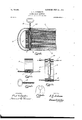
section of the book through the center of a spring.
Fig. 3 is a front elevation of the 'ished in any preferred manner.
spring and its attached parts. Fig. 4 isasection on lineX X of Fig. 3. Fig. 5 represents the key, and Fig. 6 shows a fragmentary section of a page.
Like numerals of reference designate corresponding parts in all the figures of the drawings. 7
1 and 2 respectively designate the front andback covers of the book, the said covers being made of any suitable material and fin- Both covers are provided at their rear edges with wire rods 7 and 8, securely fastened to the material comprising the covers and running in the direction of the length of the book pass through loops formed by the outwardly-turned encircling ends of each connecting-spring in use. These springs 3 are preferably made of steel of uniform section formed into such shape as may be conveniently represented by the letter C and which in anormal unrestrained state form approximately a cylinder, the ends nearly touching each other. Midway in the width of these springs at the loop formed at each of their ends and immediately adjacent thereto a portion of the. spring material is removed, leaving an opening rectangular in shape and of depth and width suflicient to al-' low the ends of the distending devices to be inserted, so-that the central plane of the sleeves andbars shall be coincident with the centers of the loops at the spring ends, as shown at 3 in Fig. 4 and as will be further explained, the whole being completely covered by the rear portion of the binding ordinarily connecting the covers of the book and which is attached thereto in the usual manner.
The wire rod 8 in passing entirely through one end of the spring 3 also passes through the end of one member of the distending device positioned in the opening at the spring end, the said distending device consisting of a slender round bar 4:, the same being adapted to enter andmove freely within a corresponding hollow cylindrical member 5 or sleeve attached to the opposite end of the spring 3. The method of securing this member5 to the spring end, so as to withstand the force exerted by it, is by a shoulder formed near its upper end and abutting against the inner part of the spring, a portion of the member extending out through the opening in the spring end and a washer or flange 5 either integral therewith or separate, as may be preferred, to rest upon the'outer part surrounding the opening of the spring at its end. This hollow member or sleeve 5 is not held rigidly, but left free to adjust itself to the position it is obliged to assume by reason of its engagement with the other member 4. It is prevented from turning and also held in position by short wire rods 7, which are screw-threaded into the head of the sleeve 5, on opposite sides thereof, as far in as possible without conflicting with the free passage of the screw-threaded key 6, which is fitted to coincide with the internal screw-threads shown atthe upper end of the sleeve. Both members 4: and 5 are covered by the binding of the book and do not appear on its surface except at a point immediately over the opening in the sleeve where the cover is perforated for the insertion of the key 6.
From the above it will be evident thatwith the leaves withdrawn the covers will be constrained to come into as close contact with each other as the length of the sleeves will permit and thatupon insertion of the threaded keys into the sleeves and turning the same therein the oppositely-disposed ends of the springs, together with the attached covers, will be forced apart in amount according to the number of. turns made, thus permitting the ready insertion of leaves at will. Upon turning the keys in the reverse direction the leaves will be compressed tightly together and securely held by the tension of the springs acting through the covers at the joint thereof. It is also evident that the joint between the covers of the book and the springs constitute, in effect, a hinge, readily permitting the covers to be opened and the leaves to be turned at will without freeing the leaves from the pressure of the springs or allowing them to get out of position in any way, and it may be further seen that the sleeves pass through the perforations in the leaves for this purpose,
while the slit (see Fig. 6) is to admit of withdrawal or insertion upon removal of the pressure.
I am aware that springs have hitherto been used for the purpose of holdingleaves. within covers, and hence do not broadly claim that principle as my own.
What I do claim, and desire to cover by Letters Patent, is
1. A device of the class described, comprised of two covers, pivotally united to, and connected by, one or more appropriately-curved flat springs; of said springs and of distensible members permanently attached individually thereto; and of separable, extraneous means for operating said distensible members, all
substantially as shown and described.
2. The combination of covers, pivotally united to the oppositely-disposed ends of a plurality of bent flat springs, means whereby the ends of said springs may be distended at will, leaves provided with slits and perforations to pass over said means of distension and adapted to be alined by them.
3. The combination of suitable springs, of U-shaped section, attached pivotally, at their extremities, to the covers of a book adapted to receive them; rods, or bars, attached loosely at one end to an end of the springs, at their pivotal point, extending in direction toward the other end of the springs; sleeves threaded internally, attached to the opposite ends of said springs, extending downwardly and loosely surrounding the said rods or bars; keys, threaded externally on their shanks to engage with the threads in the sleeves; pages, having bifurcated and perforated openings, adjacent to their rear edges, adapted to pass over and be constrained by the said rods and sleeves, all substantially as shown anddescribed.
4. In a device of the class described, the combination of covers, hinged at their rear edge to a plurality of springs; ofsprings, whose normal, unrestrained shape approximates a cylinder, having the ends turned outwardly, acentral rectangular portion removed from the ends, the remaining portions forming looped forks of equal size; of pins, extending from the cut-away portions of the springs, outwardly into the material of the covers and firmly embedded therein; of a post secured between one pair of the forks on the end of each looped spring; of a post-surrounding, tubular sleeve, attached to the opposite end of each spring; and of a key, having a threaded shank adapted to engage with the threads in the tubular sleeve, all substantially as shown and described.
5. A book, comprising in its entirety, the combination of covers, hinged together, through the medium of flat springs curved appropriately; of distending devices consisting of male and female members, attached at their extremities, to the springs, at their point of juncture with the covers; a plurality of leaves, provided with suitable apertures to enable them to be placed in position; all substantially as shown and described.
In testimony whereof I have affixed my signature in presence of two witnesses.
I AMBROSE E. ANDERSON. Witnesses:
HOWARD Q. TURNER, Jos. B. IMMLER.
Priority Applications (1)
| Application Number | Priority Date | Filing Date | Title |
|---|---|---|---|
| US13244602A US765656A (en) | 1902-11-22 | 1902-11-22 | Loose-leaf ledger. |
Applications Claiming Priority (1)
| Application Number | Priority Date | Filing Date | Title |
|---|---|---|---|
| US13244602A US765656A (en) | 1902-11-22 | 1902-11-22 | Loose-leaf ledger. |
Publications (1)
| Publication Number | Publication Date |
|---|---|
| US765656A true US765656A (en) | 1904-07-26 |
Family
ID=2834142
Family Applications (1)
| Application Number | Title | Priority Date | Filing Date |
|---|---|---|---|
| US13244602A Expired - Lifetime US765656A (en) | 1902-11-22 | 1902-11-22 | Loose-leaf ledger. |
Country Status (1)
| Country | Link |
|---|---|
| US (1) | US765656A (en) |
-
1902
- 1902-11-22 US US13244602A patent/US765656A/en not_active Expired - Lifetime
Similar Documents
| Publication | Publication Date | Title |
|---|---|---|
| US1462925A (en) | Spring binder post | |
| US765656A (en) | Loose-leaf ledger. | |
| US790779A (en) | Loose-leaf binder. | |
| US1700846A (en) | Bookmark | |
| US662518A (en) | Binder. | |
| US2747577A (en) | Binder elements for loose leaf sheets | |
| US1005423A (en) | Loose-leaf binder. | |
| US877478A (en) | Temporary binder. | |
| US798301A (en) | Binder. | |
| US548615A (en) | Temporary binder | |
| US912112A (en) | Note-book. | |
| US1101780A (en) | Loose-leaf binder. | |
| US1046836A (en) | Multiple book-rings. | |
| US1569554A (en) | Tag for clothing | |
| US878281A (en) | Loose-leaf binder. | |
| US1142643A (en) | Filing means for records, letters, and other documents. | |
| US1995590A (en) | File for perforated sheets | |
| US988686A (en) | Loose-leaf holder. | |
| US1646747A (en) | Turn-page clamp | |
| US634630A (en) | Temporary binder. | |
| US1000360A (en) | Loose-leaf binder. | |
| US1791916A (en) | Loose-leaf binder | |
| US2530604A (en) | Record filing means | |
| US1078116A (en) | Loose-leaf book. | |
| US1599988A (en) | Hair curler |