US7597640B2 - Long mechanical tensioner with a compliant blade spring - Google Patents
Long mechanical tensioner with a compliant blade spring Download PDFInfo
- Publication number
- US7597640B2 US7597640B2 US11/204,306 US20430605A US7597640B2 US 7597640 B2 US7597640 B2 US 7597640B2 US 20430605 A US20430605 A US 20430605A US 7597640 B2 US7597640 B2 US 7597640B2
- Authority
- US
- United States
- Prior art keywords
- chain
- length
- support member
- blade spring
- groove
- Prior art date
- Legal status (The legal status is an assumption and is not a legal conclusion. Google has not performed a legal analysis and makes no representation as to the accuracy of the status listed.)
- Active, expires
Links
Images


Classifications
-
- F—MECHANICAL ENGINEERING; LIGHTING; HEATING; WEAPONS; BLASTING
- F16—ENGINEERING ELEMENTS AND UNITS; GENERAL MEASURES FOR PRODUCING AND MAINTAINING EFFECTIVE FUNCTIONING OF MACHINES OR INSTALLATIONS; THERMAL INSULATION IN GENERAL
- F16H—GEARING
- F16H7/00—Gearings for conveying rotary motion by endless flexible members
- F16H7/18—Means for guiding or supporting belts, ropes, or chains
-
- F—MECHANICAL ENGINEERING; LIGHTING; HEATING; WEAPONS; BLASTING
- F16—ENGINEERING ELEMENTS AND UNITS; GENERAL MEASURES FOR PRODUCING AND MAINTAINING EFFECTIVE FUNCTIONING OF MACHINES OR INSTALLATIONS; THERMAL INSULATION IN GENERAL
- F16H—GEARING
- F16H7/00—Gearings for conveying rotary motion by endless flexible members
- F16H7/08—Means for varying tension of belts, ropes, or chains
- F16H2007/0802—Actuators for final output members
- F16H2007/0804—Leaf springs
-
- F—MECHANICAL ENGINEERING; LIGHTING; HEATING; WEAPONS; BLASTING
- F16—ENGINEERING ELEMENTS AND UNITS; GENERAL MEASURES FOR PRODUCING AND MAINTAINING EFFECTIVE FUNCTIONING OF MACHINES OR INSTALLATIONS; THERMAL INSULATION IN GENERAL
- F16H—GEARING
- F16H7/00—Gearings for conveying rotary motion by endless flexible members
- F16H7/08—Means for varying tension of belts, ropes, or chains
- F16H2007/0863—Finally actuated members, e.g. constructional details thereof
- F16H2007/0872—Sliding members
-
- F—MECHANICAL ENGINEERING; LIGHTING; HEATING; WEAPONS; BLASTING
- F16—ENGINEERING ELEMENTS AND UNITS; GENERAL MEASURES FOR PRODUCING AND MAINTAINING EFFECTIVE FUNCTIONING OF MACHINES OR INSTALLATIONS; THERMAL INSULATION IN GENERAL
- F16H—GEARING
- F16H7/00—Gearings for conveying rotary motion by endless flexible members
- F16H7/08—Means for varying tension of belts, ropes, or chains
- F16H2007/0863—Finally actuated members, e.g. constructional details thereof
- F16H2007/0874—Two or more finally actuated members
Definitions
- the invention pertains to the field of chain tensioners. More particularly, the invention pertains to a mechanical tensioner with at least one compliant blade spring.
- a tensioning device such as a hydraulic tensioner, is used as a control device for a power transmission chain, or similar power transmission devices, as the chain travels between a plurality of sprockets.
- the chain transmits power from a driving shaft to a driven shaft, so that part of the chain is slack and part of the chain is tight.
- it is important to impart and maintain a certain degree of tension in the chain to prevent noise, slippage, or the unmeshing of teeth in the case of a toothed chain.
- Prevention of such slippage is particularly important in the case of a chain driven camshaft in an internal combustion engine because jumping of teeth will throw off the camshaft timing, possibly causing damage or rendering the engine inoperative.
- Hydraulic tensioners are a common method of maintaining proper chain tension.
- these mechanisms employ a lever arm that pushes against the chain on the slack side of the power transmission system. This lever arm must push toward the chain, tightening the chain when the chain is slack, and must be very rigid when the chain tightens.
- a hydraulic tensioner 1 typically comprises a rod or cylinder as a piston 2 , which is biased in the direction of the chain by a tensioner spring 3 .
- the piston 2 is housed within a cylindrical housing 5 , having an interior space which is open at the end facing the chain and closed at the other end.
- the interior space of the housing contains a pressure chamber 4 in connection with a reservoir or exterior source of hydraulic fluid pressure.
- the pressure chamber 4 is typically formed between the housing 5 and the piston 2 , and it expands or contracts when the piston 2 moves within the housing 5 .
- valves are employed to regulate the flow of fluid into and out of the pressure chamber.
- an inlet check valve such as a ball-check valve opens to permit fluid flow in to the pressure chamber 4 when the pressure inside the chamber has decreased as a result of outward movement of the piston 2 .
- the inlet check valve closes, preventing fluid from exiting the pressure chamber.
- the closing of the inlet check valve prevents the piston chamber from contracting, which in turn prevents the piston from retracting, achieving a so-called “no-return” function.
- tensioners also employ a pressure relief mechanism that allows fluid to exit the pressure chamber when the pressure in the chamber is high, thus allowing the piston to retract in response to rapid increases in chain tension.
- the pressure relief mechanism is a spring biased check valve. The check valve opens when the pressure exceeds a certain pressure point.
- Some tensioners may employ a valve which performs both the inlet check function as well as the pressure relief function.
- a restricted path through which fluid may exit the fluid chamber, such that the volume of flow exiting the fluid chamber is minimal unless the pressure in the fluid chamber is great.
- a restricted path may be provided through the clearance between the piston and bore, through a vent tube in the protruding end of the piston, or through a vent member between the fluid chamber and the fluid reservoir.
- Hydraulic chain tensioners typically have a plunger slidably fitted into a chamber and biased outward by a spring to provide tension to the chain.
- a lever, arm or shoe is often used at the end of the plunger to assist in the tensioning of the chain.
- the hydraulic pressure from an external source, such as an oil pump or the like flows into the chamber through passages formed in the housing. The plunger is moved outward against the arm by the combined efforts of the hydraulic pressure and the spring force.
- a check valve is provided to restrict the flow of fluid from the chamber.
- the tensioner achieves a so-called no return function, i.e., movements of the plunger are easy in one direction (outward away from the housing) but difficult in the reverse direction.
- Blade tensioners are tensioners that are commonly used to control a chain or belt where load fluctuations are not so severe as to over flex the spring or springs.
- a ratchet with backlash is added to tensioners to limit the effective backward or untensioned travel of a tensioning device.
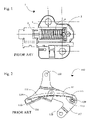
- FIG. 2 shows an example of a blade tensioner.
- the conventional blade tensioner 110 includes a blade shoe 111 made of resin having a curved chain sliding face and numerous blade springs 121 , preferably made of metallic material.
- the blade springs 121 are arranged in layers on the opposite side of the blade shoe 111 from the chain sliding face, and provide spring force to the blade shoe 111 .
- the ends of each spring-shaped blade spring 121 are inserted in the indented portions 114 and 115 , which are formed in the distal portion 112 and proximal portion 113 of the blade shoe 111 , respectively.
- a bracket 117 is provided for mounting the blade tensioner 110 in an engine. Holes 118 and 119 are formed in the bracket 117 , and mounting bolts are inserted into these holes 118 and 119 .
- a sliding face 116 contacts the distal portion of the blade shoe 111 and permits sliding. The slide face 116 is formed on the distal portion of the bracket 117 .
- a pin 120 supports the proximal portion 113 of the blade shoe 111 so that it may move in either direction. The pin 120 is secured on the bracket 117 .
- FIG. 3 shows a chain tensioning device that has a pair of arms 202 , 203 which are joined by a pivot 204 .
- the arms 202 , 203 are urged apart so that arm 203 applies tensioning force to a chain (not shown) by means of a spring 206 loaded cam block 205 .
- a catch disc 209 and rod 208 are arranged to prevent return movement of the spring loaded cam block 205 .
- FIG. 4 shows an example of a tensioner that uses a ratchet device.
- the ratchet tensioner 301 comprises a tensioner housing 307 having a hole 312 for receiving a plunger 308 and a ratchet pawl 317 pivoted by a shaft 316 to the tensioner housing 307 and biased by a ratchet spring 318 .
- the plunger 308 has teeth on one outer side that engage the ratchet pawl 317 .
- the plunger 308 is biased out of the hole 312 to contact the tension lever 310 by fluid in the hollow section 313 and by the plunger spring 314 .
- the tensioner lever 310 pivots on support shaft 309 and has a shoe surface 311 that contacts and applies tension to the slack side of the timing chain 306 wrapped around the camshaft 304 and its sprocket 305 and the crankshaft 302 and its sprocket 303 .
- the plunger's 308 movement in and out of the hole 312 is limited by its teeth and the ratchet pawl 317 that engage them.
- FIG. 5 shows a tensioning device of U.S. Pat. No. 6,599,209.
- the tensioning device 421 includes a one piece supporting body 422 with interconnecting sections 424 in the shape of an open honeycomb joined to a tensioning track 423 .
- the tensioning track 423 is elastically supported by coil spring 425 .
- Mounting holes 420 are used to fixedly mount the tensioner 421 .
- a pair of tensioning tracks 406 are joined by rib like interconnecting sections 407 to form one piece 402 .
- Interconnecting sections 407 are elastically deformable and have angled sections 408 .
- the present invention consists of a tensioner for imparting tension to a chain consisting of a body, a resilient chain guide element, at least one blade spring, and at least one bracket.
- the body of the tensioner has a surface with a profile of the path of a new chain.
- the resilient chain guide element on the surface of the body has a chain contact surface and two ends wrapped around the ends of the body, with the chain guide being sufficiently larger than the body, such that the chain contact surface can be biased away from the body.
- the blade spring is present in the groove with each of its ends in the containment means of the groove, urging the chain guide away from the body and toward the chain.
- the overall length of the tensioner of the present invention is longer than conventional chain tensioners, in excess of five inches.
- the resilient chain guide element is substantially longer than the length of the blade spring.
- FIG. 1 shows a prior art hydraulic tensioner
- FIG. 2 shows a prior art blade tensioner
- FIG. 3 shows another prior art tensioner.
- FIG. 4 shows a prior art ratcheting tensioner.
- FIG. 5 shows a one piece prior art tensioner.
- FIG. 6 a shows an alternate embodiment of a one piece prior art tensioner.
- FIG. 6 b shows another alternate embodiment of a one piece prior art tensioner
- FIG. 7 is a frontal view of the present invention showing a tensioner as it would appear adjacent a new or un-worn chain.
- FIG. 8 shows the tensioner of FIG. 7 with one of the chain guide walls cut away.
- FIG. 9 shows a cut-away of the tensioner of FIG. 8 without the chain.
- FIG. 10 shows the chain guide element, the support member and a blade spring.
- FIG. 11 shows the support member and the blade spring bowed in response to a slack or worn chain.
- FIG. 12 shows an isometric view of the resilient chain guide element.
- FIG. 13 shows an isometric view of the body of the tensioner.
- FIG. 14 shows a frontal view of a second embodiment of the invention consisting of two tensioners.
- FIG. 15 shows an alternate embodiment of the invention in which a single tensioner contains two blade springs.
- FIGS. 7 and 8 show a first embodiment of the tensioner of the present invention with a new chain 500 wrapped around a drive sprocket and at least one driven sprocket (not shown). Positioned adjacent to the outside of the slack strand of the chain 500 is tensioner 502 .
- the tensioner 502 may alternatively be located on the tight strand, if desired.
- a bracket body 504 has a surface 504 c with a curved profile that is similar to the path of a new chain.
- a channel cut groove 506 having a bottom 506 b and containment means in the form of recessed pockets 506 c at either end of the groove 506 is located longitudinally along a portion of the length of the surface 504 c .
- FIG. 13 shows an embodiment where the groove is located substantially equidistant from the first and second ends, 504 a and 504 b , respectively, of bracket body 504 .
- At least one blade spring 510 is placed in the channel cut groove 506 .
- the groove may be located at any point along surface 504 c , as dictated by design and functional parameters.
- the blade spring 510 is an elongated rectangle curled lengthwise in its free state and applied substantially uncurled in its assembled state, into the channel cut groove 506 , between the bracket body 504 and support member 505 .
- Support member 505 is an elongated rectangle consisting of a metallic material that is manufactured to provide spring tension.
- the primary force urging the resilient chain guide element 512 toward the chain 500 is provided by the blade spring 510 .
- the spring tension force exhibited by the support member 505 need only be sufficient to transfer the force of the blade spring 510 so that this force is distributed substantially evenly along the entire length of the resilient chain guide element 512 .
- Recessed pockets 506 c at either end of the groove 506 act as containment means and bearing surfaces for the ends of the blade spring 510 as the blade spring tries to curl into its free state.
- the blade spring 510 exerts a force to the underside support member 505 as the blade spring 510 tries to curl into its free state.
- the inherent nature of the blade spring 510 to return to its resting curled state forces the resilient chain guide element 512 to be in constant contact with and applying a sufficient force to the chain 500 to maintain a substantially constant tension on the chain 500 .
- the surface 504 c of the bracket body 504 acts as a stop for the support member 505 in opposition to excessive force from the chain 500 in the direction of the chain tensioner 502 .
- Chain guide walls 514 a and 514 b are present on either side of the surface 504 c of the bracket body 504 to aid in maintaining the support member 505 and the resilient chain guide element 512 in the “Z” direction when in its extended state, such as when it is in contact with a worn or slack chain.
- the chain guide walls 514 a and 514 b are preferably fixedly attached to the bracket body or alternatively, and preferably, integral to the bracket body 504 .
- Holes 516 a and 516 b are located at opposite ends of the bracket body 504 to receive bolts, rivets or other means (not shown) for rigidly securing the bracket body 504 to the engine block or other appropriate mounting surface.
- the bracket body 504 may also be securely mounted to the engine at a single point, such as at pivot hole 517 . In this embodiment, bracket body 504 would be allowed to pivot around the centerline of pivot hole 517 .
- the resilient chain guide element 512 has a first end 512 c and second end 512 d joined together by a middle portion that acts as the chain sliding face 512 b .
- the chain sliding face 512 b is in slideable contact with the chain 500 .
- guide ridges 512 a are guide ridges 512 a on either side of the chain sliding face 512 b to aid in guiding the chain 500 as shown in FIG. 12 .
- the first end 512 c and the second end 512 d of the resilient chain guide element 512 are curved underneath and towards the center of the resilient chain guide element 512 .
- the chain guide element 512 is larger than the bracket body 504 and the curved first end 512 c and second end 512 d of the resilient chain guide element 512 receive the respective first end 504 a and second end 504 b of the bracket body 504 , loosely securing the resilient chain guide element 512 to the bracket body 504 .
- the resilient chain guide element 512 is preferably made of a material that is semi-flexible at engine operating temperatures, allowing the resilient chain guide element 512 to conform to the chain 500 in response to the urging force of the blade spring 510 that is transmitted through support member 505 .
- the tensioner 502 is placed relative to the slack strand of a new chain, so that the strand is received between the pair of chain guide walls 514 a , 514 b and slides on the chain sliding face 512 b of the resilient chain guide element 512 . Since the resilient chain guide element 512 of the tensioner 502 is semi-flexible at engine operating temperatures, the force exerted by the blade spring 510 biases the support member 505 and the resilient chain guide element 512 away from the bracket body 504 such that the chain sliding face 512 b conforms to and maintains constant contact with the strand of chain 500 .
- the length of the blade spring 510 is significantly shorter than the length of the support member 505 .
- the ratio of the length of the blade spring 510 to the support member 505 is from about 1:2 to about 1:6.
- the ratio is from about 1:3 to about 1:4.
- FIG. 11 shows the section cut resilient chain guide element 512 and the support member 505 with the blade spring 510 in its free state.
- the blade spring 510 will respond to a worn or slack chain by curving or bowing more than a blade spring 510 adjacent a new or tight chain. As the chain wears and elongates, the blade spring becomes more bowed to forcibly urge support member 505 and the resilient chain guide element 512 to exert a force on the chain sufficient to remove slack in the strand.
- Blade spring 510 consists of conventional spring material in a generally elongated rectangular shape that is curled lengthwise in its free state. As it is installed in the groove 506 of bracket body 504 , it is compressed between the support member 505 and the bracket body 504 , thus exerting a force on the resilient chain guide element 512 that urges it into forceable contact with the chain 500 . Due to the relatively short length of the blade spring 510 , it is able to exert a substantially constant force on support member 505 as the resilient chain guide element 512 travels the distance between the points of contact with the strand of chain 500 that alternates between slack and tight chain conditions.
- Groove 506 may be as wide as the width of surface 504 c between chain guide walls 514 a and 514 b . In the alternative, the width of groove 506 may be less than the width of surface 504 c if it is deemed necessary to provide a continuity of support for support member 505 along the entire length of surface 504 c.
- FIG. 14 shows a second embodiment of the present invention.
- a first tensioner 502 is located on the slack strand and a second tensioner 602 is located on the tight strand of the chain 500 .
- the first tensioner and the second tensioner can be exactly the same and have the same corresponding elements as described hereinabove with respect to the first embodiment.
- the blade spring in the first tensioner on one strand may exert a stronger force than the blade spring in the second tensioner.
- FIG. 15 shows an alternate embodiment of the invention.
- two blade springs 510 and 510 a are positioned in series along surface 504 c of a single bracket body 504 within separate channel cut grooves 506 and 506 a .
- each of the two blade springs 506 and 506 a apply their respective forces at two different locations along the length of resilient chain guide element 512 .
- the blade springs may be designed to approximately divide the length of the bracket body 504 into thirds or they may be placed in an asymmetrical arrangement along the length, as desired.
- one blade spring may be located at approximately the mid point of the length with the second blade spring located at a point approximately equidistant from the mid point of the bracket body and one of its ends.
- a third blade spring that would be located approximately equidistant from the mid point of the bracket body and its other end.
Landscapes
- Engineering & Computer Science (AREA)
- General Engineering & Computer Science (AREA)
- Mechanical Engineering (AREA)
- Devices For Conveying Motion By Means Of Endless Flexible Members (AREA)
Priority Applications (5)
| Application Number | Priority Date | Filing Date | Title |
|---|---|---|---|
| US11/204,306 US7597640B2 (en) | 2005-08-15 | 2005-08-15 | Long mechanical tensioner with a compliant blade spring |
| DE602006021432T DE602006021432D1 (de) | 2005-08-15 | 2006-07-25 | Langer mechanischer spanner mit nachgiebiger blattfeder |
| EP06788429A EP1915549B1 (de) | 2005-08-15 | 2006-07-25 | Langer mechanischer spanner mit nachgiebiger blattfeder |
| JP2008526950A JP4968801B2 (ja) | 2005-08-15 | 2006-07-25 | 追従性ブレードスプリングを備えた長尺の機械式テンショナ |
| PCT/US2006/028838 WO2007021470A1 (en) | 2005-08-15 | 2006-07-25 | Long mechanical tensioner with a compliant blade spring |
Applications Claiming Priority (1)
| Application Number | Priority Date | Filing Date | Title |
|---|---|---|---|
| US11/204,306 US7597640B2 (en) | 2005-08-15 | 2005-08-15 | Long mechanical tensioner with a compliant blade spring |
Publications (2)
| Publication Number | Publication Date |
|---|---|
| US20070037647A1 US20070037647A1 (en) | 2007-02-15 |
| US7597640B2 true US7597640B2 (en) | 2009-10-06 |
Family
ID=37068246
Family Applications (1)
| Application Number | Title | Priority Date | Filing Date |
|---|---|---|---|
| US11/204,306 Active 2028-01-13 US7597640B2 (en) | 2005-08-15 | 2005-08-15 | Long mechanical tensioner with a compliant blade spring |
Country Status (5)
| Country | Link |
|---|---|
| US (1) | US7597640B2 (de) |
| EP (1) | EP1915549B1 (de) |
| JP (1) | JP4968801B2 (de) |
| DE (1) | DE602006021432D1 (de) |
| WO (1) | WO2007021470A1 (de) |
Cited By (7)
| Publication number | Priority date | Publication date | Assignee | Title |
|---|---|---|---|---|
| US20090275430A1 (en) * | 2006-02-17 | 2009-11-05 | Borgwarner Inc. | Force limiting tensioning arm |
| US20150204218A1 (en) * | 2014-01-21 | 2015-07-23 | Tsubakimoto Chain Co. | Guide shoe |
| US20170276216A1 (en) * | 2014-10-02 | 2017-09-28 | Iwis Motorsysteme Gmbh & Co. Kg | Chain drive having a plurality of sliding elements |
| US20180038459A1 (en) * | 2016-08-04 | 2018-02-08 | Tsubakimoto Chain Co. | Chain drive device and chain guide |
| US10378619B2 (en) * | 2015-07-08 | 2019-08-13 | Iwis Motorsysteme Gmbh & Co. Kg | Modular guide rail or modular tensioning rail |
| US11796040B2 (en) | 2021-01-22 | 2023-10-24 | Borgwarner Inc. | Method(s) to apply tension to increase drivetrain jump torque capacity |
| US12078245B2 (en) | 2022-05-31 | 2024-09-03 | Borgwarner Inc. | Face of tensioner guide or arm with pattern to influence chain system NVH performance |
Families Citing this family (10)
| Publication number | Priority date | Publication date | Assignee | Title |
|---|---|---|---|---|
| JP5309028B2 (ja) * | 2006-08-11 | 2013-10-09 | ボーグワーナー インコーポレーテッド | 緊張されたチェーン駆動システム用のアセンブリシステムおよび方法 |
| EP2603717B1 (de) | 2010-08-09 | 2015-02-11 | Cloyes Gear and Products, Inc. | Blattspanner mit federhaltemechanismus |
| JP5681562B2 (ja) * | 2011-05-19 | 2015-03-11 | 本田技研工業株式会社 | チェーンテンショナー装置 |
| JP5997022B2 (ja) * | 2012-11-29 | 2016-09-21 | 株式会社椿本チエイン | チェーンガイド |
| WO2014089575A1 (en) | 2012-12-09 | 2014-06-12 | Cloyes Gear And Products, Inc. | Chain tensioner |
| DE102013004456B3 (de) * | 2013-03-14 | 2014-09-18 | Iwis Motorsysteme Gmbh & Co. Kg | Spannschiene mit federndem Aufdrückbereich |
| US9307508B2 (en) * | 2013-04-29 | 2016-04-05 | Google Technology Holdings LLC | Systems and methods for syncronizing multiple electronic devices |
| WO2016144959A1 (en) | 2015-03-09 | 2016-09-15 | Cloyes Gear And Products, Inc. | Chain tensioner plastic blade with improved structural rigidity at the spring-end reaction surfaces of the blade |
| CN109654183A (zh) | 2017-10-12 | 2019-04-19 | 博格华纳公司 | 具有可调节止回阀的液压张紧器 |
| TWI752306B (zh) * | 2019-03-20 | 2022-01-11 | 彥豪金屬工業股份有限公司 | 自行車變速器 |
Citations (26)
| Publication number | Priority date | Publication date | Assignee | Title |
|---|---|---|---|---|
| FR827707A (fr) | 1936-11-30 | 1938-05-03 | Perfectionnements aux dispositifs de tension pour chaînes de transmission et applications analogues | |
| GB505746A (en) | 1937-10-11 | 1939-05-11 | John Weller | Improvements in tensioning devices for transmission chains and the like |
| GB1290279A (de) | 1970-06-19 | 1972-09-27 | ||
| GB2022762A (en) * | 1978-06-07 | 1979-12-19 | Shiroyama Kogyo Kk | Chain Tensioners |
| US4395251A (en) | 1980-02-11 | 1983-07-26 | Borg-Warner Limited | Tensioning devices |
| JPH03153945A (ja) | 1989-11-08 | 1991-07-01 | Honda Motor Co Ltd | チェーンテンショナ |
| US5266066A (en) * | 1992-08-21 | 1993-11-30 | Borg-Warner Automative, Inc. | Spring blade chain tensioner |
| US5797818A (en) | 1996-04-02 | 1998-08-25 | Cloyes Gear And Products, Inc. | Chain tensioner with damping feature |
| US5967921A (en) | 1997-10-09 | 1999-10-19 | Borg-Warner Automotive, Inc. | Hydraulic chain tensioner with molded plastic body |
| US5984815A (en) * | 1997-03-28 | 1999-11-16 | Morse Tec Europe S.P.A. | Spring blade tensioner with curved blade ends |
| US6155941A (en) | 1998-12-15 | 2000-12-05 | Borgwarner Inc. | Hydraulic tensioner having a flexible blade arm |
| EP1070875A2 (de) | 1999-07-22 | 2001-01-24 | Borg-Warner Automotive K. K. | Kettenspannvorrichtung mit Blattfeder |
| EP1164312A2 (de) | 2000-06-15 | 2001-12-19 | Borg-Warner Automotive K. K. | Spannvorrichtung mit Blattfeder |
| US6364796B1 (en) * | 1999-02-16 | 2002-04-02 | Borg-Warner Automotive K.K. | Blade chain tensioner |
| US6375587B1 (en) | 1999-11-12 | 2002-04-23 | Borgwarner Inc. | Timing chain having multiple blade tensioners contacting the same section of chain |
| US6478703B2 (en) | 2000-02-02 | 2002-11-12 | Tsubakimoto Chain Co. | Ratchet tensioner with backlash |
| US20020198073A1 (en) * | 2001-05-17 | 2002-12-26 | Hiroyuki Takeda | Blade tensioner and system for a chain |
| US6599209B1 (en) | 1999-05-26 | 2003-07-29 | Ina-Schaeffler Kg | Tensioning device for tensioning a traction medium |
| US6609986B1 (en) | 1999-11-12 | 2003-08-26 | Borgwarner Inc. | Mechanical tensioner comprised of a rigid arm urged against chain by at least one blade type spring |
| US6623391B2 (en) | 2000-10-17 | 2003-09-23 | Cloyes Gear And Products, Inc. | Blade-type mechanical chain tensioner with external strengthening rib |
| JP2004278621A (ja) | 2003-03-14 | 2004-10-07 | Daido Kogyo Co Ltd | 板バネ式テンショナー装置 |
| US20050085322A1 (en) * | 2003-10-15 | 2005-04-21 | Borgwarner Inc. | Pivoting chain guide and tensioner assembly |
| EP1526306A2 (de) | 2003-10-23 | 2005-04-27 | BorgWarner Inc. | Biegsame Kettenführungsschiene mit Blattfeder |
| US6939259B2 (en) * | 2003-04-25 | 2005-09-06 | Borgwarner Inc. | Two-shot unified chain tensioner arm or guide |
| US6955621B2 (en) * | 2001-04-26 | 2005-10-18 | Borgwarner Inc. | Rotary actuating hydraulic tensioner |
| US7014585B2 (en) * | 2001-12-28 | 2006-03-21 | Borgwarner Morse Tec Japan K.K. | Blade-type chain tensioner system |
Family Cites Families (4)
| Publication number | Priority date | Publication date | Assignee | Title |
|---|---|---|---|---|
| JPS6227736Y2 (de) * | 1980-02-16 | 1987-07-16 | ||
| JP2002089636A (ja) * | 2000-09-13 | 2002-03-27 | Toyota Motor Corp | 環状帯システムのガイド機構 |
| JP3755132B2 (ja) * | 2001-12-27 | 2006-03-15 | ボルグワーナー・モールステック・ジャパン株式会社 | チェーン用ブレードテンショナシステム |
| JP2005155795A (ja) * | 2003-11-26 | 2005-06-16 | Borg Warner Morse Tec Japan Kk | ブレードテンショナ |
-
2005
- 2005-08-15 US US11/204,306 patent/US7597640B2/en active Active
-
2006
- 2006-07-25 DE DE602006021432T patent/DE602006021432D1/de active Active
- 2006-07-25 EP EP06788429A patent/EP1915549B1/de not_active Not-in-force
- 2006-07-25 JP JP2008526950A patent/JP4968801B2/ja not_active Expired - Fee Related
- 2006-07-25 WO PCT/US2006/028838 patent/WO2007021470A1/en active Application Filing
Patent Citations (26)
| Publication number | Priority date | Publication date | Assignee | Title |
|---|---|---|---|---|
| FR827707A (fr) | 1936-11-30 | 1938-05-03 | Perfectionnements aux dispositifs de tension pour chaînes de transmission et applications analogues | |
| GB505746A (en) | 1937-10-11 | 1939-05-11 | John Weller | Improvements in tensioning devices for transmission chains and the like |
| GB1290279A (de) | 1970-06-19 | 1972-09-27 | ||
| GB2022762A (en) * | 1978-06-07 | 1979-12-19 | Shiroyama Kogyo Kk | Chain Tensioners |
| US4395251A (en) | 1980-02-11 | 1983-07-26 | Borg-Warner Limited | Tensioning devices |
| JPH03153945A (ja) | 1989-11-08 | 1991-07-01 | Honda Motor Co Ltd | チェーンテンショナ |
| US5266066A (en) * | 1992-08-21 | 1993-11-30 | Borg-Warner Automative, Inc. | Spring blade chain tensioner |
| US5797818A (en) | 1996-04-02 | 1998-08-25 | Cloyes Gear And Products, Inc. | Chain tensioner with damping feature |
| US5984815A (en) * | 1997-03-28 | 1999-11-16 | Morse Tec Europe S.P.A. | Spring blade tensioner with curved blade ends |
| US5967921A (en) | 1997-10-09 | 1999-10-19 | Borg-Warner Automotive, Inc. | Hydraulic chain tensioner with molded plastic body |
| US6155941A (en) | 1998-12-15 | 2000-12-05 | Borgwarner Inc. | Hydraulic tensioner having a flexible blade arm |
| US6364796B1 (en) * | 1999-02-16 | 2002-04-02 | Borg-Warner Automotive K.K. | Blade chain tensioner |
| US6599209B1 (en) | 1999-05-26 | 2003-07-29 | Ina-Schaeffler Kg | Tensioning device for tensioning a traction medium |
| EP1070875A2 (de) | 1999-07-22 | 2001-01-24 | Borg-Warner Automotive K. K. | Kettenspannvorrichtung mit Blattfeder |
| US6609986B1 (en) | 1999-11-12 | 2003-08-26 | Borgwarner Inc. | Mechanical tensioner comprised of a rigid arm urged against chain by at least one blade type spring |
| US6375587B1 (en) | 1999-11-12 | 2002-04-23 | Borgwarner Inc. | Timing chain having multiple blade tensioners contacting the same section of chain |
| US6478703B2 (en) | 2000-02-02 | 2002-11-12 | Tsubakimoto Chain Co. | Ratchet tensioner with backlash |
| EP1164312A2 (de) | 2000-06-15 | 2001-12-19 | Borg-Warner Automotive K. K. | Spannvorrichtung mit Blattfeder |
| US6623391B2 (en) | 2000-10-17 | 2003-09-23 | Cloyes Gear And Products, Inc. | Blade-type mechanical chain tensioner with external strengthening rib |
| US6955621B2 (en) * | 2001-04-26 | 2005-10-18 | Borgwarner Inc. | Rotary actuating hydraulic tensioner |
| US20020198073A1 (en) * | 2001-05-17 | 2002-12-26 | Hiroyuki Takeda | Blade tensioner and system for a chain |
| US7014585B2 (en) * | 2001-12-28 | 2006-03-21 | Borgwarner Morse Tec Japan K.K. | Blade-type chain tensioner system |
| JP2004278621A (ja) | 2003-03-14 | 2004-10-07 | Daido Kogyo Co Ltd | 板バネ式テンショナー装置 |
| US6939259B2 (en) * | 2003-04-25 | 2005-09-06 | Borgwarner Inc. | Two-shot unified chain tensioner arm or guide |
| US20050085322A1 (en) * | 2003-10-15 | 2005-04-21 | Borgwarner Inc. | Pivoting chain guide and tensioner assembly |
| EP1526306A2 (de) | 2003-10-23 | 2005-04-27 | BorgWarner Inc. | Biegsame Kettenführungsschiene mit Blattfeder |
Cited By (11)
| Publication number | Priority date | Publication date | Assignee | Title |
|---|---|---|---|---|
| US20090275430A1 (en) * | 2006-02-17 | 2009-11-05 | Borgwarner Inc. | Force limiting tensioning arm |
| US8052558B2 (en) * | 2006-02-17 | 2011-11-08 | Borgwarner Inc. | Force limiting tensioning arm |
| US20150204218A1 (en) * | 2014-01-21 | 2015-07-23 | Tsubakimoto Chain Co. | Guide shoe |
| US9534516B2 (en) * | 2014-01-21 | 2017-01-03 | Tsubakimoto Chain Co. | Guide shoe |
| US20170276216A1 (en) * | 2014-10-02 | 2017-09-28 | Iwis Motorsysteme Gmbh & Co. Kg | Chain drive having a plurality of sliding elements |
| US10495193B2 (en) * | 2014-10-02 | 2019-12-03 | Iwis Motorsysteme Gmbh & Co. Kg | Chain drive having a plurality of sliding elements |
| US10378619B2 (en) * | 2015-07-08 | 2019-08-13 | Iwis Motorsysteme Gmbh & Co. Kg | Modular guide rail or modular tensioning rail |
| US20180038459A1 (en) * | 2016-08-04 | 2018-02-08 | Tsubakimoto Chain Co. | Chain drive device and chain guide |
| US10502288B2 (en) * | 2016-08-04 | 2019-12-10 | Tsubakimoto Chain Co. | Chain drive device and chain guide |
| US11796040B2 (en) | 2021-01-22 | 2023-10-24 | Borgwarner Inc. | Method(s) to apply tension to increase drivetrain jump torque capacity |
| US12078245B2 (en) | 2022-05-31 | 2024-09-03 | Borgwarner Inc. | Face of tensioner guide or arm with pattern to influence chain system NVH performance |
Also Published As
| Publication number | Publication date |
|---|---|
| JP4968801B2 (ja) | 2012-07-04 |
| EP1915549B1 (de) | 2011-04-20 |
| WO2007021470A1 (en) | 2007-02-22 |
| JP2009505020A (ja) | 2009-02-05 |
| DE602006021432D1 (de) | 2011-06-01 |
| EP1915549A1 (de) | 2008-04-30 |
| US20070037647A1 (en) | 2007-02-15 |
Similar Documents
| Publication | Publication Date | Title |
|---|---|---|
| US7597640B2 (en) | Long mechanical tensioner with a compliant blade spring | |
| US7641577B2 (en) | Mechanical chain tensioner with compliant blade spring | |
| US7479077B2 (en) | Pivoting mechanical tensioner with compliant blade spring | |
| EP1984649B1 (de) | Spannarm zur kraftbegrenzung | |
| US8066600B2 (en) | Ratchet mechanism for a chain drive | |
| US7628719B2 (en) | Mechanical strap tensioner for multi-strand tensioning | |
| US7455606B2 (en) | Mechanical chain tensioner with a rotational ratcheting device | |
| US7537533B2 (en) | Chain tensioning device linking two strands of a chain drive | |
| US20110077114A1 (en) | Anchored mechanical strap tensioner for multi-strand tensioning | |
| US20060293133A1 (en) | Dual pivoting pawl tensioner |
Legal Events
| Date | Code | Title | Description |
|---|---|---|---|
| AS | Assignment |
Owner name: BORGWARNER INC., MICHIGAN Free format text: ASSIGNMENT OF ASSIGNORS INTEREST;ASSIGNORS:MARKLEY, GEORGE L;CAPP, JAMES;WIGSTEN, MARK M;REEL/FRAME:016441/0840;SIGNING DATES FROM 20050809 TO 20050810 |
|
| FEPP | Fee payment procedure |
Free format text: PAYOR NUMBER ASSIGNED (ORIGINAL EVENT CODE: ASPN); ENTITY STATUS OF PATENT OWNER: LARGE ENTITY |
|
| STCF | Information on status: patent grant |
Free format text: PATENTED CASE |
|
| CC | Certificate of correction | ||
| FPAY | Fee payment |
Year of fee payment: 4 |
|
| FPAY | Fee payment |
Year of fee payment: 8 |
|
| MAFP | Maintenance fee payment |
Free format text: PAYMENT OF MAINTENANCE FEE, 12TH YEAR, LARGE ENTITY (ORIGINAL EVENT CODE: M1553); ENTITY STATUS OF PATENT OWNER: LARGE ENTITY Year of fee payment: 12 |