US7578324B2 - Self-centering tool - Google Patents
Self-centering tool Download PDFInfo
- Publication number
- US7578324B2 US7578324B2 US10/835,894 US83589404A US7578324B2 US 7578324 B2 US7578324 B2 US 7578324B2 US 83589404 A US83589404 A US 83589404A US 7578324 B2 US7578324 B2 US 7578324B2
- Authority
- US
- United States
- Prior art keywords
- post
- housing
- bit
- extended position
- disposed
- Prior art date
- Legal status (The legal status is an assumption and is not a legal conclusion. Google has not performed a legal analysis and makes no representation as to the accuracy of the status listed.)
- Expired - Lifetime
Links
- 238000004873 anchoring Methods 0.000 claims abstract description 6
- 238000005553 drilling Methods 0.000 claims description 11
- 239000002023 wood Substances 0.000 description 16
- 230000008901 benefit Effects 0.000 description 2
- 230000006378 damage Effects 0.000 description 2
- 230000000717 retained effect Effects 0.000 description 2
- 208000027418 Wounds and injury Diseases 0.000 description 1
- 230000008878 coupling Effects 0.000 description 1
- 238000010168 coupling process Methods 0.000 description 1
- 238000005859 coupling reaction Methods 0.000 description 1
- 208000014674 injury Diseases 0.000 description 1
- 239000000463 material Substances 0.000 description 1
- 230000000452 restraining effect Effects 0.000 description 1
- ITMCEJHCFYSIIV-UHFFFAOYSA-M triflate Chemical compound [O-]S(=O)(=O)C(F)(F)F ITMCEJHCFYSIIV-UHFFFAOYSA-M 0.000 description 1
- 239000002699 waste material Substances 0.000 description 1
Images


Classifications
-
- B—PERFORMING OPERATIONS; TRANSPORTING
- B23—MACHINE TOOLS; METAL-WORKING NOT OTHERWISE PROVIDED FOR
- B23B—TURNING; BORING
- B23B51/00—Tools for drilling machines
- B23B51/04—Drills for trepanning
- B23B51/0426—Drills for trepanning with centering devices
-
- B—PERFORMING OPERATIONS; TRANSPORTING
- B23—MACHINE TOOLS; METAL-WORKING NOT OTHERWISE PROVIDED FOR
- B23B—TURNING; BORING
- B23B51/00—Tools for drilling machines
- B23B51/04—Drills for trepanning
- B23B51/044—Drills for trepanning with core holding devices
-
- Y—GENERAL TAGGING OF NEW TECHNOLOGICAL DEVELOPMENTS; GENERAL TAGGING OF CROSS-SECTIONAL TECHNOLOGIES SPANNING OVER SEVERAL SECTIONS OF THE IPC; TECHNICAL SUBJECTS COVERED BY FORMER USPC CROSS-REFERENCE ART COLLECTIONS [XRACs] AND DIGESTS
- Y10—TECHNICAL SUBJECTS COVERED BY FORMER USPC
- Y10T—TECHNICAL SUBJECTS COVERED BY FORMER US CLASSIFICATION
- Y10T408/00—Cutting by use of rotating axially moving tool
- Y10T408/89—Tool or Tool with support
- Y10T408/893—Hollow milling Tool
-
- Y—GENERAL TAGGING OF NEW TECHNOLOGICAL DEVELOPMENTS; GENERAL TAGGING OF CROSS-SECTIONAL TECHNOLOGIES SPANNING OVER SEVERAL SECTIONS OF THE IPC; TECHNICAL SUBJECTS COVERED BY FORMER USPC CROSS-REFERENCE ART COLLECTIONS [XRACs] AND DIGESTS
- Y10—TECHNICAL SUBJECTS COVERED BY FORMER USPC
- Y10T—TECHNICAL SUBJECTS COVERED BY FORMER US CLASSIFICATION
- Y10T408/00—Cutting by use of rotating axially moving tool
- Y10T408/89—Tool or Tool with support
- Y10T408/895—Having axial, core-receiving central portion
Definitions
- the present invention relates generally to wood working tools and, in particular, to plug cutters.
- Wooden plugs are often used to fill holes in a workpiece to conceal fasteners and screws that have been set below the surface of the workpiece.
- a wooden plug having a length greater than the depth of the cavity in which the fastener is seated is cut from a section of wood. The plug is then glued within the cavity and the section of the plug extending from the workpiece is trimmed and sanded, such that the plug is flush with the workpiece to conceal the fastener.
- plug cutters include a plurality of cutting surfaces adapted to cut a shaped plug from wood. The plug cutter is pressed against a piece of wood and drilled to form the shaped plug. The plug is then removed from the piece of wood by chipping or cutting wood away from the base of the plug. Although such plug cutters are effective at cutting wooden plugs, they are not without their problems.
- existing plug cutters when initially cutting wood to form a plug, may spin along the surface of the wood before the cutting prongs are set within the wood. This is also true if a tool operator uses a hand drill to drive the plug cutter. As a result, and regardless of whether a drill press or a hand drill is used to drive the plug cutter, existing plug cutters are potentially dangerous to the tool operator as the plug cutter may slide across the surface of the wood until and unless the plug cutter is set within the wood. Also, such sliding motion damages the surface of the wood, thereby resulting in waste wood product.
- plug cutters are effective at cutting wood plugs, there exists a need for improved plug cutters that assist in retaining the plug cutter in a localized area of the wood during initial cutting of the plug.
- a bit for a tool includes a housing having a cutting portion and a shank.
- the bit also includes a post disposed within the housing and positioned to assist in anchoring the bit to a workpiece during use.
- the bit includes a biasing member disposed within the housing and positioned to urge the post into an extended position.
- a bit for a tool includes a housing having a cutting portion and a shank, and a post.
- the post is slidably disposed within the housing and is positioned to assist in retaining the bit in a localized area of a workpiece during use.
- the bit further includes a biasing member disposed within the housing and positioned to reciprocate the post between an extended position and a retracted position in response to a drilling pressure applied to the bit.
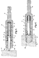
- FIG. 1 is an isometric view of a bit for a tool formed in accordance with one embodiment of the present invention
- FIG. 2 is an exploded, isometric view of the bit of FIG. 1 ;
- FIG. 3 is a cross-sectional, side planar view of the bit of FIG. 1 showing the post in an extended position;
- FIG. 4 is a cross-sectional, side planar view of the bit of FIG. 3 , showing the post in a retracted position;
- FIG. 5 is an isometric view of a bit for a tool formed in accordance with a second embodiment of the present invention.
- FIG. 1 illustrates a plug cutter 20 formed in accordance with one embodiment of the present invention.
- the plug cutter 20 includes a housing 22 having a cutting portion 24 formed at one end and a shank 26 formed at the other end of the housing 22 .
- the cutting portion 24 includes a plurality of cutting tines 30 a - 30 d .
- the cutting tines 30 a - 30 d are suitably disposed around a perimeter of the housing 22 .
- the shank 26 is suitably integrally formed with the housing 22 and is sized and constructed in a well-known shape, such as a hex shank, for coupling to a hand drill (not shown) or table mounted drill press (not shown).
- a hand drill not shown
- table mounted drill press not shown
- the shank 26 is geometrically illustrated as a hex-shaped shank, other geometries are also within the scope of the present invention.
- the geometry of the shank 26 could be flat, round, tri-flat, square, polygonal, or splined.
- such geometrically shaped shanks are also within the scope of the present invention.
- the housing 22 is illustrated and described as having an integrally formed shank 26 , other types of housing, such as a multi-piece housing, are also within the scope of the present invention.
- the plug cutter 20 includes a post 40 slidably disposed within a cavity 21 of the housing 22 on a biasing member 42 , such as a helical spring.
- a biasing member 42 such as a helical spring
- the biasing member 42 is illustrated as a helical spring, it should be apparent that other types of biasing members are also within the scope of the present invention.
- an elastomeric spring or a plurality of springs are also within the scope of equivalent structures for a biasing member of the present invention. Accordingly, other types of biasing members, and their structural equivalents, are also within the scope of the present invention.
- the cavity 21 extends partially through the longitudinal direction of the housing 22 .
- the cavity 21 is sized and geometrically shaped to receive the post 40 therein.
- the post 40 is retained within the housing 22 by a retaining collar 44 , a round spring 46 , and a washer 48 .
- the post 40 includes a pointed retaining end 50 for assisting in restraining or centering the plug cutter 20 relative to a workpiece during use, as is described in greater detail below.
- the post 40 is slidably or reciprocally mounted within the cavity 21 of the housing 22 on the biasing member 42 .
- the washer 48 is disposed between one end of the biasing member 42 and a face of a shoulder 51 extending around the perimeter of one end of the post 40 .
- the retaining collar 44 is slidably received and seated against a stepped annular shoulder 53 integrally formed within the cavity 21 .
- the retaining collar 44 is thus positioned to retain the post 40 within the housing 22 during use and illustrated in FIG. 3 .
- the retaining collar 44 is suitably retained within the cavity 21 by the round spring 46 .
- the post 40 is slidably received within the cavity 21 , and the biasing member 42 assists in reciprocating the post 40 between an extended and retracted position.
- FIGS. 3 and 4 Operation of the plug cutter 20 may be best understood by referring to FIGS. 3 and 4 .
- the plug cutter 20 is shown in the extended position, wherein the retaining end 50 of the post 40 is partially received within a workpiece 52 , such as a section of wood.
- the post 40 assists in retaining and/or centering the plug cutter 20 relative to the workpiece 52 during initial and continued drilling of the plug cutter 20 into the workpiece 52 .
- the plug 40 is displaced into a retracted position ( FIG. 4 ) within the cavity 21 of the housing 22 in response to a drilling pressure applied to the plug cutter 20 . Because of the interference of the retaining end 50 of the plug 40 with the workpiece 52 during drilling operation of the plug cutter 20 , the post 40 assists in retaining and/or centering the plug cutter 20 relative to the workpiece 52 to minimize the risk of injury to a drill operator.
- a plug cutter 120 formed in accordance with a second embodiment of the present invention will now be described in greater detail.
- the plug cutter 120 is identical in materials and operation to the embodiments described above with the exception that the plurality of cutting tines 30 a - 30 d formed with the housing 22 have been replaced with a single, radially-shaped cutting surface 130 .
- Such a cutting surface is well known in the art.
Landscapes
- Engineering & Computer Science (AREA)
- Mechanical Engineering (AREA)
- Constituent Portions Of Griding Lathes, Driving, Sensing And Control (AREA)
- Drilling And Boring (AREA)
- Processing Of Stones Or Stones Resemblance Materials (AREA)
Priority Applications (3)
| Application Number | Priority Date | Filing Date | Title |
|---|---|---|---|
| US10/835,894 US7578324B2 (en) | 2003-04-30 | 2004-04-30 | Self-centering tool |
| US11/282,309 US20060120815A1 (en) | 2003-04-30 | 2005-11-17 | Self-centering tool |
| US11/686,899 US20080075548A1 (en) | 2003-04-30 | 2007-03-15 | Self-centering tool |
Applications Claiming Priority (2)
| Application Number | Priority Date | Filing Date | Title |
|---|---|---|---|
| US46726903P | 2003-04-30 | 2003-04-30 | |
| US10/835,894 US7578324B2 (en) | 2003-04-30 | 2004-04-30 | Self-centering tool |
Related Child Applications (1)
| Application Number | Title | Priority Date | Filing Date |
|---|---|---|---|
| US11/282,309 Continuation-In-Part US20060120815A1 (en) | 2003-04-30 | 2005-11-17 | Self-centering tool |
Publications (2)
| Publication Number | Publication Date |
|---|---|
| US20040218988A1 US20040218988A1 (en) | 2004-11-04 |
| US7578324B2 true US7578324B2 (en) | 2009-08-25 |
Family
ID=33435045
Family Applications (1)
| Application Number | Title | Priority Date | Filing Date |
|---|---|---|---|
| US10/835,894 Expired - Lifetime US7578324B2 (en) | 2003-04-30 | 2004-04-30 | Self-centering tool |
Country Status (3)
| Country | Link |
|---|---|
| US (1) | US7578324B2 (fr) |
| CA (1) | CA2519716C (fr) |
| WO (1) | WO2004098846A2 (fr) |
Cited By (2)
| Publication number | Priority date | Publication date | Assignee | Title |
|---|---|---|---|---|
| US20100278601A1 (en) * | 2007-12-11 | 2010-11-04 | Andrew Mark Beynon | Cutting Apparatus |
| US10549355B1 (en) * | 2012-12-21 | 2020-02-04 | Eric Wayne Parker | Lug nut removal tool |
Families Citing this family (3)
| Publication number | Priority date | Publication date | Assignee | Title |
|---|---|---|---|---|
| US7210382B2 (en) * | 2005-08-15 | 2007-05-01 | Eastway Fair Company Ltd. | Screw guide device |
| WO2015065896A1 (fr) | 2013-11-01 | 2015-05-07 | Milwaukee Electric Tool Corporation | Broche de guidage pour perceuse à colonne |
| CN106335488A (zh) * | 2016-05-17 | 2017-01-18 | 湖南吉利汽车部件有限公司 | 手刹快速调整工装和手刹调整的方法 |
Citations (9)
| Publication number | Priority date | Publication date | Assignee | Title |
|---|---|---|---|---|
| US2484150A (en) * | 1946-12-10 | 1949-10-11 | Brown Robert Lee | Work-expelling device for tubular saws |
| US4129401A (en) * | 1976-07-07 | 1978-12-12 | Manufacture De Vilebrequins De Lorette S.A. | Hole-cutting tool with a free central portion and ejector apparatus for the core of metal formed by the tool |
| US4408935A (en) * | 1980-12-10 | 1983-10-11 | Kabushiki Kaisha Miyanaga | Metal borer |
| US4490080A (en) * | 1983-02-18 | 1984-12-25 | Precision Industries, Inc. | Hole cutting tool |
| US5062748A (en) * | 1991-04-15 | 1991-11-05 | Odsk Company, Limited | Shank structure for annular hole cutter |
| US5205685A (en) * | 1992-10-05 | 1993-04-27 | Herbert Henry R | Hole saw |
| US5316418A (en) * | 1992-09-21 | 1994-05-31 | Kabushiki Kaisha Miyanaga | Hole cutter |
| US5435672A (en) * | 1994-08-05 | 1995-07-25 | Vermont American Corporation | Hole saw having plug ejection feature |
| US5810524A (en) * | 1996-08-01 | 1998-09-22 | Woodworker's Supply, Inc. | Plug cutter with radial relief |
-
2004
- 2004-04-30 CA CA002519716A patent/CA2519716C/fr not_active Expired - Fee Related
- 2004-04-30 US US10/835,894 patent/US7578324B2/en not_active Expired - Lifetime
- 2004-04-30 WO PCT/US2004/013501 patent/WO2004098846A2/fr active Application Filing
Patent Citations (9)
| Publication number | Priority date | Publication date | Assignee | Title |
|---|---|---|---|---|
| US2484150A (en) * | 1946-12-10 | 1949-10-11 | Brown Robert Lee | Work-expelling device for tubular saws |
| US4129401A (en) * | 1976-07-07 | 1978-12-12 | Manufacture De Vilebrequins De Lorette S.A. | Hole-cutting tool with a free central portion and ejector apparatus for the core of metal formed by the tool |
| US4408935A (en) * | 1980-12-10 | 1983-10-11 | Kabushiki Kaisha Miyanaga | Metal borer |
| US4490080A (en) * | 1983-02-18 | 1984-12-25 | Precision Industries, Inc. | Hole cutting tool |
| US5062748A (en) * | 1991-04-15 | 1991-11-05 | Odsk Company, Limited | Shank structure for annular hole cutter |
| US5316418A (en) * | 1992-09-21 | 1994-05-31 | Kabushiki Kaisha Miyanaga | Hole cutter |
| US5205685A (en) * | 1992-10-05 | 1993-04-27 | Herbert Henry R | Hole saw |
| US5435672A (en) * | 1994-08-05 | 1995-07-25 | Vermont American Corporation | Hole saw having plug ejection feature |
| US5810524A (en) * | 1996-08-01 | 1998-09-22 | Woodworker's Supply, Inc. | Plug cutter with radial relief |
Cited By (3)
| Publication number | Priority date | Publication date | Assignee | Title |
|---|---|---|---|---|
| US20100278601A1 (en) * | 2007-12-11 | 2010-11-04 | Andrew Mark Beynon | Cutting Apparatus |
| US8858133B2 (en) * | 2007-12-11 | 2014-10-14 | C4 Carbides Limited | Cutting apparatus |
| US10549355B1 (en) * | 2012-12-21 | 2020-02-04 | Eric Wayne Parker | Lug nut removal tool |
Also Published As
| Publication number | Publication date |
|---|---|
| CA2519716C (fr) | 2008-09-16 |
| CA2519716A1 (fr) | 2004-11-18 |
| WO2004098846A3 (fr) | 2005-05-06 |
| US20040218988A1 (en) | 2004-11-04 |
| WO2004098846A2 (fr) | 2004-11-18 |
Similar Documents
| Publication | Publication Date | Title |
|---|---|---|
| US5171111A (en) | Drilling tool | |
| US6261035B1 (en) | Chuck, bit, assembly thereof and methods of mounting | |
| EP3608046B1 (fr) | Scie-cloche comprenant une ouverture allongée axialement délimitant des points d'appui multiples | |
| US20070160435A1 (en) | Hole cutter having detachable hole-sawing blade | |
| US20060254394A1 (en) | Fastener driver | |
| JPH07115309B2 (ja) | 改良された調節可能な工具作動構造を有するファスナ打込み工具 | |
| US7578324B2 (en) | Self-centering tool | |
| US6599065B2 (en) | Tapered plug cutter | |
| US20120024117A1 (en) | Starter Tool | |
| US4448339A (en) | Nail driving and recessing tool | |
| US20060120815A1 (en) | Self-centering tool | |
| US4072439A (en) | Safety groove drill press and attachments | |
| US3979978A (en) | Nail setting tool | |
| WO2017024352A1 (fr) | Outil électrique oscillant | |
| US4755088A (en) | Hole saw unjamming tool | |
| WO2021108177A1 (fr) | Arbre de scie-cloche | |
| US6238149B1 (en) | Apparatus for drill press | |
| GB2188389A (en) | Screw driving formations | |
| US20050263212A1 (en) | Mortiser tool | |
| US6932129B2 (en) | Wood plug trimmer guide | |
| WO1998001252A1 (fr) | Outil combine tournevis en croix et fraise | |
| JP3718207B2 (ja) | 木栓錐 | |
| US20020177388A1 (en) | Mortiser | |
| EP1769868B1 (fr) | Mandrin et procédé d'assemblage de ce dernier | |
| US20030143039A1 (en) | Router bit system |
Legal Events
| Date | Code | Title | Description |
|---|---|---|---|
| AS | Assignment |
Owner name: JORE CORPORATION, WASHINGTON Free format text: ASSIGNMENT OF ASSIGNORS INTEREST;ASSIGNOR:CANTLON, NATHAN;REEL/FRAME:015309/0548 Effective date: 20040820 |
|
| STCF | Information on status: patent grant |
Free format text: PATENTED CASE |
|
| CC | Certificate of correction | ||
| FPAY | Fee payment |
Year of fee payment: 4 |
|
| FEPP | Fee payment procedure |
Free format text: PAT HOLDER NO LONGER CLAIMS SMALL ENTITY STATUS, ENTITY STATUS SET TO UNDISCOUNTED (ORIGINAL EVENT CODE: STOL); ENTITY STATUS OF PATENT OWNER: LARGE ENTITY |
|
| FPAY | Fee payment |
Year of fee payment: 8 |
|
| AS | Assignment |
Owner name: ROCKY MOUNTAIN TWIST CORPORATION, MONTANA Free format text: CHANGE OF NAME;ASSIGNOR:JORE CORPORATION;REEL/FRAME:051097/0041 Effective date: 20190402 |
|
| MAFP | Maintenance fee payment |
Free format text: PAYMENT OF MAINTENANCE FEE, 12TH YEAR, LARGE ENTITY (ORIGINAL EVENT CODE: M1553); ENTITY STATUS OF PATENT OWNER: LARGE ENTITY Year of fee payment: 12 |