US7554303B1 - Controller of permanent magnet generator - Google Patents
Controller of permanent magnet generator Download PDFInfo
- Publication number
- US7554303B1 US7554303B1 US12/192,384 US19238408A US7554303B1 US 7554303 B1 US7554303 B1 US 7554303B1 US 19238408 A US19238408 A US 19238408A US 7554303 B1 US7554303 B1 US 7554303B1
- Authority
- US
- United States
- Prior art keywords
- power
- coil
- controller
- voltage
- switch
- Prior art date
- Legal status (The legal status is an assumption and is not a legal conclusion. Google has not performed a legal analysis and makes no representation as to the accuracy of the status listed.)
- Expired - Fee Related
Links
Images


Classifications
-
- H—ELECTRICITY
- H02—GENERATION; CONVERSION OR DISTRIBUTION OF ELECTRIC POWER
- H02P—CONTROL OR REGULATION OF ELECTRIC MOTORS, ELECTRIC GENERATORS OR DYNAMO-ELECTRIC CONVERTERS; CONTROLLING TRANSFORMERS, REACTORS OR CHOKE COILS
- H02P27/00—Arrangements or methods for the control of AC motors characterised by the kind of supply voltage
- H02P27/04—Arrangements or methods for the control of AC motors characterised by the kind of supply voltage using variable-frequency supply voltage, e.g. inverter or converter supply voltage
- H02P27/16—Arrangements or methods for the control of AC motors characterised by the kind of supply voltage using variable-frequency supply voltage, e.g. inverter or converter supply voltage using ac to ac converters without intermediate conversion to dc
-
- H—ELECTRICITY
- H02—GENERATION; CONVERSION OR DISTRIBUTION OF ELECTRIC POWER
- H02P—CONTROL OR REGULATION OF ELECTRIC MOTORS, ELECTRIC GENERATORS OR DYNAMO-ELECTRIC CONVERTERS; CONTROLLING TRANSFORMERS, REACTORS OR CHOKE COILS
- H02P9/00—Arrangements for controlling electric generators for the purpose of obtaining a desired output
- H02P9/48—Arrangements for obtaining a constant output value at varying speed of the generator, e.g. on vehicle
-
- H—ELECTRICITY
- H02—GENERATION; CONVERSION OR DISTRIBUTION OF ELECTRIC POWER
- H02K—DYNAMO-ELECTRIC MACHINES
- H02K3/00—Details of windings
- H02K3/04—Windings characterised by the conductor shape, form or construction, e.g. with bar conductors
- H02K3/18—Windings for salient poles
-
- H—ELECTRICITY
- H02—GENERATION; CONVERSION OR DISTRIBUTION OF ELECTRIC POWER
- H02P—CONTROL OR REGULATION OF ELECTRIC MOTORS, ELECTRIC GENERATORS OR DYNAMO-ELECTRIC CONVERTERS; CONTROLLING TRANSFORMERS, REACTORS OR CHOKE COILS
- H02P9/00—Arrangements for controlling electric generators for the purpose of obtaining a desired output
- H02P9/14—Arrangements for controlling electric generators for the purpose of obtaining a desired output by variation of field
- H02P9/38—Self-excitation by current derived from rectification of both output voltage and output current of generator
-
- H—ELECTRICITY
- H02—GENERATION; CONVERSION OR DISTRIBUTION OF ELECTRIC POWER
- H02P—CONTROL OR REGULATION OF ELECTRIC MOTORS, ELECTRIC GENERATORS OR DYNAMO-ELECTRIC CONVERTERS; CONTROLLING TRANSFORMERS, REACTORS OR CHOKE COILS
- H02P2101/00—Special adaptation of control arrangements for generators
- H02P2101/15—Special adaptation of control arrangements for generators for wind-driven turbines
-
- H—ELECTRICITY
- H02—GENERATION; CONVERSION OR DISTRIBUTION OF ELECTRIC POWER
- H02P—CONTROL OR REGULATION OF ELECTRIC MOTORS, ELECTRIC GENERATORS OR DYNAMO-ELECTRIC CONVERTERS; CONTROLLING TRANSFORMERS, REACTORS OR CHOKE COILS
- H02P2101/00—Special adaptation of control arrangements for generators
- H02P2101/45—Special adaptation of control arrangements for generators for motor vehicles, e.g. car alternators
-
- H—ELECTRICITY
- H02—GENERATION; CONVERSION OR DISTRIBUTION OF ELECTRIC POWER
- H02P—CONTROL OR REGULATION OF ELECTRIC MOTORS, ELECTRIC GENERATORS OR DYNAMO-ELECTRIC CONVERTERS; CONTROLLING TRANSFORMERS, REACTORS OR CHOKE COILS
- H02P2207/00—Indexing scheme relating to controlling arrangements characterised by the type of motor
- H02P2207/05—Synchronous machines, e.g. with permanent magnets or DC excitation
-
- H—ELECTRICITY
- H02—GENERATION; CONVERSION OR DISTRIBUTION OF ELECTRIC POWER
- H02P—CONTROL OR REGULATION OF ELECTRIC MOTORS, ELECTRIC GENERATORS OR DYNAMO-ELECTRIC CONVERTERS; CONTROLLING TRANSFORMERS, REACTORS OR CHOKE COILS
- H02P2207/00—Indexing scheme relating to controlling arrangements characterised by the type of motor
- H02P2207/07—Doubly fed machines receiving two supplies both on the stator only wherein the power supply is fed to different sets of stator windings or to rotor and stator windings
- H02P2207/076—Doubly fed machines receiving two supplies both on the stator only wherein the power supply is fed to different sets of stator windings or to rotor and stator windings wherein both supplies are made via converters: especially doubly-fed induction machines; e.g. for starting
Definitions
- the present invention relates to a permanent magnet generator with a controller to maintain constant voltage, which is comprised of a rotor installed permanent magnet pieces supported for rotation in a stator housing, a stator surrounding around an outside periphery of the rotor, stator coils contained a power and a control coil and controller to keep a voltage constantly.
- the electric voltage should be chopped in the switching regulator which is used big size of power transistors, as the result the system was increased in the size, cooling system and cost.
- the spike of current sometimes produced when the electric power was chopped and the spike pulled the trigger of obstacle in a radio wave then the countermeasure of noise become very difficult problems.
- Prior generator is consisted of stator with winding coil and rotor having permanent magnet pieces and iron cores then controller makes the magnetic force reduce by using reluctance power which is produced the magnetic force on non-symmetrical position disclosed in Japanese Patent Application Laid-Open Publication No. 2003-245000.
- DC-DC converter is used for hybrid vehicles, in the system, DC electric power rectified from the generator is chopped by controller and it is transferred to DC power having a constant voltage set in advance furthermore the DC power is changed to AC power by using a inverter.
- the generator with stator wound two kind of coils and one side of coil was used for controlling magnetic force by flowing the current to produce magnetic force in opposed direction were developed by many researcher.
- the magnetic flux produced by current flowing from an inverter need to be similar shapes to PM flux, however those techniques were very difficult.
- those electric magnetic flux opposed to PM flux makes the magnetic force of PM material reduce and they suffered with the trouble of generator.
- the purpose of the present invention is to solve the problems mentioned above and the generator with complicated structure such as magnetic force control systems is not used and the generator voltage is continuously maintained the voltage set in advance by used small control current and which system dose not affect the magnetic force reduction of permanent magnet then the winding coils are composed power coils having small winding number and control coil with larger winding number than power coil and the power coil connected with control switch, control coil and solenoid coil in series, which switch are located between power coils and control coil and the solenoid coil is not included in the stator, furthermore a controller is connected with control coils and power coils to control the voltage generated in the power coil constantly which is respond by the sensor of voltage installed output terminals and the controller makes the control switch flow small amount of current into control coil.
- a controller of a permanent magnet generator in accordance with the present invention comprises: a rotor shaft rotatably supported by a housing; a rotor fixed to the rotor shaft, and mounted with a plurality of permanent magnet members on an outer periphery side; and a stator disposed at the outside of the rotor and wound with a winding coil; wherein the winding coil of the stator is formed of a power coil and a control coil connected in series to the power coil and larger in the number of windings than the power coil, and a power terminal is provided at least between the power coil and the control coil, and a switch for letting flow a part of a current generated in the power coil to the control coil and a controller for controlling a current amount flowing into the control coil by controlling ON/OFF of the switch so that a generated voltage is controlled to a voltage set in advance in response to a detection signal from a sensor for detecting the generated voltage by the power coil are provided.
- the power coil is connected in series with a plurality of winding coils, and a plurality of power terminals are provided.
- the power coils are the plurality of winding coils mutually different in the number of windings, and the plurality of power terminals output mutually different voltages.
- control coil comprises a solenoid coil disposed at a position not interlinked with a magnetic flux of the rotor.
- the switch is disposed between the power coil and the control coil.
- the power coil and the control coil are connected by star-connection or delta-connection as a three-phase AC generator, the end portion of the solenoid coil is connected in a star shape, and the power terminals of U, V, and W phase of the three-phase AC are connected to a rectifier, respectively, a load is sent with a power, and the power coil is provided with the power terminal of a single voltage or a plurality of different voltages.
- the plurality of power terminals of the power coil are provided with a power switch for performing output switching, respectively, and the controller performs a control such that, when a rotational speed of the rotor is low, the power switch of the power terminal by the side of the large number of windings of the power coil is turned ON, and at the same time the power switch of the power terminal by the side of the small number of windings of the power coil is turned OFF, and when the rotational speed of the rotor is high, the power switch of the power terminal by the side of the small number of windings of the power coil is turned ON, and at the same time the power switch of the power terminal by the side of the large number of windings of the power coil is turned OFF.
- the controller regulates the current amount flowing into the control coil by duty-controlling the switch and controls the generated voltage to the voltage set in advance.
- the controller duty-controls the switch in response to the detection signal form the sensor, when the generated voltage is high, increases the current amount flowing into the control coil, and when the generated voltage is low, decreases the current amount flowing into the control coil, thereby controls the generated voltage to the voltage set in advance.
- the controller of the permanent magnet generator it is preferable that the plurality of power terminals of the power coil are provided with a power switch for performing output switching, respectively, and the controller, based on the output voltage of the power terminal connected with a main power source, controls the current amount flowing into the control coil, thereby obtains the voltage set in advance.
- the controller performs a control such that, when the main power source is required to supply an excessive power, the power switch provided in the power terminal connected with the main power source is turned ON and the other power switch is turned OFF.
- the controller of the permanent magnet generator it is preferable that the plurality of power terminals for outputting different voltages are connected with either of a rectifier or a storage battery, respectively, the controller controls the current amount flowing into the control coil in response to a variation of a voltage of a load of the rectifier or the storage battery which is a main power source, and controls the generated voltage to the voltage set in advance.
- the power terminal of the power coil is provided with a generator side switch for ON/OFF-controlling a connection with the power terminal and a load by an instruction from the controller of the generator side and an electric motor side switch for ON/OFF-controlling a connection with an electric motor side storage battery and the power terminal by an instruction from an electric motor side controller, and the switch and the generator side switch are turned OFF by the instruction from the generator side controller, the electric motor side switch is turned ON by the instruction from the electric motor side controller, and while detecting a position of the rotor, the power coil is supplied with a current from the electric motor side storage battery, thereby drives the rotor.
- the power terminals provided in the plurality of power coils different in the number of windings are directly connected in series to an electric motor side switch and a storage battery connected in series, and the electric motor side switch is controlled by the controller so that the current flows to the power coil selected in response to a signal of a rotational speed.
- the controller performs a control such that, when a driving force is increased in a state in which a number of rotations of the rotor is large, the electric motor side switch connected to the power coil of the small number of windings is closed so as to supply the current, and at the same time, the electric motor side switch connected to the power coil of the large number of windings is opened, and when the driving force is increased in a state in which the number of rotations of the rotor is small, the electric motor side switch connected to the power coil of the large number of windings is closed so as to supply the current, and at the same time, the electric motor side switch connected to the power coil of the small number of windings is opened.
- the controller of the permanent magnet generator which composed with winding coil having small winding number for power coil and larger winding number whose coils are connected in series, and than power coil connected with the control coil in series, adjust the current flowing into the control coil which used the character of reducing voltage largely by flowing small current in the control coil having a large number of windings to maintain constant voltage in the power coil.
- the voltage of winding coil reduces it when generated current increase, and the winding number of coil increase larger, the ratio of downward voltage larger as shown in FIG. 2 .
- the equation is shown as follows.
- E 0 4.44 ⁇ f ⁇ Ws (1)
- E E 0 ⁇ I 1 ⁇ ( R 1 2 +(2 ⁇ f ⁇ L 1 /1000) 2 ) 1/2 ⁇ I 2 ⁇ ( R 2 2 +(2 ⁇ f ⁇ L 2 /1000) 1/2
- E 0 voltage of electromotive force
- E terminal voltage
- f frequency of generating
- Ws winding number of coil
- I 1 current of power coil
- I 2 current of control coil
- R 1 resistance of power coil
- R 2 resistance of control coil
- L 1 inductance of power coil
- L 2 inductance of control coil
- the voltage of electromotive force is calculated by equation (1) and the current of control coil is calculated by equation (2).
- the winding number is larger, the current of control coil become to smaller.
- terminal voltage is decided by the value subtracted the product of current and inductance from the voltage of electromotive force, the voltage of power coil can be controlled by flowing current in either of coils.
- FIG. 1A is a front view, and the structure of generator with the controller in accordance with the present invention is shown in this picture.
- FIG. 1B is a side view, and the structure of generator with the controller in accordance with the present invention is shown in this picture.
- FIG. 2 is the character of voltage and current in the generator coil having large winding number and small winding number is shown in the graph.
- FIG. 3 is a wiring diagram explaining an example of circuit connection in the generator and controller in an aspect of the present invention is shown in this drawing.
- FIG. 4 is a wiring diagram explaining an example of other circuit connection in the generator and controller in an aspect of the present invention is shown in this drawing.
- FIG. 5 is a wiring diagram explaining an example of other circuit connection in the generator and controller in an aspect of the present invention is shown in this drawing.
- FIG. 6 is a wiring diagram explaining an example of circuit connection in the generator and controller which is used for a hybrid motor in an aspect of the present invention is shown in this drawing.
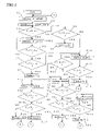
- FIG. 7 is the flow chart of the controller is shown in the drawing to be worked for the generator shown in FIG. 4 .
- FIG. 8 is the flow chart of the controller is shown in the drawing to be worked for the generator shown in FIG. 5 .
- FIG. 9 is the flow chart of the controller is shown in the drawing to be worked for the generator shown in FIG. 6 .
- FIG. 10 is the experimental data which is shown in the graphic representations showing driving torque and speed (rpm), when the generator with the coil having a large number of windings and the coil having a small number of windings is used for hybrid motor.
- a generator controlled voltage by winding coil combined with control coil and power coil in accordance with the present invention will be hereinafter described with reference to the accompany drawings.
- the permanent magnet generator controlled voltage by winding coils as shown in FIG. 1 is comprised of stator hosing 34 which is a pair of housing halved housing 3 and 5 , a rotor shaft 1 supported for rotation in the housing 3 and 5 by means of a pear of axially opposite ball bearings 4 , a rotor 35 of a multi-polar permanent magnet member 7 in which more than one platy permanent magnet pieces is arranged circumferentially around the rotor shaft 1 , a stator 2 arranged around the outer periphery of the rotor 35 .
- the stator 2 is composed by stator core 36 and rolled up by electromagnetic coils 8 arranged in stator core 36 .
- the rotor shaft 1 is composed of a magnetic permeable member 37 arranged on the rotor shaft 1 and the permanent magnet member 7 of more than one permanent magnet piece extended axially. Furthermore, around the outside periphery of the permanent magnet member 7 there is provided a first reinforcing member 40 to keep the permanent magnet member 7 against falling off the rotor 35 owing to a high centrifugal force, the reinforcing member 40 being made of high tensile fibers made of resin.
- the rotor 35 is clamped between axially opposite backing plate 38 and flange and fixed by nut such as tightening tools in integration.
- rectifier 15 is installed in the rear housing 5 , and a solenoid coil 14 is set up in outer side of the front housing 3 .
- the stator coils 8 are wound in the slot of the stator core 36 which are embedded between the teeth of combs and nonmagnetic materials such as resin is inserted in gap of the slot to be fixed the stator coils 8 .
- Stator coil 8 for example, are wound in the slot of stator core 36 and the power coils 10 and control coil 11 are connected with the control switch 12 and solenoid coil 14 in series which is one of example of currying out the present invention and the coil line are connected with three-phase such as star-connection which is also connected with a neutral point 39 as starting point.
- the power switch 13 is connected with the terminal which a wire 41 connects, rectifier 15 , and load 17 in series. Three terminals which the wire 41 connects to each are connected with the rectifier 15 with three-phase and DC electric power produced in the rectifier 15 is sent to the load 17 for single-phase.
- a sensor of voltage and load 16 is located with the load 17 in parallel and the sensor for speed and position of pole produced by permanent magnet members 7 is arranged on the near of the rotor 35 .
- the signals sent from the sensor of voltage and load 16 and the speed and position sensor 28 is inputted to the controller 18 then the controller 18 sends open and close signals to the control switches 12 and power switches 13 to control the voltage constantly.
- the control switch 12 is installed between the power coil 10 and the control coil 11 because of the improving the resistance of high voltage, however it is possible to install it between the control coil 11 and solenoid coil 14 .
- the power coil 10 may be constituted by connecting two or more winding coil in parallel, then the power coil 10 of this parallel connection and the control coil 11 may be connected in series. In this case, it has the advantage that each winding coil which is connected in parallel and used as the power coil 10 can be made small.
- the solenoid coil 14 is connected with the control coil 11 in series, because the solenoid coil 14 makes the current of flowing into control coil 11 reduce dramatically due to large inductance of the solenoid coil 14 when the load 17 and the rotor 35 speed are changed quickly.
- control switches 12 are arranged on the coils between power coil 10 and control coil 11 , because receiving the spike with high voltage is brought the breakage of control switches 12 then arranging the control switch 12 on the coils between the power coil 10 and the control coil 11 is very important because the voltage of the control switch 12 do not increase on this position. Then it is need to arrange the solenoid coils 14 in a position which is no inter-linkage with the magnetic force of the rotor 35 . Then the solenoid coil 14 is put in the out side of housing 34 as showing in FIG. 1 . In order to stabilize the voltage of power coil terminal, condenser is inserted sometimes between the terminals. Then it is better that the end of control coils 11 are connected with solenoid coils 14 and another end of solenoid coils are connected with each other for natural point.
- the controller 18 makes the control switch 12 increase and decrease the periods of closing time to control the current to maintain the voltage constantly when the current generated in the power coil 10 flow into the control coil 11 , the voltage of power coil 10 is controlled without any other complicated controller. If the solenoid coil is eliminated from the circuit, the voltage of the coils reduced 0 volt in case of closing the control switch 12 because the current flow A1 ampere into the control coil 11 as shown in FIG. 2 . However, the current flowing into the control coil 11 is reduced to A2 ampere in case of arranging solenoid coil 14 having large inductance value, as the result, the amplitude of voltage reduce and the voltage of power coil 10 become stable condition even if the control switch 12 is opened and shut in high frequency.
- the controller of generator for generating two kinds of power with different voltages is explained by using FIG. 4 .
- the generator of this aspect has a plurality of terminals which voltage differs and wire 41 L or 41 H connects to each so that it may correspond to the load with low voltage 17 L and the load with high voltage 23 .
- the power coil 10 is composed two kinds of winding coils 19 H and 19 L.
- the power coil for lower voltage 19 L is connected with terminal 27 , switch 20 L, wire 41 L, rectifier 15 and load 17 L in series and the sensor of voltage and load 16 and a storage battery 24 are arranged in the load 17 L in parallel.
- the power coil for higher voltage 19 H is connected with terminal 26 , switch 20 H, wire 41 H, rectifier 21 , and load 23 in series and the sensor of voltage 22 and storage battery 25 are arranged in load 23 in parallel.
- the power coil for lower voltage 19 L is for automotive power source with 12V and the power coil for higher voltage 19 H is for the equipment to drive electric machines such as motor for compressor driven by 100V or 200V.
- the control coil 11 and control switch 12 is connected with the power coil for higher voltage 19 H in series.
- the ratio of winding number in the power coil for lower voltage 19 L, the power coil for higher voltage 19 H and the control coil 11 is decided as following ratio of 12:100:400, the ratio of voltage in the each terminals appeared in the ratio of 12:100:400 V, then we can get 12V in the power terminal for lower voltage 27 and 100 v in the terminal for higher voltage 26 in case of controlling the voltage of 400V in the end of the control coil 11 even if the load is changed in what kind of conditions.
- power coils arranged in a stator to get two kind of voltage however they could not obtain the stable different voltage because the voltage of another power side reduced by effecting from the power side supplied large electric power.
- the control switch 12 is arranged in the coil between the power coil for higher voltage 19 H and control coil 11 and the control coil 11 is connected with solenoid coil 14 .
- This arrangement is very important in the invention.
- the voltage of control coil 11 in the solenoid coil 14 side is increased above 400V because the winding number of control coil 11 is very large. If the control switch 12 is inserted in the coil end between control coil 11 and solenoid coil 14 , the voltage in the control switch 12 increase 1000V when the switch is opened and the current flowing to control coil 11 reduce to 0 ampere. However, the voltage of the control switch 12 remain 100V when the control switch 12 is inserted in the coil 26 between the control coil 11 and the power coil 19 and the solenoid coil 14 having large resistance connected with the control coil 11 in series.
- the large spike of voltage dose not appear in case of making the control switch 12 open and close when the control switch 12 and the solenoid coil 14 are arranged in the position 26 as mentioned above. It is very important technology and feature that the voltage in control switch 12 is maintained in low level because the contact point of control switch 12 is received damage by the spike of high voltage.
- the controller 18 makes the control switch 12 arranged in the coil having large inductance work for chopper which has the function of duty-controlling in order to keep constant voltage by the signal from the sensor of voltage and load 16 , the electric power such as the teeth of a comb is changed to the smooth electric power curve.
- the Control switch 12 is arranged between the power coil 19 and control coil 11 in this example for currying out the invention. In this case, we can use the control switch 12 for low resistance of voltage. However it is possible to arrange the control switch 12 between the control coil 11 and solenoid coil 14 .
- the voltage is reduced in one side of power sources when the power is increased much more in the another side of power sources. Then it is decided priority power source and controller 18 supply the power to the priority power side and cut sending the power to the another side of power source.
- the storage battery 24 and 25 are very important part for storage to supply electric power into the loads 17 L and 23 .
- the generator has two power sources for example 14V and 100V, which are generated in one generator, therefore, the generator has two rectifiers 15 , 21 and two loads 17 , 23 in the circuit.
- the power coil for lower voltage is 19 L and the power coil for higher voltage is 19 H in the power coil 19 .
- the power coil for lower voltage 19 L is connected with switch 20 L, rectifier 15 and load 17 in series and the power coil for higher voltage 19 H is connected with switch 20 H, rectifier 21 and load 23 in series.
- the sensor of voltage and load 16 and 22 are connected with the load 17 and 23 in parallel each together in order to compare the power voltage with the voltage set in advance.
- the power coils 19 L and 19 H are decided the winding number of coils so as to produce 14V and 100V then the controlling one side of voltage constantly is same as controlling another side voltage constantly.
- the controller 18 check the voltage in the power coil for lower voltage 19 L and the power coil for higher voltage 19 H (step S 1 ), and switch on the power switch 20 L and power switch 20 H (step S 2 ), after that the voltage in the power coil VL which is main power is compared with high level voltage (V 1 + ⁇ ) which is higher level of the designated voltage in the allowance (step S 3 ).
- step S 4 When voltage in the power coil VL is higher than (V 1 + ⁇ ) which is higher level of the designated voltage in the allowance, the controller 18 makes the control switch 12 flow the current into the control coil 11 (step S 4 ), as the result, voltage of power coil for lower voltage 19 L reduce because of the down character of voltage in increased current flowing into the control coil 11 .
- step S 5 When voltage in the power coil VL value is lower than (V 1 + ⁇ ) which is higher level of the designated voltage in the allowance
- step S 6 controller 18 maintain the condition for very little time (step S 7 ).
- controller 18 when the controller 18 senses that voltage VL in the power coil for lower voltage 19 L is lower than (V 1 + ⁇ ) which is higher level of the designated voltage in the allowance in step S 3 , controller 18 forward next work of step S 8 .
- the controller 18 investigates if voltage in the power coil VL is larger than (V 1 ⁇ ) which is lower level of the designated voltage in the allowance, and voltage in the power coil VL is smaller than (V 1 ⁇ ) which is lower level of the designated voltage in the allowance, when voltage in the power coil VL is larger, (step S 8 ) controller 18 leave the condition intact, (step S 9 ) when voltage in the power coil VL is smaller, the controller 18 makes the control switch 12 flow the current into the control coil 11 (step S 10 ) and controller admit the voltage in the allowance.
- controller 18 check the voltage if voltage in the power coil VL is larger than (V 1 ⁇ ) which is lower level of the designated voltage in the allowance, (step S 11 ), then controller 18 leave the condition intact (step S 12 ) in case of that voltage in the power coil VL is larger than (V 1 ⁇ ) which is lower level of the designated voltage in the allowance.
- step S 12 When voltage in the power coil VL is smaller than (V 1 ⁇ ) which is lower level of the designated voltage in the allowance, current of control is checked and the current is reduced by controller in case of that the current is larger than 0 (step S 13 ).
- step S 14 When the current reduced to 0 ampere, the switch 20 H is opened to increase the voltage of main power (step S 14 ) then the controller check if voltage in the power coil VL is smaller than (V 1 + ⁇ ) which is higher level of the designated voltage in the allowance (step S 15 ). In case of opening the switch 20 H, electric power is supplied from the storage battery 25 to the higher voltage side 20 H.
- step S 16 When voltage in the power coil VL is smaller than (V 1 + ⁇ ) which is higher level of the designated voltage in the allowance, the controller 18 check if the voltage is larger than (V 1 ⁇ ) which is higher level of the designated voltage in the allowance, (step S 16 ) if so, leave the condition intact (step S 17 ).
- step S 18 the controller sends the trouble signal for user (step S 18 ).
- controller reduce the current I in order to increase the voltage (step S 19 ).
- step S 20 and S 21 the controller 18 investigates if the voltage is kept in the allowance (steps S 20 and S 21 ), after that when voltage in the power coil VL is smaller than (V 1 ⁇ ) which is lower level of the designated voltage in the allowance, controller reduce the current I till voltage VL put in the allowance (V 1 ⁇ ) (steps S 23 and S 24 ).
- step S 22 and S 25 Controller 18 repeat those actions mentioned above.
- a generator controlled voltage by winding coil in accordance with the other example of the present invention will be hereinafter described with reference to the drawing FIG. 5 and FIG. 8 .
- the voltage of power coils 19 L and 19 H are different because of different winding number, those coils 19 L and 19 H can be used for getting same voltage.
- the generator has two kinds of winding coils, a rectifier and load having one kind of voltage in the circuit of the generator to increase the voltage at low speed condition.
- the power coil 19 connected with the power coil for lower voltage 19 L, the power coil for higher voltage 19 H, control switch 12 , control coil 11 and solenoid coil 14 in series. Furthermore, the power coil for lower voltage 19 L is connected with power switch 20 L, the rectifier 15 and the load 17 in series and the power switch 20 H is connected with power switch 20 L between the power coil for higher voltage 19 H and lead wire 41 in parallel.
- the sensor of voltage and load 16 is connected with load 17 in parallel and the controller 18 , control switch 12 , power switch 20 L, and power switch 20 H according to the signal of the sensor of voltage and load 16 and speed and position sensor 28 .
- circuit The purpose of circuit is that power voltage is too low in the low generator speed then the coil having large winding number 19 H is used at low speed condition and the coil having small winding number 19 L is used for above medium speed condition in order to get high power at low speeds.
- the designated voltage for example 12V is checked in the sensor of voltage and load 16 and controller 18 control the voltage by adjusting the current flowing into the control coil 11 , the controller 18 can get the designated voltage in case of producing higher voltage than 12V, however it can not generate the power having 12V in the generator in case of that electric power in the power coil for lower voltage 19 L is not over 12V.
- the circuit is very useful to get high power in the extremely low speed and to get high power in the high speed.
- the controller 18 detects the speed of generator and the generated voltage (step S 30 ) after starter switch is operated and check the speed N of generator if it is lower than designated speed N 1 which is decided before (step S 31 ).
- step S 30 the speed of generator and the generated voltage
- step S 31 the speed of generator if it is lower than designated speed N 1 which is decided before
- step S 31 the power switch 20 L is opened and the power switch 20 H is closed (step S 32 ) to use the power coil with larger winding number.
- step S 33 the controller 18 check the load voltage if the voltage put the allowance of voltage which is (V 1 ⁇ ), (step S 33 ) when the voltage V is larger than (V 1 + ⁇ ) which is higher level of the designated voltage in the allowance, where V 1 is the designated voltage (for example V 1 is 14 V) (steps S 34 and S 36 ) the current of control coil 11 is increased, (step S 35 ,) and when the voltage V is smaller than (V 1 ⁇ ) which is lower level of the designated voltage in the allowance, the controller 18 intact the control switch 12 for 2 ⁇ 3 millisecond and when the voltage V is smaller than lower level of the designated voltage in the allowance (V ⁇ ) (step S 39 ), the controller 18 reduce the current flowing into the control coil 11 (step S 41 ).
- step S 33 the controller 18 checked voltage V if the voltage is contained in the allowance (V 1 ⁇ ) and when voltage V is larger than (V 1 + ⁇ ) which is higher level of the designated voltage in the allowance, the controller makes the current flowing into control coil 11 increase by using the control switch 12 (step S 36 ) furthermore, when voltage V is smaller than (V 1 ⁇ ) which is lower level of the designated voltage in the allowance, the controller 18 reduce the current flowing into control coil 11 by chopping method in the control switch 12 (steps S 37 , S 39 , S 41 and S 42 ). In case of that the voltage V is contained in the allowance V 1 ⁇ , the controller 18 leave the control switch 12 intact for 2 ⁇ 3 millisecond. (steps S 38 and S 40 , step S 43 ), and the controller return the control flow to start position A.
- a generator controlled voltage by winding coil in accordance with the other example of the present invention will be hereinafter described with reference to the drawing FIG. 6 and FIG. 9 .
- the generator is used for starter for example it is used in a hybrid vehicle.
- the pole of electromagnetic In order to work the generator for a starter motor, the pole of electromagnetic must be produced in the stator corresponding to the pole of permanent magnet member 7 .
- the controller 18 perceives the position of permanent magnet member 7 and makes the switch 32 and 33 flow a current from buttery 30 . It is very important to flow current into the power coils 19 H and 19 L on the optimum timing and commutator is used in the starter system generally.
- the generator side controller 18 makes the power switch for higher voltage 20 H connected with the power coil for higher voltage 19 H having a large number of windings flow current in order to work the generator for starter and makes the power switch for lower voltage 20 L connected with the power coil for lower voltage 19 L having a small number of windings flow current to assist driving motor for vehicle which is used a internal combustion engine.
- the circuit of the starter-generator system is shown in FIG. 6 .
- a switch 33 is connected with the power coil for higher voltage 19 H having large winding number, connecting line 42 H and battery 30 in series, and a switch 32 is connected with the power coil for lower voltage 19 L having small winding number, connecting line 42 L and battery 30 in series.
- the circuit of generator system is included in the starter-generator system as shown in FIG. 6 .
- the generator side controller 18 When the generator side controller 18 receives the signal of starter, the controller 18 must judge on the system condition if the generator must be operated for starter or generator. As large torque is required to drive the generator for starter, the generator side controller 18 select the power coil for higher voltage 19 H having a large number of windings to flow the current, however driving torque reduce as speed of motor increase quickly because of producing the reverse electromotive force in the power coil.
- the generator side controller 18 changes the flowing line of current from connecting line 42 H to 42 L.
- the generator side controller 18 switch off the power switch 20 L, 20 H, and generator side control switch 12 and the controller 18 switch on the electric motor side switch 33 and switch off the electric motor side switch 32 in high speed condition.
- the generator is used for assistant motor because the generator maintain driving torque at high speed due to small reverse electromotive force in the power coil for lower voltage having small winding number.
- the switch of generator 20 H and 20 L and the generator side control switch 12 are switch off then the generator side controller 18 makes the electric motor side switches 32 and 33 operate suiting user requirement.
- FIG. 6 one example which the power coils connected in series are used by changing suitable for the requirement of user is explained in FIG. 6 , however it is possible to use the generator for a motor which has single power coil, the electric motor side controller 29 , storage battery 30 , and switch 32 as shown in FIG. 3 .
- the controller judge the generator operation if it is worked for generator or motor (step S 50 ). If the controller is judged it for motor condition, the controller 18 is switched off the power switches 20 H and 20 L, and the generator side control switch 12 , because those switches are worked for generator (step S 51 ).
- the generator side controller 18 check the speed of generator (step S 52 ) and when generator speed N is smaller than N 1 , the controller switch on the switch 33 and switch off the switch 32 , because the generator is used for starter (step S 53 ). If the speed of generator N is larger than N 1 , the controller 18 switch on the switch 32 and switch off the switch 33 , because the generator is used for driving assist on a hybrid vehicle (step S 54 ).
- the position of flowing current into power coil 19 is decided automatically by the signal of sensor 28 .
- the controller 18 send the signal to open and close to the switch 32 and 33 then the current of flowing into the power coil 19 produce the electromagnetic force automatically in order to drive the motor.
- the controller 18 inputted the program of current flowing such as a sine curve, make the switch flow the current, the motor efficiency is improved much more.
- the controller 18 makes the system work for the generator (step S 55 ).
- the generator is used for motor, which coil is winded by 20 turns and 40 turns, the experiment was carried out. The data is shown in FIG. 10 . We can understand that large torque was get in large winding number coil, and driving torque was extended to high speed condition in the coil with small winding number.
- the generator and control system in accordance with the present invention is very effective to improve the vehicle efficiency.
- the system is used for vehicle, industrial generator, wind turbine and electric car, we can get constant voltage, high power and high efficiency in spite of small size, light weight and cheap cost.
Priority Applications (3)
| Application Number | Priority Date | Filing Date | Title |
|---|---|---|---|
| KR1020080137039A KR20090119674A (ko) | 2008-05-15 | 2008-12-30 | 영구 자석식 발전기의 제어 장치 |
| EP09158587A EP2120325A2 (en) | 2008-05-15 | 2009-04-23 | Controller of permanent magnet generator |
| CN2009101414234A CN101582672B (zh) | 2008-05-15 | 2009-05-13 | 永磁式发电机的控制装置 |
Applications Claiming Priority (1)
| Application Number | Priority Date | Filing Date | Title |
|---|---|---|---|
| JP2008127862 | 2008-05-15 |
Publications (1)
| Publication Number | Publication Date |
|---|---|
| US7554303B1 true US7554303B1 (en) | 2009-06-30 |
Family
ID=40445104
Family Applications (1)
| Application Number | Title | Priority Date | Filing Date |
|---|---|---|---|
| US12/192,384 Expired - Fee Related US7554303B1 (en) | 2008-05-15 | 2008-08-15 | Controller of permanent magnet generator |
Country Status (5)
| Country | Link |
|---|---|
| US (1) | US7554303B1 (ja) |
| EP (1) | EP2120325A2 (ja) |
| JP (1) | JP4227189B1 (ja) |
| KR (1) | KR20090119674A (ja) |
| CN (2) | CN101582674A (ja) |
Cited By (22)
| Publication number | Priority date | Publication date | Assignee | Title |
|---|---|---|---|---|
| US20110074366A1 (en) * | 2009-09-29 | 2011-03-31 | Himmelmann Richard A | Permanent magnet generator having passive flux control |
| US20110140432A1 (en) * | 2008-05-23 | 2011-06-16 | Acedo Sanchez Jorge | Control method and system for a wind power installation in case of grid faults |
| WO2011028959A3 (en) * | 2009-09-03 | 2011-07-14 | Exro Technologies Inc. | Variable coil configuration system, apparatus and method |
| US20110185206A1 (en) * | 2008-08-22 | 2011-07-28 | Drs Power & Control Technologies, Inc. | Multiple voltage generator and voltage regulation methodology for power dense integrated power systems |
| US20110254285A1 (en) * | 2010-04-15 | 2011-10-20 | Hanchett Entry Systems, Inc. | Electromagnetic Energy Harvester and a Door Latch Release Mechanism as an Energy Source for the Harvester |
| US20130113442A1 (en) * | 2010-07-12 | 2013-05-09 | Masayo Kawamura | Controller and systems of permanent magnet alternator and motor |
| US20140035529A1 (en) * | 2011-10-12 | 2014-02-06 | Mechanical Energy Generating Systems, L.L.C. | Systems, Methods, and Apparatus for a Homopolar Generator Charger with Integral Rechargeable Battery |
| WO2014150135A1 (en) * | 2013-03-15 | 2014-09-25 | Remy Technologies, L.L.C. | Vehicle system with batteries in series |
| US8941961B2 (en) | 2013-03-14 | 2015-01-27 | Boulder Wind Power, Inc. | Methods and apparatus for protection in a multi-phase machine |
| US9379552B2 (en) | 2008-09-03 | 2016-06-28 | Exro Technologies Inc. | Power conversion system for a multi-stage generator |
| US9548612B2 (en) | 2012-09-28 | 2017-01-17 | Kohler Co. | Paralleling module for a generator system |
| US20170207738A1 (en) * | 2014-07-25 | 2017-07-20 | Robert Bosch Gmbh | Electric machine for the power supply of a motor vehicle electrical system |
| US9871378B2 (en) | 2012-09-28 | 2018-01-16 | Kohler Co. | Paralleling module for a generator system |
| CN109525098A (zh) * | 2019-01-25 | 2019-03-26 | 重庆交通职业学院 | 汽车自调节永磁发电机 |
| WO2019150320A1 (de) * | 2018-02-03 | 2019-08-08 | Engit Research Gmbh | Generator und verfahren zur erzeugung von elektrischem strom |
| US10411620B2 (en) * | 2015-07-31 | 2019-09-10 | Koki Holdings Co., Ltd. | Power tool |
| US10514011B2 (en) | 2016-10-04 | 2019-12-24 | Shindengen Electric Manufacturing Co., Ltd. | Starting power generation apparatus and starting power generation method |
| US10753335B2 (en) | 2018-03-22 | 2020-08-25 | Continental Motors, Inc. | Engine ignition timing and power supply system |
| US11081996B2 (en) | 2017-05-23 | 2021-08-03 | Dpm Technologies Inc. | Variable coil configuration system control, apparatus and method |
| US11708005B2 (en) | 2021-05-04 | 2023-07-25 | Exro Technologies Inc. | Systems and methods for individual control of a plurality of battery cells |
| US11722026B2 (en) | 2019-04-23 | 2023-08-08 | Dpm Technologies Inc. | Fault tolerant rotating electric machine |
| US11967913B2 (en) | 2022-05-12 | 2024-04-23 | Exro Technologies Inc. | Method and apparatus to drive coils of a multiphase electric machine |
Families Citing this family (6)
| Publication number | Priority date | Publication date | Assignee | Title |
|---|---|---|---|---|
| KR101128515B1 (ko) * | 2010-04-22 | 2012-03-27 | 주식회사 져스텍 | 출력 전압을 조절하는 발전 장치 |
| CN102447438A (zh) * | 2010-10-08 | 2012-05-09 | 河南森源电气股份有限公司 | 永磁风力发电机线圈连接的切换装置 |
| WO2012120693A1 (en) * | 2011-03-09 | 2012-09-13 | Kawamura, Megumi | Controller of permanent magnet generator and permanent magnet generator with the controller |
| CN107070105A (zh) * | 2017-04-18 | 2017-08-18 | 深圳市瑞迪构科技有限公司 | 一种程控发电机 |
| US11482360B2 (en) | 2017-12-12 | 2022-10-25 | The Boeing Company | Stator secondary windings to modify a permanent magnet (PM) field |
| CN112332724B (zh) * | 2020-11-13 | 2022-02-11 | 中国科学院电工研究所 | 发电机、发电系统及发电机控制方法 |
Citations (4)
| Publication number | Priority date | Publication date | Assignee | Title |
|---|---|---|---|---|
| US6034511A (en) | 1994-09-14 | 2000-03-07 | Coleman Powermate, Inc. | Light weight rotor and stator with multiple coil windings in thermal contact |
| US6541887B2 (en) | 1999-03-12 | 2003-04-01 | Hideo Kawamura | Permanent-magnet motor-generator with voltage stabilizer |
| US7388300B2 (en) * | 2006-09-20 | 2008-06-17 | Honeywell International, Inc. | Starter-generator operable with multiple variable frequencies and voltages |
| US7501799B2 (en) * | 2007-06-20 | 2009-03-10 | Hamilton Sundstrand Corporation | Engine start system with a regulated permanent magnet machine |
Family Cites Families (5)
| Publication number | Priority date | Publication date | Assignee | Title |
|---|---|---|---|---|
| JP2003245000A (ja) | 2002-02-20 | 2003-08-29 | Matsushita Electric Ind Co Ltd | 発電機および発電装置 |
| JP2004320972A (ja) | 2003-03-28 | 2004-11-11 | Matsushita Electric Ind Co Ltd | 永久磁石回転電機、永久磁石回転電機の制御方法、車両、風力発電機システム、及びエンジン発電機 |
| US6965183B2 (en) | 2003-05-27 | 2005-11-15 | Pratt & Whitney Canada Corp. | Architecture for electric machine |
| JP2006345592A (ja) * | 2005-06-07 | 2006-12-21 | Fuji Seratekku Kk | 極低速で回転する高出力発電機 |
| CN100426656C (zh) * | 2006-01-25 | 2008-10-15 | 包头长安永磁电机研发有限公司 | 永磁直流无刷变速恒压风力发电机及其稳压方法 |
-
2008
- 2008-08-15 US US12/192,384 patent/US7554303B1/en not_active Expired - Fee Related
- 2008-09-16 JP JP2008236363A patent/JP4227189B1/ja not_active Expired - Fee Related
- 2008-12-25 CN CNA200810190319XA patent/CN101582674A/zh active Pending
- 2008-12-30 KR KR1020080137039A patent/KR20090119674A/ko not_active Application Discontinuation
-
2009
- 2009-04-23 EP EP09158587A patent/EP2120325A2/en not_active Withdrawn
- 2009-05-13 CN CN2009101414234A patent/CN101582672B/zh not_active Expired - Fee Related
Patent Citations (4)
| Publication number | Priority date | Publication date | Assignee | Title |
|---|---|---|---|---|
| US6034511A (en) | 1994-09-14 | 2000-03-07 | Coleman Powermate, Inc. | Light weight rotor and stator with multiple coil windings in thermal contact |
| US6541887B2 (en) | 1999-03-12 | 2003-04-01 | Hideo Kawamura | Permanent-magnet motor-generator with voltage stabilizer |
| US7388300B2 (en) * | 2006-09-20 | 2008-06-17 | Honeywell International, Inc. | Starter-generator operable with multiple variable frequencies and voltages |
| US7501799B2 (en) * | 2007-06-20 | 2009-03-10 | Hamilton Sundstrand Corporation | Engine start system with a regulated permanent magnet machine |
Cited By (36)
| Publication number | Priority date | Publication date | Assignee | Title |
|---|---|---|---|---|
| US20110140432A1 (en) * | 2008-05-23 | 2011-06-16 | Acedo Sanchez Jorge | Control method and system for a wind power installation in case of grid faults |
| US8541898B2 (en) * | 2008-05-23 | 2013-09-24 | Ingeteam Power Technology, S.A. | Control method and system for a wind power installation in case of grid faults |
| US8928292B2 (en) * | 2008-08-22 | 2015-01-06 | Drs Power & Control Technologies, Inc. | Multiple voltage generator and voltage regulation methodology for power dense integrated power systems |
| US20110185206A1 (en) * | 2008-08-22 | 2011-07-28 | Drs Power & Control Technologies, Inc. | Multiple voltage generator and voltage regulation methodology for power dense integrated power systems |
| US9075593B2 (en) | 2008-08-22 | 2015-07-07 | Drs Power & Control Technologies, Inc. | Multiple voltage generator and voltage regulation methodology for power dense integrated power systems |
| US9379552B2 (en) | 2008-09-03 | 2016-06-28 | Exro Technologies Inc. | Power conversion system for a multi-stage generator |
| WO2011028959A3 (en) * | 2009-09-03 | 2011-07-14 | Exro Technologies Inc. | Variable coil configuration system, apparatus and method |
| US9812981B2 (en) | 2009-09-03 | 2017-11-07 | Exro Technologies Inc. | Variable coil configuration system, apparatus and method |
| US8193783B2 (en) | 2009-09-29 | 2012-06-05 | Hamilton Sundstrand Corporation | Permanent magnet generator having passive flux control |
| US20110074366A1 (en) * | 2009-09-29 | 2011-03-31 | Himmelmann Richard A | Permanent magnet generator having passive flux control |
| US8659176B2 (en) * | 2010-04-15 | 2014-02-25 | Hanchett Entry Systems, Inc. | Electromagnetic energy harvester and a door latch release mechanism as an energy source for the harvester |
| US20110254285A1 (en) * | 2010-04-15 | 2011-10-20 | Hanchett Entry Systems, Inc. | Electromagnetic Energy Harvester and a Door Latch Release Mechanism as an Energy Source for the Harvester |
| US8823333B2 (en) * | 2010-07-12 | 2014-09-02 | Hideo Kawamura | Controller and systems of permanent magnet alternator and motor |
| US20130113442A1 (en) * | 2010-07-12 | 2013-05-09 | Masayo Kawamura | Controller and systems of permanent magnet alternator and motor |
| US9893597B2 (en) | 2011-10-12 | 2018-02-13 | Premergy, Inc. | Systems, methods, and apparatus for a homopolar generator charger with integral rechargeable battery |
| US20140035529A1 (en) * | 2011-10-12 | 2014-02-06 | Mechanical Energy Generating Systems, L.L.C. | Systems, Methods, and Apparatus for a Homopolar Generator Charger with Integral Rechargeable Battery |
| US9073440B2 (en) * | 2011-10-12 | 2015-07-07 | Mechanical Energy Generating Systems, L.L.C. | Systems, methods, and apparatus for a homopolar generator charger with integral rechargeable battery |
| US9548612B2 (en) | 2012-09-28 | 2017-01-17 | Kohler Co. | Paralleling module for a generator system |
| US9871378B2 (en) | 2012-09-28 | 2018-01-16 | Kohler Co. | Paralleling module for a generator system |
| US8941961B2 (en) | 2013-03-14 | 2015-01-27 | Boulder Wind Power, Inc. | Methods and apparatus for protection in a multi-phase machine |
| US9555712B2 (en) | 2013-03-15 | 2017-01-31 | Remy Technologies, L.L.C. | Vehicle system with batteries in series |
| WO2014150135A1 (en) * | 2013-03-15 | 2014-09-25 | Remy Technologies, L.L.C. | Vehicle system with batteries in series |
| US20170207738A1 (en) * | 2014-07-25 | 2017-07-20 | Robert Bosch Gmbh | Electric machine for the power supply of a motor vehicle electrical system |
| US10411620B2 (en) * | 2015-07-31 | 2019-09-10 | Koki Holdings Co., Ltd. | Power tool |
| US10514011B2 (en) | 2016-10-04 | 2019-12-24 | Shindengen Electric Manufacturing Co., Ltd. | Starting power generation apparatus and starting power generation method |
| US11081996B2 (en) | 2017-05-23 | 2021-08-03 | Dpm Technologies Inc. | Variable coil configuration system control, apparatus and method |
| WO2019150320A1 (de) * | 2018-02-03 | 2019-08-08 | Engit Research Gmbh | Generator und verfahren zur erzeugung von elektrischem strom |
| US10753335B2 (en) | 2018-03-22 | 2020-08-25 | Continental Motors, Inc. | Engine ignition timing and power supply system |
| US10920738B2 (en) | 2018-03-22 | 2021-02-16 | Continental Motors, Inc. | Engine ignition timing and power supply system |
| US10920736B2 (en) | 2018-03-22 | 2021-02-16 | Continental Motors, Inc. | Engine ignition timing and power supply system |
| US10920737B2 (en) | 2018-03-22 | 2021-02-16 | Continental Motors, Inc. | Engine ignition timing and power supply system |
| CN109525098A (zh) * | 2019-01-25 | 2019-03-26 | 重庆交通职业学院 | 汽车自调节永磁发电机 |
| CN109525098B (zh) * | 2019-01-25 | 2024-02-02 | 重庆交通职业学院 | 汽车自调节永磁发电机 |
| US11722026B2 (en) | 2019-04-23 | 2023-08-08 | Dpm Technologies Inc. | Fault tolerant rotating electric machine |
| US11708005B2 (en) | 2021-05-04 | 2023-07-25 | Exro Technologies Inc. | Systems and methods for individual control of a plurality of battery cells |
| US11967913B2 (en) | 2022-05-12 | 2024-04-23 | Exro Technologies Inc. | Method and apparatus to drive coils of a multiphase electric machine |
Also Published As
| Publication number | Publication date |
|---|---|
| CN101582672B (zh) | 2013-03-13 |
| JP4227189B1 (ja) | 2009-02-18 |
| CN101582674A (zh) | 2009-11-18 |
| EP2120325A2 (en) | 2009-11-18 |
| CN101582672A (zh) | 2009-11-18 |
| JP2009303471A (ja) | 2009-12-24 |
| KR20090119674A (ko) | 2009-11-19 |
Similar Documents
| Publication | Publication Date | Title |
|---|---|---|
| US7554303B1 (en) | Controller of permanent magnet generator | |
| US8823333B2 (en) | Controller and systems of permanent magnet alternator and motor | |
| JP4116292B2 (ja) | ハイブリッド車用電動発電システム | |
| US8587229B2 (en) | Method and electrical machine for braking a thermal engine of vehicle during the stop phase thereof | |
| US8245802B2 (en) | Automotive hybrid engine assist system | |
| CN102470812B (zh) | 车辆用电源系统 | |
| US8148866B2 (en) | Regulated hybrid permanent magnet generator | |
| US7135784B2 (en) | Fast torque control of a belted alternator starter | |
| KR20060063767A (ko) | 가역 회전식 전기기기용 제어장치 | |
| US20190173404A1 (en) | Control of hybrid permanent magnet machine with rotating power converter and energy source | |
| EP1501169A2 (en) | Hybrid electrical machine with system and method for controlling such hybrid machine | |
| CN113162354A (zh) | 一种宽转速范围无刷电励磁同步发电机 | |
| KR101322514B1 (ko) | 영구 자석 발전기의 제어기 및 제어기를 구비한 영구 자석 발전기 | |
| JP5638465B2 (ja) | 車両用電源システム | |
| US6703808B1 (en) | Active power limiting for starter/alternator in the generation mode | |
| JP2017017954A (ja) | 船外機用発電システムおよび船外機 | |
| JP4463872B1 (ja) | 永久磁石式発電機の制御装置 | |
| JP2003284378A (ja) | 車両用交流発電電動装置 | |
| JP2003102153A (ja) | 車両用交流発電電動装置 | |
| KR20130136823A (ko) | 모터 및 모터 시스템 |
Legal Events
| Date | Code | Title | Description |
|---|---|---|---|
| AS | Assignment |
Owner name: KAWAMURA, MEGUMI, JAPAN Free format text: ASSIGNMENT OF ASSIGNORS INTEREST;ASSIGNOR:KAWAMURA, HIDEO;REEL/FRAME:021418/0529 Effective date: 20080617 Owner name: KAWAMURA, HIDEO, JAPAN Free format text: ASSIGNMENT OF ASSIGNORS INTEREST;ASSIGNOR:KAWAMURA, HIDEO;REEL/FRAME:021418/0529 Effective date: 20080617 |
|
| REMI | Maintenance fee reminder mailed | ||
| LAPS | Lapse for failure to pay maintenance fees | ||
| STCH | Information on status: patent discontinuation |
Free format text: PATENT EXPIRED DUE TO NONPAYMENT OF MAINTENANCE FEES UNDER 37 CFR 1.362 |
|
| FP | Lapsed due to failure to pay maintenance fee |
Effective date: 20130630 |