US7554068B2 - Heat radiating structure for solid-state image sensor, and solid-state image pickup device - Google Patents
Heat radiating structure for solid-state image sensor, and solid-state image pickup device Download PDFInfo
- Publication number
- US7554068B2 US7554068B2 US12/028,109 US2810908A US7554068B2 US 7554068 B2 US7554068 B2 US 7554068B2 US 2810908 A US2810908 A US 2810908A US 7554068 B2 US7554068 B2 US 7554068B2
- Authority
- US
- United States
- Prior art keywords
- heat radiating
- solid
- state image
- contact
- heat
- Prior art date
- Legal status (The legal status is an assumption and is not a legal conclusion. Google has not performed a legal analysis and makes no representation as to the accuracy of the status listed.)
- Expired - Fee Related, expires
Links
Images


Classifications
-
- H—ELECTRICITY
- H04—ELECTRIC COMMUNICATION TECHNIQUE
- H04N—PICTORIAL COMMUNICATION, e.g. TELEVISION
- H04N23/00—Cameras or camera modules comprising electronic image sensors; Control thereof
- H04N23/50—Constructional details
- H04N23/54—Mounting of pick-up tubes, electronic image sensors, deviation or focusing coils
-
- H—ELECTRICITY
- H04—ELECTRIC COMMUNICATION TECHNIQUE
- H04N—PICTORIAL COMMUNICATION, e.g. TELEVISION
- H04N23/00—Cameras or camera modules comprising electronic image sensors; Control thereof
- H04N23/10—Cameras or camera modules comprising electronic image sensors; Control thereof for generating image signals from different wavelengths
- H04N23/13—Cameras or camera modules comprising electronic image sensors; Control thereof for generating image signals from different wavelengths with multiple sensors
- H04N23/16—Optical arrangements associated therewith, e.g. for beam-splitting or for colour correction
-
- F—MECHANICAL ENGINEERING; LIGHTING; HEATING; WEAPONS; BLASTING
- F28—HEAT EXCHANGE IN GENERAL
- F28F—DETAILS OF HEAT-EXCHANGE AND HEAT-TRANSFER APPARATUS, OF GENERAL APPLICATION
- F28F3/00—Plate-like or laminated elements; Assemblies of plate-like or laminated elements
- F28F3/02—Elements or assemblies thereof with means for increasing heat-transfer area, e.g. with fins, with recesses, with corrugations
Definitions
- the present invention relates to a heat radiating structure for solid-state image sensors to be used for image pickup devices such as television cameras and video cameras including solid-state image sensors, as well as to a solid-state image pickup device having such a heat radiating structure.
- 3CCD color cameras (hereinafter, referred to as 3CCD cameras) as an image pickup device using three solid-state image sensors.
- 3CCD cameras 3CCD color cameras
- the structure of such a conventional 3CCD camera is explained below with reference to the accompanying drawings.
- FIG. 1 is a schematic sectional view of an image pickup block 10 in a conventional 3CCD camera.
- the image pickup block 10 includes a color separation prism for separating incident light, which has come up through an unshown image pickup lens of the 3CCD camera, into color components, a plurality of solid-state image sensors, and image sensor boards on which the solid-state image sensors are mounted, respectively.
- the color separation prism is made up of three prism members 1 r , 1 g , 1 b , which are joined together in close contact with one another.
- the color separation prism constructed like this is a three color separation prism 1 for separating incident light into three color components. Junction interfaces among the prism members 1 r , 1 g , 1 b serve as dichroic mirrors 4 , 5 .
- solid-state image sensors 2 r , 2 g , 2 b are fixed individually with adhesive.
- a light beam 7 incident on the three color separation prism 1 is separated by the dichroic mirrors 4 , 5 into three color components, i.e. light beams 6 a , 6 b , 6 c of three primary colors of light, and the resultant light beams are received by their corresponding solid-state image sensors 2 r , 2 g , 2 b , respectively.
- the light beams 6 a , 6 b are totally reflected again within the prism members 1 g , 1 b , respectively, thereby being received by the solid-state image sensors 2 g , 2 b as light beams that form not mirror images (reflected images) but non-mirror images.
- Image pickup signal processing for the individual light beams received by the solid-state image sensors 2 g , 2 b , 2 r , respectively, is performed by the image sensor boards 3 r , 3 g , 3 b , respectively, so that a color television signal into which the image pickup signals have been synthesized is obtained.
- a solid-state image sensor if used under a high-temperature environment, would undergo occurrence of image quality deterioration due to white scratches, life reduction and so on, and therefore needs to be used at a specified temperature or lower.
- the ambient temperature of the solid-state image sensors i.e., internal temperature within the device casing
- Document 1 proposes a heat radiating structure in which a thermoelectric cooling device mounted on a heat transfer member by screws is placed so as to be in contact with the back face of each solid-state image sensor.
- Document 1 says that, in such a heat radiating structure, since deformations due to thermal expansion and thermal contraction of each member can be absorbed by backlashes of the screws, forces due to the thermal deformations can be prevented from being applied from the cooling device to the solid-state image sensors.
- Document 2 proposes a heat radiating structure in which a thermoelectric cooling device fixed to a heat conducting plate is so placed as to be in close contact with the back faces of the solid-state image sensors with proper force by utilizing the elasticity of the heat conducting plate.
- Document 2 says that, in such a heat radiating structure, since the cooling device can be put into close contact with the back faces of the solid-state image sensors by utilizing the elasticity of the heat conducting plate, there can be realized an efficient heat radiation.
- Document 3 proposes a heat radiating structure using no thermoelectric cooling device in which one end of a metallic component is inserted between the back face of a solid-state image sensor and the image sensor board while the other end of the metallic component is fixed to a metal frame so that heat transferred from the solid-state image sensor to the metallic component is released to the metal frame.
- an object of the present invention lying in solving the above-described issues, is to provide a heat radiating structure of solid-state image sensors to be used for a solid-state image pickup device having those solid-state image sensors, the heat radiating structure of solid-state image sensors serving for cooling the solid-state image sensors while reducing any external-force loads applied to the solid-state image sensors with a simple structure, as well as to provide a solid-state image pickup device having such a heat radiating structure.
- the present invention has the following constitutions.
- a heat radiating structure for solid-state image sensors comprising:
- a heat radiating member which has a contact portion to be put into contact with a solid-state image sensor fixed to a prism member, and a fin-like heat radiating portion for radiating heat into surrounding gas, the heat being transferred through the contact portion,
- contact portion and the heat radiating portion are formed from a foil member made of a high heat conductivity material.
- the heat radiating structure for solid-state image sensors as defined in the first aspect, wherein the contact portion of the heat radiating member is put into contact with the solid-state image sensor via a contact aid material.
- the heat radiating structure for solid-state image sensors as defined in the first aspect, wherein in the heat radiating member, the fin-like heat radiating portion is so shaped that the foil member is bent or folded in its thicknesswise direction.
- the heat radiating structure for solid-state image sensors as defined in the first aspect, wherein a plurality of the heat radiating members are in contact with a plurality of the solid-state image sensors, respectively and independently, which are fixed to a plurality of the prism members constituting a color separation prism for separating light into a plurality of color components.
- the heat radiating structure for solid-state image sensors as defined in the fourth aspect, wherein widthwise directions of the heat radiating members in the fin-like heat radiating portions are set along an identical direction among all the heat radiating members.
- the heat radiating structure for solid-state image sensors as defined in the first aspect, wherein the contact portion is placed so as to be in contact with a substantially entire surface of one face of the solid-state image sensor, and the fin-like heat radiating portion is formed from the foil member extending from mutually opposing end portions of the contact portion, respectively.
- the heat radiating member comprises first and second ones of the contact portions which are fixed to a plurality of the prism members, respectively and independently, and which are put into contact with mutually adjoining first and second ones of the solid-state image sensors, respectively and independently, and the heat radiating portion for radiating heat into surrounding gas, the heat being transferred through the first and second contact portions, wherein
- the heat radiating portion is placed between the first and second contact portions
- the respective first and second contact portions and the heat radiating portion are formed by the foil member in continuation, respectively, and
- the heat radiating portion has such a fin-like shape that the foil member is folded or bent a plurality of times.
- the heat radiating structure for solid-state image sensors as defined in the seventh aspect further comprising:
- the respective second and third contact portions and the another heat radiating portion are formed from a single-in-continuation foil member made of a high heat conductivity material.
- the heat radiating structure for solid-state image sensors as defined in the seventh aspect, wherein in the heat radiating portion, a plurality of cutout portions are formed along a direction perpendicular to a widthwise direction of the heat radiating member.
- the heat radiating structure for solid-state image sensors as defined in the ninth aspect, wherein the cutout portions are slits each having a width.
- a solid-state image pickup device comprising:
- a color separation prism made up of a plurality of prism members, for separating light into a plurality of color components
- contact portions and the heat radiating portions are formed from a foil member made of a high heat conductivity material.
- the solid-state image pickup device as defined in the eleventh aspect, wherein widthwise directions of the heat radiating members in the fin-like heat radiating portions are set along an identical direction among all the heat radiating members.
- a solid-state image pickup device comprising:
- a heat radiating member which has a contact portion to be put into contact with the solid-state image sensor, and a fin-like heat radiating portion for radiating heat into its surrounding gas, the heat being transferred through the contact portion,
- contact portion and the heat radiating portion are formed from a foil member made of a high heat conductivity material.
- the solid-state image pickup device as defined in the 13th aspect, wherein the contact portion of the heat radiating member is put into contact with the solid-state image sensor via a contact aid material.
- the solid-state image pickup device as defined in the 13th aspect, wherein in the heat radiating member, the fin-like heat radiating portion is so shaped that the foil member is bent or folded in its thicknesswise direction.
- the solid-state image pickup device as defined in the 13th aspect, wherein the contact portion is placed so as to be in contact with a substantially entire surface of one face of the solid-state image sensor, and the fin-like heat radiating portion is formed from the foil member extending from mutually opposing end portions of the contact portion, respectively.
- the solid-state image pickup device as defined in the 13th aspect, comprising:
- a color separation prism made up of a plurality of the prism members, for separating light into a plurality of color components
- the heat radiating member has first and second ones of the contact portions which are put into contact with mutually adjoining first and second ones out of the plurality of solid-state image sensors, respectively and independently, and the heat radiating portion for radiating
- the heat radiating portion is placed between the first and second contact portions, and the respective first and second contact portions and the heat radiating portion are formed by the foil member in continuation, and
- the heat radiating portion has such a fin-like shape that the foil member is folded or bent a plurality of times.
- the solid-state image pickup device as defined in the 17th aspect, the heat radiating member further comprising:
- the respective second and third contact portions and the another heat radiating portion are formed from a single-in-continuation foil member made of a high heat conductivity material.
- the solid-state image pickup device as defined in the 13th aspect, wherein in the heat radiating portion, a plurality of cutout portions are formed along a direction perpendicular to a widthwise direction of the heat radiating member.
- the solid-state image pickup device as defined in the 19th aspect, wherein the cutout portions are slits each having a width.
- the heat radiating member having a contact portion to be put into contact with solid-state image sensors and a heat radiating portion having a fin-like shape or folded-in-plural-times shape or a bent-in-plural-times shape is not fixed to a casing or other member so that heat is radiated into the surrounding gas through the fin-like or other shaped heat radiating portion. That is, according to the present invention, there is not adopted a structure in which a heat radiating member is fixed to a casing or other member as in conventional heat radiating structures.
- a heat radiating structure for solid-state image sensors capable of suppressing deteriorations of the registration accuracy, as well as a solid-state image pickup device having such a heat radiating structure.
- FIG. 1 is a schematic view of an image pickup block in a conventional 3CCD color camera
- FIG. 2 is a schematic perspective view of an image pickup block which has not yet equipped with a heat radiating structure for solid-state image sensors according to a first embodiment of the invention
- FIG. 3 is a schematic perspective view of the image pickup block of FIG. 2 that is equipped with the heat radiating structure of the first embodiment
- FIG. 4 is a schematic perspective view of a heat radiating member of the first embodiment
- FIG. 5 is a schematic perspective view of an image pickup block equipped with a heat radiating structure according to a modification of the first embodiment
- FIG. 6 is a schematic perspective view of an image pickup block equipped with a heat radiating structure for solid-state image sensors according to a second embodiment of the invention.
- FIG. 7 is a schematic perspective view of a heat radiating member of the second embodiment
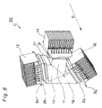
- FIG. 8 is a schematic perspective view of an image pickup block equipped with a heat radiating structure according to a modification of the second embodiment
- FIG. 9 is a schematic perspective view of an image pickup block equipped with a heat radiating structure for solid-state image sensors according to a third embodiment of the invention.
- FIG. 10 is a schematic perspective view of a heat radiating member of the third embodiment.
- FIG. 11 is a schematic perspective view of an image pickup block equipped with a heat radiating structure for solid-state image sensors according to a fourth embodiment of the invention.
- FIG. 12 is a schematic perspective view of a heat radiating member of the fourth embodiment.
- FIG. 2 shows a schematic perspective view of an image pickup block 20 in a 3CCD camera which adopts a heat radiating structure for solid-state image sensors according to a first embodiment of the invention (where the image pickup block 20 is not equipped with a heat radiating structure).
- FIG. 3 shows a schematic perspective view of the image pickup block 20 equipped with the heat radiating structure of the first embodiment. It is noted that the image pickup block 20 is similar in structure itself to the image pickup block 10 of FIG. 1 , and so like component members are designated by like reference numerals and their description is omitted.
- the heat radiating structure for solid-state image sensors of the first embodiment is so made up that fin-like heat radiating members (heat-radiating fin members) 11 , 12 , 13 implemented by foil members formed from high heat conductivity material are separately placed so as to be in contact with back faces of their corresponding solid-state image sensors 2 r , 2 g , 2 b .
- Heat generated in the solid-state image sensors 2 r , 2 g , 2 b is released into their surrounding gas, i.e. atmospheric air, through the individual heat radiating members 11 , 12 , 13 without interposition of any other member.
- temperatures of the individual solid-state image sensors 2 r , 2 g , 2 b can be decreased.
- FIG. 4 shows a schematic perspective view of an external structure of the heat radiating member 11 that typifies the heat radiating members 11 , 12 , 13 having an identical configuration.
- the heat radiating member 11 includes a contact portion 11 a at its bottom portion as viewed in the figure, and a heat radiating portion 11 b at its top portion.
- the contact portion 11 a when in contact with the back face of the solid-state image sensor 2 r (i.e., a face of the solid-state image sensor opposite to its light-receiving face), transfers heat generated in the solid-state image sensor 2 r to the heat radiating member 11 by the contact.
- the heat radiating portion 11 b has a plurality of fins which are accordion-folded-like shaped so as to increase its contact area with the ambient atmosphere, i.e. the heat radiating area, by an arrangement that a foil member extending upward, as viewed in the figure, from mutually opposing end portions in the bottom portion is bent or folded a plurality of times in its thicknesswise direction.
- the contact portion 11 a and the heat radiating portion 11 b are formed by using a foil member having a specified width (e.g., one continued unit of foil member).
- a foil member for example, copper or graphite sheet or the like is used as a high heat conductivity material (a material having a high thermal conductivity), and formed into a foil shape having a thickness of, for example, 0.1 mm or less.
- the contact portion 11 a formed from the foil member is placed between the solid-state image sensor 2 r and the image sensor board 3 r , in which placement the bottom face of the contact portion 11 a is set in contact with the back face of the solid-state image sensor 2 r .
- dimensions (length and width) of the contact portion 11 a are so determined that the contact portion 11 a is brought into contact with a generally entire flat portion of the back face of the solid-state image sensor 2 r in order to ensure enough contact area to allow the heat generated in the solid-state image sensor 2 r to escape effectively.
- the contact between the solid-state image sensor and the heat radiating member includes both cases where the two members are in direct contact without intervention of any other member and where those are in indirect contact with intervention of a contact aid material typified by grease with the aim of improving the contactability between the solid-state image sensor and the heat radiating member.
- the contact portion 11 a of the heat radiating member 11 which is placed between the solid-state image sensor 2 r and the image sensor board 3 r , is lightly sandwiched therebetween so that the heat radiating member 11 is held in its placement position.
- the heat radiating member 11 may be provided slidably movable to some degree of freedom while held contactable with the solid-state image sensor 2 r . That is, as far as the contactability between the solid-state image sensor and the heat radiating member is kept, relative movement of the heat radiating member to the solid-state image sensor does not matter.
- the other heat radiating members 12 , 13 as well are similar in structure to the heat radiating member 11 and so placed as to be in contact with the solid-state image sensors 2 g , 2 b , respectively. Further, in this first embodiment, in the state that the heat radiating members 11 , 12 , 13 are each mounted on the image pickup block 20 as shown above, the heat radiating members 11 , 12 , 13 are so placed as to be kept from contact with any other member such as other heat radiating member, casing, and lens barrel casing.
- the heat radiating structure for solid-state image sensors adopts an arrangement in which the heat radiating members 11 , 12 , 13 are so placed as to be in contact with the back faces of the solid-state image sensors 2 r , 2 g , 2 b , respectively, which are fixed to the prism members 1 r , 1 g , 1 b , respectively, constituting the image pickup block 20 , so that the accordion-folded-like heat radiating portions of the respective heat radiating members 11 , 12 , 13 serve to radiate heat into their ambient atmosphere.
- the entire structure of such fin-like heat radiating members 11 , 12 , 13 including their contact portions and heat radiating portions is made up from a foil member formed of a high heat conductivity material having a thickness of 0.1 mm or less (e.g., an integrated-unit like makeup)
- own weights of the heat radiating members 11 , 12 , 13 can be reduced to a large extent.
- the fin-like heat radiating members of this first embodiment are formed from foil members with importance laid on lighter weight more than on minimization of the distance, unlike common heat-radiating fin members that adopt such a makeup that the distance between contact portion and heat radiating portion is minimized. More specifically, as shown in FIG.
- the heat radiating members of this embodiment differ from common heat-radiating fin members largely in that a plurality of fins are accordion-folded-like shaped by the arrangement that a foil member having a specified width size is bent or folded a plurality of times.
- a heat radiating structure for solid-state image sensors which is capable of reducing stress loads applied to the solid-state image sensors through the heat radiating members while ensuring necessary heat radiating performance with a relatively simple structure so that deteriorations of the registration accuracy can be suppressed.
- the contact portion 11 a of the heat radiating member 11 is in contact with the back face of the solid-state image sensor 2 r and that the heat radiating portion 11 b is formed so as to extend from mutually opposing end portions of the contact portion 11 a , heat generated in the solid-state image sensor can be transferred from those end portions to the heat radiating member and thus radiated.
- the heat radiating structure has higher heat radiation efficiency, compared with the case where the heat radiating portion extends from only one end portion, thus achieving an effect that the solid-state image sensors can be maintained uniform in temperature.
- FIG. 5 shows a schematic perspective view of an image pickup block 30 equipped with a heat radiating structure according to a modification of the first embodiment.
- individual image sensor boards 3 r , 3 g , 3 b are fixed at placement positions rotated along their board surface directions by 90° with respect to the prism members 1 r , 1 g , 1 b , respectively, compared with the image pickup block 20 as shown in FIG. 3 .
- the heat radiating members 11 , 12 , 13 are also provided at placement positions rotated by 90°, respectively, compared with the image pickup block 20 as shown in FIG. 3 .
- the directions of the fins of the respective heat radiating portions of the heat radiating members 11 , 12 , 13 can be set along a coincident direction D.
- the widthwise directions of the heat radiating members can be set along the coincident direction D.
- gas flow directions D in the fins of the heat radiating portions of the heat radiating members 11 , 12 , 13 can be made coincident with one another.
- the heat radiating efficiency can be improved by positively utilizing the convection of surrounding air, for example, by placing the image pickup block 30 so that the direction D is a vertical direction. Besides, a uniform heat radiation effect can be obtained in all the heat radiating members 11 , 12 , 13 . Moreover, even if the direction D is not set along the vertical direction, the heat radiating efficiency can be improved by mechanically forming an air flow along the direction D with a blower or the like, in which case a uniform heat radiation effect can also be obtained in all the heat radiating members 11 , 12 , 13 .
- FIG. 6 shows a schematic perspective view of an image pickup block 40 equipped with a heat radiating structure for solid-state image sensors according to a second embodiment of the invention.
- FIG. 7 shows a schematic perspective view of a heat radiating member 41 that typifies heat radiating members 41 , 42 , 43 provided on the image pickup block 40 of FIG. 6 .
- the image pickup block 40 is similar in structure itself to the image pickup block 20 of the first embodiment, and so like component members are designated by like reference numerals and their description is omitted.
- the heat radiating members 41 , 42 , 43 of the second embodiment are placed so as to be in contact with back faces of the solid-state image sensors 2 r , 2 g , 2 b , respectively and independently, as in the case of the heat radiating structure of the first embodiment, yet the form of heat radiating portions in the heat radiating members 41 , 42 , 43 differs from that of the heat radiating portions of the first embodiment.
- the heat radiating portion 11 b of the heat radiating member 11 in the first embodiment has a plural fin-like form of a generally accordion-folded-like shape.
- a heat radiating member 41 b of the heat radiating member 41 in the second embodiment shown in FIG. 7 has a fin-like shape that foil members each having a specified width size are curled into a spiral shape in their thicknesswise direction. Foil members extending upward, as viewed in the figure, are curled in mutually different directions from mutually opposing end portions of a contact portion 41 a of the heat radiating member 41 , respectively, by which the spirally shaped heat radiating member 41 b is formed.
- the heat radiating members 41 , 42 , 43 each having such a spiral form as shown above have not only a heat radiation characteristic similar to that of the heat radiating members 11 , 12 , 13 of the first embodiment, but also an advantage that the foil members, which can be manufactured by curling both end portions of the foil members, are relatively easy to manufacture.
- such spiral-shaped heat radiating members 41 , 42 , 43 as shown above can be provided on an image pickup block 50 so as to have the same gas flow direction D, as shown in FIG. 8 .
- the first and second embodiments have been described on the heat radiating structures in which three heat radiating members are so placed as to be in contact with three solid-state image sensors, individually, without interfering one another.
- the heat radiating structure of the invention is not limited to such structures only.
- a heat radiating member in which heat radiating members are coupled to one another is described in the following embodiment.
- FIG. 9 shows a schematic perspective view of an image pickup block 60 equipped with a heat radiating structure for solid-state image sensors according to a third embodiment of the invention. It is noted that the image pickup block 60 is similar in structure itself except the heat radiating structure to the image pickup block 10 shown in FIG. 1 , and so like component members are designated by like reference numerals and their description is omitted.
- the heat radiating structure for solid-state image sensors is a structure in which a heat radiating member 61 implemented by a foil member formed of a high heat conductivity material and folded a plurality of times is so placed as to be in contact with back faces of the solid-state image sensors 2 r , 2 g , 2 b , respectively.
- Heat generated in the solid-state image sensors 2 r , 2 g , 2 b is released into their surrounding gas, i.e. atmospheric air, through the heat radiating member 61 without interposition of any other member.
- temperatures of the individual solid-state image sensors 2 r , 2 g , 2 b can be decreased.
- FIG. 10 shows a schematic perspective view of an external structure of the heat radiating member 61 folded a plurality of times.
- the heat radiating member 61 includes contact portions 61 r , 61 g , 61 b , (equivalent to any one of the first, second and third contact portions) which, when in contact with the back faces (faces of the solid-state image sensors opposite to their light-receiving faces for light beams) of the solid-state image sensors 2 r , 2 g , 2 b (equivalent to any one of the first, second and third solid-state image sensors), transfer heat generated in the solid-state image sensors 2 r , 2 g , 2 b to the heat radiating member 61 by the contact.
- contact portions 61 r , 61 g , 61 b (equivalent to any one of the first, second and third contact portions) which, when in contact with the back faces (faces of the solid-state image sensors opposite to their light-receiving faces for light beams) of the solid-state image sensors 2 r , 2 g , 2 b (equivalent to any one of the
- the heat radiating member 61 has heat radiating portions 61 m , 61 n which are bent portions formed by folding a plurality of times a foil member placed between mutually adjoining solid-state image sensors 2 r , 2 g , 2 b so as to increase their contact area with the ambient atmosphere (e.g., air), i.e. the heat radiating area.
- the ambient atmosphere e.g., air
- the heat radiating portions 61 m , 61 n are formed so as to be placed between their corresponding ones of the contact portions 61 r , 61 g , 61 b , respectively, in one continued unit by using a foil member having a specified width.
- a foil member for example, copper or graphite sheet or the like is used as a high heat conductivity material (a material having a high thermal conductivity), and formed into a foil shape having a thickness of, for example, 0.1 mm or less.
- the contact portions 61 r , 61 g , 61 b formed from the foil member are placed between their corresponding ones of the solid-state image sensors 2 r , 2 g , 2 b and image sensor boards 3 r , 3 g , 3 b , in which placement the contact portions 61 r , 61 g , 61 b are set in contact with the back faces of the solid-state image sensors 2 r , 2 g , 2 b , respectively.
- dimensions (length and width) of the contact portions 61 r , 61 g , 61 b are so determined that the contact portions 61 r , 61 g , 61 b are brought into contact with generally entire flat portions of the back faces of the solid-state image sensors 2 r , 2 g , 2 b , respectively, in order to ensure enough contact areas to allow the heat generated in the solid-state image sensors 2 r , 2 g , 2 b to escape effectively.
- the contact portions 61 r , 61 g , 61 b of the heat radiating member 61 are placed between the solid-state image sensors 2 r , 2 g , 2 b and their corresponding ones of the image sensor boards 3 r , 3 g , 3 b , respectively, and lightly sandwiched therebetween, so that the heat radiating member 61 is held in its placement position.
- the heat radiating member 61 may be provided slidably movable to some degree of freedom while held contactable with the solid-state image sensors 2 r , 2 g , 2 b , respectively. That is, as far as the contactability between the solid-state image sensors and the heat radiating member is kept, relative movement of the heat radiating member to the solid-state image sensors does not matter.
- the heat radiating member 61 is so placed as to be kept from contact with any other member such as other heat radiating member, casing, and lens barrel casing.
- the heat radiating structure for solid-state image sensors according to the third embodiment adopts an arrangement in which the heat radiating member 61 is so placed as to be in contact with the back faces of the solid-state image sensors 2 r , 2 g , 2 b which are fixed to the prism members 1 r , 1 g , 1 b , respectively, constituting the image pickup block 60 , so that the heat radiating portions 61 m , 61 n of the heat radiating member 61 folded a plurality of times serve to radiate heat into their ambient atmosphere.
- the entire structure of the heat radiating member 61 having a plurally folded form and including their contact portions 61 r , 61 g , 61 b and the heat radiating portions 61 m , 61 n is made up from a foil member formed of a high heat conductivity material having a thickness of 0.1 mm or less (e.g., made up in one integral unit), the own weight of the heat radiating member 61 can be reduced to a large extent.
- stress loads to be applied to the solid-state image sensors due to its own weight can be greatly reduced.
- Such a heat radiating member 61 being formed so as to be folded a plurality of times, can be folded compact, having an advantage of being easy to handle as a single component unit.
- the rigidity can structurally be lowered in a direction perpendicular to the widthwise direction of the folded portions (folding vertex portions), i.e., in a longitudinal direction of the heat radiating member 61 perpendicular to its widthwise direction.
- the stress loads applied to the solid-state image sensors are relaxed at the folded portions (bent portions) of the heat radiating portion.
- widthwise directions of the individual folded portions of the heat radiating portion 61 m and widthwise directions of the individual folded portions of the heat radiating portion 61 n in the heat radiating member 61 are all coincident with the direction D, as shown in FIGS. 9 and 10 .
- the heat radiating efficiency can be improved by positively utilizing the convection of surrounding air, for example, by placing the image pickup block 60 so that the direction D is a vertical direction.
- such a heat radiating effect can effectively be obtained by designing the mounting posture of the image pickup block 60 so that the direction D becomes a vertical direction in the normal image pickup posture.
- the heat radiating efficiency can be improved by mechanically forming an air flow along the direction D with a blower or the like.
- a heat radiating structure for solid-state image sensors which is capable of reducing stress loads applied to the solid-state image sensors through the heat radiating member while ensuring necessary heat radiating performance with a relatively simple structure so that deteriorations of the registration accuracy can be suppressed.
- FIG. 11 shows a schematic perspective view of an image pickup block 70 equipped with a heat radiating structure for solid-state image sensors according to a fourth embodiment of the invention.
- FIG. 12 shows a schematic perspective view of a heat radiating member 71 provided on the image pickup block 70 of FIG. 11 .
- the image pickup block 70 is similar in structure except the heat radiating member 71 to the image pickup block 10 of FIG. 1 , and so like component members are designated by like reference numerals and their description is omitted.
- the heat radiating member 71 of this fourth embodiment is so placed as to be in contact with the back faces of the solid-state image sensors 2 r , 2 g , 2 b , respectively, as in the heat radiating structure of the third embodiment.
- the form of heat radiating portions of the heat radiating member 71 differs from that of the heat radiating portions of the third embodiment.
- the heat radiating portions 61 m , 61 n of the heat radiating member 61 in the third embodiment are so formed that a foil member is folded a plurality of times
- the heat radiating portions 71 m , 71 n of the heat radiating member 71 in the fourth embodiment shown in FIG. 12 are so formed that a foil member having a specified width is folded a plurality of times and moreover has a plurality of cutout portions formed along a direction perpendicular to its widthwise direction.
- the cutout portions in the heat radiating member 71 are so formed as to be parallel to heat flow directions (heat flux directions), respectively, which are directed from one end portion of the foil member toward the other end portion (directions perpendicular to the widthwise direction of the heat radiating member 71 , i.e., its longitudinal direction). That is, a plurality of cutout portions are formed along the longitudinal direction of the heat radiating member 71 .
- loads stress loads
- Such loads in the directions in which the bonding surfaces are sheared are applied along the longitudinal direction and widthwise direction of the heat radiating member 71 due to its thermal expansion or thermal contraction.
- loads in the longitudinal direction are more easily absorbed while loads in the widthwise direction, conversely being less easily absorbed, matter.
- the widthwise loads in the shearing direction are proportional to the cube of the width of the heat radiating member 71 , so that providing a plurality of cutout portions along directions perpendicular to the widthwise direction allows the loads in the shearing direction to be reduced. For instance, when the heat radiating member 71 is provided with nine cutout portions so as to be divided widthwise into ten portions, the shearing stress can be reduced to about one hundredth or so, as compared with cases in which no cutout portions are provided.
- cutout portions are formed parallel to a direction (longitudinal direction) perpendicular to the widthwise direction of the heat radiating member 71 , i.e., to the heat flow direction, heat transferred from the solid-state image sensors 2 r , 2 g , 2 b through the heat radiating member 71 flows along directions parallel to the cutout portions, so that the heat flow is never obstructed. Accordingly, the resulting heat transfer quantity is substantially equivalent to that of cases in which no cutout portions are formed, hence almost no occurrence of deterioration of the heat radiating characteristic of the heat radiating member 71 due to the formation of the cutout portions.
- loads in the shearing direction which would be a major cause of deterioration of the registration accuracy, especially shearing stress loads occurring in the widthwise direction of the heat radiating member 71 , can be reduced by the formation of a plurality of cutout portions substantially without causing any deterioration of the heat radiating characteristic, as compared with conventional heat radiating structures.
- such a heat radiating structure can be realized by forming a plurality of cutout portions in the heat radiating portions of the foil-formed heat radiating member 71 , thereby making the structure simple, making any complicated adjustment components and adjustment processes unnecessary, and making the structure easier to handle.
- cutout portions may be a plurality of slits each having a width of, for example, about 0.1 mm, in which case similar effects can also be obtained. That is, the cutout portions of the fourth embodiment, which are provided to divide the heat radiating member 71 into a plurality of divisions along a direction perpendicular to its widthwise direction, may be either cutout portions each not having a width or cutout portions (slits) each having a width only if the division can be achieved. Further, these cutout portions do not necessarily need to be formed at equal intervals, and the number of cutout portions to be formed is preferably determined in consideration of the loads to be reduced or the strength of the heat radiating member 71 or the like.
- cutout portions are formed in the individual heat radiating portions provided between the solid-state image sensors 2 r , 2 g , 2 b , respectively.
- cutout portions may also be formed only in heat radiating portions provided between particular solid-state image sensors.
- cutout portions may be provided for only a heat radiating portion placed between the reference image sensor and a solid-state image sensor adjacent to the reference image sensor, and not for the other heat radiating portions.
- the solid-state image sensor 2 g serves as the reference image sensor, it is the solid-state image sensor 2 r that is adjacent to the solid-state image sensor 2 g .
- cutout portions are formed in the heat radiating portion 71 n placed between the solid-state image sensor 2 g and the solid-state image sensor 2 r , while cutout portions are not formed in the heat radiating portion 71 m .
- cutout portions are formed in the heat radiating portion 71 m placed between the solid-state image sensor 2 b and the solid-state image sensor 2 r , while cutout portions are not formed in the heat radiating portion 71 n.
- the heat radiating member 71 allowed to have a plurality of forms of cutouts, has not only a heat radiating characteristic similar to that of the heat radiating member 61 of the third embodiment but also an advantage that the heat radiating member can be manufactured by forming cutouts in the heat radiating portions, thus being relatively easier to manufacture.
- the heat radiating structure can be provided on the image pickup block 70 so that gas flow directions D are coincident with one another.
- the above description of the embodiments has been made on a case in which the heat radiating portions 61 m , 61 n or 71 m , 71 n are so formed as to be folded a plurality of times.
- those heat radiating portions may be formed so as to be not folded but bent or curved.
- the contact area of the heat radiating member with its ambient atmosphere i.e. the heat radiating area, can be increased by bending the foil member and not folding it a plurality of times, as in the case of the shape of being folded a plurality of times.
- the heat radiating structure for solid-state image sensors according to the present invention as well as solid-state image pickup devices having such a heat radiating structure produce an effect for reducing stress loads applied to the solid-state image sensors through the heat radiating member while ensuring necessary heat radiating performance with a relatively simple structure.
- the heat radiating structure as well as the solid-state image pickup devices are useful as a heat radiating structure for solid-state image sensors to be used for image pickup devices equipped with solid-state image sensors for use in television cameras, video cameras and the like, as well as, as solid-state image pickup devices having such a heat radiating structure or the like.
Landscapes
- Engineering & Computer Science (AREA)
- Multimedia (AREA)
- Signal Processing (AREA)
- Color Television Image Signal Generators (AREA)
- Transforming Light Signals Into Electric Signals (AREA)
Abstract
Description
Claims (20)
Applications Claiming Priority (4)
| Application Number | Priority Date | Filing Date | Title |
|---|---|---|---|
| JP2007030212A JP4964610B2 (en) | 2007-02-09 | 2007-02-09 | Solid-state imaging device heat dissipation structure and solid-state imaging device |
| JP2007-030212 | 2007-02-09 | ||
| JP2007-206496 | 2007-08-08 | ||
| JP2007206496A JP5090820B2 (en) | 2007-08-08 | 2007-08-08 | Solid-state imaging device heat dissipation structure and solid-state imaging device |
Publications (2)
| Publication Number | Publication Date |
|---|---|
| US20080191124A1 US20080191124A1 (en) | 2008-08-14 |
| US7554068B2 true US7554068B2 (en) | 2009-06-30 |
Family
ID=39685036
Family Applications (1)
| Application Number | Title | Priority Date | Filing Date |
|---|---|---|---|
| US12/028,109 Expired - Fee Related US7554068B2 (en) | 2007-02-09 | 2008-02-08 | Heat radiating structure for solid-state image sensor, and solid-state image pickup device |
Country Status (1)
| Country | Link |
|---|---|
| US (1) | US7554068B2 (en) |
Families Citing this family (5)
| Publication number | Priority date | Publication date | Assignee | Title |
|---|---|---|---|---|
| JP4243810B2 (en) * | 2006-09-05 | 2009-03-25 | ソニー株式会社 | Camera shake correction mechanism and imaging apparatus |
| JP4964704B2 (en) * | 2007-08-15 | 2012-07-04 | パナソニック株式会社 | Imaging device |
| WO2010064506A1 (en) * | 2008-12-04 | 2010-06-10 | オリンパスメディカルシステムズ株式会社 | Imaging device and endoscope |
| JP7002909B2 (en) * | 2017-10-20 | 2022-01-20 | 株式会社日立エルジーデータストレージ | Distance image measuring device and distance image measuring method |
| US10917544B2 (en) * | 2019-04-30 | 2021-02-09 | Gopro, Inc. | Heat transfer between integrated sensor-lens assemblies in an image capture device |
Citations (11)
| Publication number | Priority date | Publication date | Assignee | Title |
|---|---|---|---|---|
| JPH01295575A (en) | 1988-05-24 | 1989-11-29 | Matsushita Electric Ind Co Ltd | Solid-state image pickup device |
| JPH05292366A (en) | 1992-04-10 | 1993-11-05 | Sony Corp | Cooler for electronic device |
| JPH0766579A (en) | 1993-08-26 | 1995-03-10 | Fujitsu Ltd | Heat transfer cooling structure |
| JPH0817980A (en) | 1994-06-24 | 1996-01-19 | Nippon Hoso Kyokai <Nhk> | Electronic device cooling device |
| JPH08288676A (en) | 1995-04-20 | 1996-11-01 | Yokogawa Electric Corp | Heat dissipation device for electronic equipment |
| JPH11122516A (en) | 1997-10-09 | 1999-04-30 | Matsushita Electric Ind Co Ltd | Heat dissipation device |
| JP2001042435A (en) | 1999-07-28 | 2001-02-16 | Sony Corp | Projector device |
| JP2001308569A (en) | 2000-04-25 | 2001-11-02 | Sony Corp | Heat dissipation structure of electronic components |
| JP2002206881A (en) | 2001-01-12 | 2002-07-26 | Ts Heatronics Co Ltd | Radiator |
| JP2002247594A (en) | 2001-02-20 | 2002-08-30 | Olympus Optical Co Ltd | Imaging device |
| JP2007174526A (en) | 2005-12-26 | 2007-07-05 | Matsushita Electric Ind Co Ltd | Heat dissipation structure for portable electronic devices |
-
2008
- 2008-02-08 US US12/028,109 patent/US7554068B2/en not_active Expired - Fee Related
Patent Citations (13)
| Publication number | Priority date | Publication date | Assignee | Title |
|---|---|---|---|---|
| JPH01295575A (en) | 1988-05-24 | 1989-11-29 | Matsushita Electric Ind Co Ltd | Solid-state image pickup device |
| JPH05292366A (en) | 1992-04-10 | 1993-11-05 | Sony Corp | Cooler for electronic device |
| US5332031A (en) * | 1992-04-10 | 1994-07-26 | Sony Corporation | Cooling system for cooling a solid-state imaging device |
| JPH0766579A (en) | 1993-08-26 | 1995-03-10 | Fujitsu Ltd | Heat transfer cooling structure |
| JP3459468B2 (en) | 1994-06-24 | 2003-10-20 | 日本放送協会 | Electronic equipment cooling device |
| JPH0817980A (en) | 1994-06-24 | 1996-01-19 | Nippon Hoso Kyokai <Nhk> | Electronic device cooling device |
| JPH08288676A (en) | 1995-04-20 | 1996-11-01 | Yokogawa Electric Corp | Heat dissipation device for electronic equipment |
| JPH11122516A (en) | 1997-10-09 | 1999-04-30 | Matsushita Electric Ind Co Ltd | Heat dissipation device |
| JP2001042435A (en) | 1999-07-28 | 2001-02-16 | Sony Corp | Projector device |
| JP2001308569A (en) | 2000-04-25 | 2001-11-02 | Sony Corp | Heat dissipation structure of electronic components |
| JP2002206881A (en) | 2001-01-12 | 2002-07-26 | Ts Heatronics Co Ltd | Radiator |
| JP2002247594A (en) | 2001-02-20 | 2002-08-30 | Olympus Optical Co Ltd | Imaging device |
| JP2007174526A (en) | 2005-12-26 | 2007-07-05 | Matsushita Electric Ind Co Ltd | Heat dissipation structure for portable electronic devices |
Also Published As
| Publication number | Publication date |
|---|---|
| US20080191124A1 (en) | 2008-08-14 |
Similar Documents
| Publication | Publication Date | Title |
|---|---|---|
| US8106953B2 (en) | Imaging apparatus including a cooled imaging element which is shifted to perform high-definition imaging | |
| US7554068B2 (en) | Heat radiating structure for solid-state image sensor, and solid-state image pickup device | |
| US8081207B2 (en) | High accuracy stereo camera | |
| CN207782931U (en) | Thermal transfer devices and camera system | |
| US7964958B2 (en) | Heatsink structure for solid-state image sensor | |
| EP3599493B1 (en) | Imaging apparatus | |
| WO2001037027A1 (en) | Apparatus for forming a plurality of subimages having different characteristics | |
| US8045041B2 (en) | Multi-layer solid state imaging device | |
| JP4964610B2 (en) | Solid-state imaging device heat dissipation structure and solid-state imaging device | |
| US20090046191A1 (en) | Image pickup device | |
| JP2025102994A (en) | Imaging device and camera | |
| JP5090820B2 (en) | Solid-state imaging device heat dissipation structure and solid-state imaging device | |
| KR101413869B1 (en) | Imaging apparatus and imaging apparatus production method | |
| JP2016201425A (en) | Imaging apparatus and camera | |
| JP3005112B2 (en) | Image reading device | |
| JP2002077699A (en) | Solid-state imaging device, holding / optical axis tilt adjustment unit for solid-state imaging device, imaging position adjustment unit for solid-state imaging device, and imaging device | |
| JP2010239581A (en) | Imaging device | |
| JP2009010800A (en) | Imaging apparatus | |
| KR102868905B1 (en) | Industrial camera | |
| JP5427076B2 (en) | Heat dissipation structure of 3CCD compact camera | |
| WO2026048623A1 (en) | Lens array unit and image reading device | |
| JP2026044355A (en) | Camera module | |
| CN118466031A (en) | Head-mounted display device | |
| JP2001053991A (en) | Imaging device | |
| JP2006091098A (en) | Camera module structure |
Legal Events
| Date | Code | Title | Description |
|---|---|---|---|
| AS | Assignment |
Owner name: MATSUSHITA ELECTRIC INDUSTRIAL CO., LTD., JAPAN Free format text: ASSIGNMENT OF ASSIGNORS INTEREST;ASSIGNORS:IRIKIIN, MIYOKO;IWATA, YUKIHIRO;OGASAWARA, SHINYA;REEL/FRAME:021034/0553 Effective date: 20080130 |
|
| AS | Assignment |
Owner name: PANASONIC CORPORATION, JAPAN Free format text: CHANGE OF NAME;ASSIGNOR:MATSUSHITA ELECTRIC INDUSTRIAL CO., LTD.;REEL/FRAME:021897/0606 Effective date: 20081001 Owner name: PANASONIC CORPORATION,JAPAN Free format text: CHANGE OF NAME;ASSIGNOR:MATSUSHITA ELECTRIC INDUSTRIAL CO., LTD.;REEL/FRAME:021897/0606 Effective date: 20081001 |
|
| STCF | Information on status: patent grant |
Free format text: PATENTED CASE |
|
| FEPP | Fee payment procedure |
Free format text: PAYOR NUMBER ASSIGNED (ORIGINAL EVENT CODE: ASPN); ENTITY STATUS OF PATENT OWNER: LARGE ENTITY |
|
| FPAY | Fee payment |
Year of fee payment: 4 |
|
| FEPP | Fee payment procedure |
Free format text: PAYER NUMBER DE-ASSIGNED (ORIGINAL EVENT CODE: RMPN); ENTITY STATUS OF PATENT OWNER: LARGE ENTITY Free format text: PAYOR NUMBER ASSIGNED (ORIGINAL EVENT CODE: ASPN); ENTITY STATUS OF PATENT OWNER: LARGE ENTITY |
|
| FPAY | Fee payment |
Year of fee payment: 8 |
|
| FEPP | Fee payment procedure |
Free format text: MAINTENANCE FEE REMINDER MAILED (ORIGINAL EVENT CODE: REM.); ENTITY STATUS OF PATENT OWNER: LARGE ENTITY |
|
| LAPS | Lapse for failure to pay maintenance fees |
Free format text: PATENT EXPIRED FOR FAILURE TO PAY MAINTENANCE FEES (ORIGINAL EVENT CODE: EXP.); ENTITY STATUS OF PATENT OWNER: LARGE ENTITY |
|
| STCH | Information on status: patent discontinuation |
Free format text: PATENT EXPIRED DUE TO NONPAYMENT OF MAINTENANCE FEES UNDER 37 CFR 1.362 |
|
| FP | Lapsed due to failure to pay maintenance fee |
Effective date: 20210630 |