US754276A - Syringe. - Google Patents
Syringe. Download PDFInfo
- Publication number
- US754276A US754276A US16451303A US1903164513A US754276A US 754276 A US754276 A US 754276A US 16451303 A US16451303 A US 16451303A US 1903164513 A US1903164513 A US 1903164513A US 754276 A US754276 A US 754276A
- Authority
- US
- United States
- Prior art keywords
- barrel
- syringe
- piston
- rod
- discharge
- Prior art date
- Legal status (The legal status is an assumption and is not a legal conclusion. Google has not performed a legal analysis and makes no representation as to the accuracy of the status listed.)
- Expired - Lifetime
Links
- XLYOFNOQVPJJNP-UHFFFAOYSA-N water Substances O XLYOFNOQVPJJNP-UHFFFAOYSA-N 0.000 description 8
- 238000012856 packing Methods 0.000 description 6
- 238000010276 construction Methods 0.000 description 4
- 239000010985 leather Substances 0.000 description 3
- 239000002184 metal Substances 0.000 description 3
- 229920001875 Ebonite Polymers 0.000 description 2
- 239000012530 fluid Substances 0.000 description 2
- 230000006872 improvement Effects 0.000 description 2
- 238000003780 insertion Methods 0.000 description 2
- 230000037431 insertion Effects 0.000 description 2
- 239000007788 liquid Substances 0.000 description 2
- 230000004048 modification Effects 0.000 description 2
- 238000012986 modification Methods 0.000 description 2
- 230000004962 physiological condition Effects 0.000 description 2
- 101100001674 Emericella variicolor andI gene Proteins 0.000 description 1
- 230000009471 action Effects 0.000 description 1
- 230000008901 benefit Effects 0.000 description 1
- 239000003638 chemical reducing agent Substances 0.000 description 1
- 230000003749 cleanliness Effects 0.000 description 1
- 230000001427 coherent effect Effects 0.000 description 1
- 238000004891 communication Methods 0.000 description 1
- 238000007599 discharging Methods 0.000 description 1
- 201000010099 disease Diseases 0.000 description 1
- 208000037265 diseases, disorders, signs and symptoms Diseases 0.000 description 1
- 230000000694 effects Effects 0.000 description 1
- 230000029142 excretion Effects 0.000 description 1
- 238000004519 manufacturing process Methods 0.000 description 1
- 239000000463 material Substances 0.000 description 1
- 238000000034 method Methods 0.000 description 1
- 230000008569 process Effects 0.000 description 1
- 210000004291 uterus Anatomy 0.000 description 1
Images
Classifications
-
- A—HUMAN NECESSITIES
- A61—MEDICAL OR VETERINARY SCIENCE; HYGIENE
- A61M—DEVICES FOR INTRODUCING MEDIA INTO, OR ONTO, THE BODY; DEVICES FOR TRANSDUCING BODY MEDIA OR FOR TAKING MEDIA FROM THE BODY; DEVICES FOR PRODUCING OR ENDING SLEEP OR STUPOR
- A61M1/00—Suction or pumping devices for medical purposes; Devices for carrying-off, for treatment of, or for carrying-over, body-liquids; Drainage systems
- A61M1/71—Suction drainage systems
- A61M1/77—Suction-irrigation systems
- A61M1/772—Suction-irrigation systems operating alternately
Definitions
- My invention relates to improvements in syringes of the piston type, and particularly those used in the treatment of female diseases and which are adapted to coactwith the va gina to discharge Water or a medicated fluid thereinto and simultaneously to withdraw into the syringe all foreign matters and excretions that may adhere to the uterus.
- the object of my invention is to provide a syringe of simple construction and of small cost as compared with those'commonlyin use,
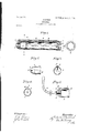
- igure 1 is a central longitudinal section of my apparatus.
- Fig. 2 is a rear view of the nozzle portion at right angles to the View of Fig. 1.
- Fig. 3 is a cross-section on y y of Fig. 1.
- Fig. 4 is an end view of the device.
- Fig. 5 is a modification of the device.
- A represents the casing or barrel of the syringe, made of any suitable material, but preferably of hard rubber. Since the diameter of the barrel is limited by nature, the walls are made as .thin as is consistent with necessary strength in order to provide as large a piston-chamber as possible.
- the forward end of the barrel terminates in a rounded and slightly-tapered nozzle, which is essentially ovoidal in cross-sectionand which has a central suction-inlet 2.
- the rear of the barrel is closed by a screw-cap 3, in which slides the suitably-packed piston-rod 4, having the piston 5 at its inner end and the handle 6 at its outer end.
- the flexible, compressive, and at the same 7 time coherent quality of the leather renders it particularly suitable for packing in a doubleaction syringe, while the small size of the piston-rod and the small amount of pressure actually exerted on the packing enables the rings 8 8' to be held in place without other means than the beveled walls of'the recesses.
- the sides of the protuberant part 9 are inclined'so as gradually to run into the sides of the barrel proper, a cross-section of the latter being essentially ovoidal with slightlyflattened sides.
- This construction admits of maximum water capacity. It is, furthermore, important because it insures insertion into the cavity along lines of least resistance.
- pi'ston-syr- 199' inges of this general type with either inner and outer concentric, chambers connected at the rear end and having discharge and suction openings at the opposite end or with an inner piston-chamber and a concentric annular series 'of ducts bored in the chamber-walls parallel with the axis of the chamber and opening into the rear end of the latter and having discharge and suction openings at the opposite end of.
- the construction of my device withits thin walls, except for the longitudinal and transversely-tapered protuberant portion 9, allows for a water-chamber of maximum capacity consistent with physiological conditions.
- the syringe is inserted into the cavity always with the part.9 uppermost.
- the barrel-space behind the piston first having been filled with water or other liquid in the usual manner, when the handle 6 is drawn outward the contents of the syringe are discharged through passage 10 above the orifice 2.
- the surrounding walls of the cavity embrace the nozzle and cooperate with it, so that the contents of the syringe are ejected into the cavity to effect the necessary cleansing,and conjointly thefluids of the cavity with its foreign matters are drawn into the syringe throughorifice 2.
- the tissues close over the orifice 2 still remains in communication with passage 10 through slit or groove 11, whereas even though the proper suction process is interfered with the water from passage 10 will pass back into the syringe and not into the cavity to escape around the outside of the barrel to the annoyance of the pa tient.
- the single outlet-passage 10 prevents any air passing back into the barrel to allow the syringe to leak after it is filled and during handling before insertion.
- Fig. 5 In Fig. 5 is shown a modification of the nozzle. in which the groove 11 is somewhat shallower and wider, and the passage 10 and orifice 2 are connected by a channel 12 for the same purpose of preventing escape of liquid around the outside of the barrel.
- a further advantage of this syringe over others commonly in use is the fact that it requires two strokes only to fill it, one upstroke to'cxpel the air from the space behind the piston and simultaneously to fill the space in front of the piston with water and one downstroke expelling the water previously drawn in and sucking water into the space behind the piston.
- This syringe may be quickly transformed from a vaginal to a rectal syringe by means of a suitable reducer 13, having a suitable screw-threaded portion engaging the corresponding threaded walls of orifice 2.
- the piston-rod In order to provide as large a water-space as possible behind the piston and, furthermore, to decrease the chance of leakage around the piston-rod and to provide a smooth action with the leather packing-rings,1 prefer to construct the piston-rod of metal. This allows the use of a rod one-half the size of one of rubher, while the metal lacks the tendency of ru bber to stick when in contact with leather.
- a syringe comprising a barrel portion inclosing two parallel chambers connected at or near their rear ends and each having adischarge-opening at their forward ends, the said discharge-openings connected by a lateral passage made in the front extremityof the barrel whereby said chambers may discharge one into the other in case the-outlet ends of said discharge-openings become closed, and a piston operatable in one of said chambers.
- a syringe comprising in combination a barrel having a blunt rounded nozzle portion, said nozzle portion essentially ovoidal in crosssection and having a central orifice and a substantially transverse groove forming a lateral passage-way, a piston movable in said barrel, said lateral passage-way connecting the rear end of the barrel-chamber with the nozzle-orifice and also having a discharge separate from but adjacent to said orifice.
Landscapes
- Health & Medical Sciences (AREA)
- Heart & Thoracic Surgery (AREA)
- Biomedical Technology (AREA)
- Vascular Medicine (AREA)
- Engineering & Computer Science (AREA)
- Anesthesiology (AREA)
- Pulmonology (AREA)
- Hematology (AREA)
- Life Sciences & Earth Sciences (AREA)
- Animal Behavior & Ethology (AREA)
- General Health & Medical Sciences (AREA)
- Public Health (AREA)
- Veterinary Medicine (AREA)
- Infusion, Injection, And Reservoir Apparatuses (AREA)
Description
No. 754,276. PATENTED MAR. 8, 1904.
' E. BARTSOH.
SYRINGE APPLICATION FILED JULY 7, 1903.
N0 MODEL.
IIIIIIIIIIIIIIIIII/l Patented March a, 1904.
UNITED STATES PATENT OFFICE.
EDWIN BARTSCH, OF SAN FRANCISCO, CALIFORNIA.
SYRINGE.
SPECIFICATION forming ,part of Letters Patent No. 754,276, dated March 8, 1904.
. Application filed July 7, 1903. Serial No. 164,513. (No model.)
To all whom it may concern.-
Be it known that I, EDWIN BARTSCH, a citizen of the United States, residing in the city and county of San Francisco, State of California, have invented an Improvement in Syringes; andI hereby declare the following to be a full, clear, and exact description of the same.
My invention relates to improvements in syringes of the piston type, and particularly those used in the treatment of female diseases and which are adapted to coactwith the va gina to discharge Water or a medicated fluid thereinto and simultaneously to withdraw into the syringe all foreign matters and excretions that may adhere to the uterus.
The object of my invention is to provide a syringe of simple construction and of small cost as compared with those'commonlyin use,
which will have a maximum capacity and be of a minimum size, which will not leak when filled, and which will be easy of manipulation and effective in operation;
It consists of the parts and the construction andoperation of parts as hereinafter more fully described, having reference to the accompanying drawings, in Which' igure 1 is a central longitudinal section of my apparatus. Fig. 2 is a rear view of the nozzle portion at right angles to the View of Fig. 1. Fig. 3 is a cross-section on y y of Fig. 1. Fig. 4 is an end view of the device. Fig. 5 is a modification of the device.
A represents the casing or barrel of the syringe, made of any suitable material, but preferably of hard rubber. Since the diameter of the barrel is limited by nature, the walls are made as .thin as is consistent with necessary strength in order to provide as large a piston-chamber as possible. The forward end of the barrel terminates in a rounded and slightly-tapered nozzle, which is essentially ovoidal in cross-sectionand which has a central suction-inlet 2. y The rear of the barrel is closed by a screw-cap 3, in which slides the suitably-packed piston-rod 4, having the piston 5 at its inner end and the handle 6 at its outer end. I
I have here shown a special form of packing designed especially for syringes of this type,
' having the objects in view of cleanliness, free- ,dom from leak, compactness, and durability.
Heretofore it has been common to use a stufling-box filled with a soft packing which is compressed by a gasket. The objection to this style of packing is particularly that in order to suitably compress the packing to prevent leak the oil is squeezed out and the piston-rod is smeared from end to end. The gasket becomes set so tight as not to be readily adjustable, and its several angles and crevices washers 8 8', having a normally greater di' 5 ameter than the reduced mouth of the recesses,
are forced and compressed into and seated in these recesses and are adapted to have a snug sliding fit on the piston-rod.
, The flexible, compressive, and at the same 7 time coherent quality of the leather renders it particularly suitable for packing in a doubleaction syringe, while the small size of the piston-rod and the small amount of pressure actually exerted on the packing enables the rings 8 8' to be held in place without other means than the beveled walls of'the recesses.
In order to connect the discharge end of the barrel with the space behind the piston, whereby fluid may be drawn in alternately to the spaceonone side or the other of the piston and be discharged therefrom at points adjacent to each other, I form the barrel with a thickened preferably integral portion 9, which extends along one side only of the barrel and 5' which has the longitudinal passage or duct 10. Passage 10 opens into the interior of the barrel near the-rear end thereof and discharges exterior to the barrel and adjacent to orifice 2;
but it is connected with the latter by a slit or 9 deep narrow groove 11.
Preferably the sides of the protuberant part 9 are inclined'so as gradually to run into the sides of the barrel proper, a cross-section of the latter being essentially ovoidal with slightlyflattened sides. This construction admits of maximum water capacity. It is, furthermore, important because it insures insertion into the cavity along lines of least resistance.
It has been common to construct pi'ston-syr- 199'": inges of this general type with either inner and outer concentric, chambers connected at the rear end and having discharge and suction openings at the opposite end or with an inner piston-chamber and a concentric annular series 'of ducts bored in the chamber-walls parallel with the axis of the chamber and opening into the rear end of the latter and having discharge and suction openings at the opposite end of.
the barrel. Types of such syringes are shown, respectively, inPatents No.407,934:, of July 30, 1889, and No. 443,083, of December 16, 1890. The objections to these forms of syringes, aside from cost of manufacture and their tend ency to leak when held otherwise than perpendicular, is the large diameter of the barrel necessary in order that the syringe may hold a suflicient quantity of water to be at all effective.
' Since the diameter of a barrel is limited by physiological conditions, small-size syringes of this character are impracticable. Moreover, with the plurality of discharge-holes around the larger center suction-inlet the tendency in actual practice is for the suction to act quicker than the discharge and the suctionorifices to be closed by the tissues of the cavity before the syringe has fully ejected its contents, and the proper cooperation of suction and discharge of the syringe is thereby seriously interfered with.
The construction of my device withits thin walls, except for the longitudinal and transversely-tapered protuberant portion 9, allows for a water-chamber of maximum capacity consistent with physiological conditions. The syringe is inserted into the cavity always with the part.9 uppermost. The barrel-space behind the piston first having been filled with water or other liquid in the usual manner, when the handle 6 is drawn outward the contents of the syringe are discharged through passage 10 above the orifice 2. The surrounding walls of the cavity embrace the nozzle and cooperate with it, so that the contents of the syringe are ejected into the cavity to effect the necessary cleansing,and conjointly thefluids of the cavity with its foreign matters are drawn into the syringe throughorifice 2.
If for any reason the tissues close over the orifice 2, the latter still remains in communication with passage 10 through slit or groove 11, whereas even though the proper suction process is interfered with the water from passage 10 will pass back into the syringe and not into the cavity to escape around the outside of the barrel to the annoyance of the pa tient. Moreover, the single outlet-passage 10 prevents any air passing back into the barrel to allow the syringe to leak after it is filled and during handling before insertion.
, In Fig. 5 is shown a modification of the nozzle. in which the groove 11 is somewhat shallower and wider, and the passage 10 and orifice 2 are connected by a channel 12 for the same purpose of preventing escape of liquid around the outside of the barrel.
A further advantage of this syringe over others commonly in use is the fact that it requires two strokes only to fill it, one upstroke to'cxpel the air from the space behind the piston and simultaneously to fill the space in front of the piston with water and one downstroke expelling the water previously drawn in and sucking water into the space behind the piston.
This syringe may be quickly transformed from a vaginal to a rectal syringe by means of a suitable reducer 13, having a suitable screw-threaded portion engaging the corresponding threaded walls of orifice 2.
In order to provide as large a water-space as possible behind the piston and, furthermore, to decrease the chance of leakage around the piston-rod and to provide a smooth action with the leather packing-rings,1 prefer to construct the piston-rod of metal. This allows the use of a rod one-half the size of one of rubher, while the metal lacks the tendency of ru bber to stick when in contact with leather.
Having thus described my invention, what I claim, and desire to secure by Letters Patcut, is-- V 1. A syringe comprising a barrel portion inclosing two parallel chambers connected at or near their rear ends and each having adischarge-opening at their forward ends, the said discharge-openings connected by a lateral passage made in the front extremityof the barrel whereby said chambers may discharge one into the other in case the-outlet ends of said discharge-openings become closed, and a piston operatable in one of said chambers.
52. A syringe comprising in combination a barrel having a blunt rounded nozzle portion, said nozzle portion essentially ovoidal in crosssection and having a central orifice and a substantially transverse groove forming a lateral passage-way, a piston movable in said barrel, said lateral passage-way connecting the rear end of the barrel-chamber with the nozzle-orifice and also having a discharge separate from but adjacent to said orifice.
3. In a syringe of the double-action type, the combination with the barrel and piston-rod thereofof a perforated cap attaching to the barrel and embracing the piston-rod, and flexible packing-rings carried by said cap and engaging the rod inside and outside the barrel and separated by an annulus rigid with the cap.
4.. In a syringe of the double-action type, the combination with the barrel and piston=rod thereof, of a cap attaching to the barrel and embracing the piston-rod, said cap having annular recesses concentric with the rod, on the inner and outer side of the cap, said recesses having substantially dovetailed walls,and flexi-v ble packing-rings with edges inclined correspondingly with the walls of said recesses seating in the latter and held therein solely by the interengagement of said edges and walls.
5. The combination in a syringe, of a barrel IIO characterized by havinga cylindrical bore and being essentially ovoidal in cross-section'and terminating in a nozzle portion with slightlyfl'attened sides, a passage-way in the thickened wall portion of said barrel extending parallel with the bore and opening into the rear end of the barrel and discharging at a point adjacent to the nozzle-orifice.
6. In a syringe, the combination of a hardrubber shell inclosing a piston-chamber and a lateral passage, said passage opening into the rear end of said chamber and having a point of discharge in common with the chamber, a piston, a metal piston-rod of reduced diameter,
and a perforated cap attaching to the shell and I5 EDWIN BARTSCH.
Witnesses:
S. H. NOURSE, J ESSIE C. BRODIE.
Priority Applications (1)
| Application Number | Priority Date | Filing Date | Title |
|---|---|---|---|
| US16451303A US754276A (en) | 1903-07-07 | 1903-07-07 | Syringe. |
Applications Claiming Priority (1)
| Application Number | Priority Date | Filing Date | Title |
|---|---|---|---|
| US16451303A US754276A (en) | 1903-07-07 | 1903-07-07 | Syringe. |
Publications (1)
| Publication Number | Publication Date |
|---|---|
| US754276A true US754276A (en) | 1904-03-08 |
Family
ID=2822769
Family Applications (1)
| Application Number | Title | Priority Date | Filing Date |
|---|---|---|---|
| US16451303A Expired - Lifetime US754276A (en) | 1903-07-07 | 1903-07-07 | Syringe. |
Country Status (1)
| Country | Link |
|---|---|
| US (1) | US754276A (en) |
Cited By (1)
| Publication number | Priority date | Publication date | Assignee | Title |
|---|---|---|---|---|
| US3841330A (en) * | 1972-05-16 | 1974-10-15 | K Storz | Method and apparatus for bathing body cavities |
-
1903
- 1903-07-07 US US16451303A patent/US754276A/en not_active Expired - Lifetime
Cited By (1)
| Publication number | Priority date | Publication date | Assignee | Title |
|---|---|---|---|---|
| US3841330A (en) * | 1972-05-16 | 1974-10-15 | K Storz | Method and apparatus for bathing body cavities |
Similar Documents
| Publication | Publication Date | Title |
|---|---|---|
| US452131A (en) | Depurator | |
| US3398743A (en) | Closed system irrigating apparatus for viscus organs | |
| US4891044A (en) | Ophthalmic aspirating/irrigating device | |
| US1496126A (en) | Syringe | |
| US2879768A (en) | Two-way ear syringe | |
| IT8268522A1 (en) | GROUP COMPRISING AN ELASTOMERIC BLADDER, PARTICULARLY FOR MEDICAL INFUSERS. | |
| US2170599A (en) | Veterinary dose gun | |
| US4693709A (en) | Syringe | |
| US754276A (en) | Syringe. | |
| US2180063A (en) | Syringe | |
| US342131A (en) | Island | |
| US2098106A (en) | Syringe | |
| US2605026A (en) | Dispensing cap for collapsible tubes | |
| US1331271A (en) | Syringe | |
| US877926A (en) | Vaginal syringe. | |
| US1534852A (en) | Syringe | |
| US1624990A (en) | Surgical syringe | |
| US1188417A (en) | Dental instrument. | |
| US972201A (en) | Syringe. | |
| US735276A (en) | Vaginal syringe. | |
| US497250A (en) | George s | |
| US458774A (en) | Ridge | |
| US1521890A (en) | Hypodermic syringe | |
| US931113A (en) | Syringe. | |
| US443083A (en) | Syringe |