US753232A - Dumping-wagon - Google Patents
Dumping-wagon Download PDFInfo
- Publication number
- US753232A US753232A US753232DA US753232A US 753232 A US753232 A US 753232A US 753232D A US753232D A US 753232DA US 753232 A US753232 A US 753232A
- Authority
- US
- United States
- Prior art keywords
- bottom sections
- wagon
- sections
- chains
- elbow
- Prior art date
- Legal status (The legal status is an assumption and is not a legal conclusion. Google has not performed a legal analysis and makes no representation as to the accuracy of the status listed.)
- Expired - Lifetime
Links
- 238000010276 construction Methods 0.000 description 6
- 210000001513 Elbow Anatomy 0.000 description 2
- 240000003670 Sesamum indicum Species 0.000 description 2
- 230000000694 effects Effects 0.000 description 2
- 238000004519 manufacturing process Methods 0.000 description 2
- 238000000926 separation method Methods 0.000 description 2
- 238000004804 winding Methods 0.000 description 2
Images

Classifications
-
- B—PERFORMING OPERATIONS; TRANSPORTING
- B60—VEHICLES IN GENERAL
- B60P—VEHICLES ADAPTED FOR LOAD TRANSPORTATION OR TO TRANSPORT, TO CARRY, OR TO COMPRISE SPECIAL LOADS OR OBJECTS
- B60P1/00—Vehicles predominantly for transporting loads and modified to facilitate loading, consolidating the load, or unloading
- B60P1/56—Vehicles predominantly for transporting loads and modified to facilitate loading, consolidating the load, or unloading the load-transporting element having bottom discharging openings
Definitions
- n4 oasis PETERS cor. whom-umm wAsilun'mN. o, cv
- My invention relates to dumping-wagons of the kind in which the bottom of the wagon box or body is divided longitudinally to form a couple of bottom sections, which are hingeconnected with opposite ksides of the wagonbody. ⁇ These hinged bottom sections when held in a horizontal plane common to both serve as a bottom for the wagon-body, and when released they will be caused to swing downwardly by the weight of the load, and thereby open the body at its bottom and permit the load to dump.
- the hinged bottom sections are controlled by raising and lowering chains or cables connected with windin g mechanism, so that when the chains areallowed to pay out the bottom sections will swing downwardly, while, on the other hand, when the chains or cables are wound up the bottom sections will be swung upwardly, so as to bring them into position for forming a closed bottom for the wagon-body.
- the outer edges of the bottom boards are hinged to the lower edges of the sides of the body by pintle-hinges, so that when the load is dumped the bottom sections can swing downwardly and laterally outward to an eX- tent to drop into vertical planes at opposite sides of the dump, while in others this result has been attained by attaching suspendingchains to the sides of the body at points higher than the bottom level thereof and connecting these suspending-chains with the bottom sections, the latter being thereby, in effect, .hingeconnected with the body by means of such suspending-chains.
- Objects of my invention are to permit the bottom sections to swing downwardly and laterally outward and at the same time to cause such swinging sections to bodily rise, so as to leave more space between them and the ground for any lateral spread of the dumped material;
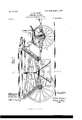
- Figure 1 is a longitudinal central section, on a vertical plane, through a dumping-wagon embodying the principles of my invention.
- Fig. 2 is a section through Fig. l on line 2X 2X with the bottom sections in an open condition.
- Fig. 3 is a like view with the bottom sections closed.
- the wagon boxor body A is supported as usual or in any suitable way by front and rear wheels B C and is constructed with an open bottomthat is to say, it is constructed'with sides and ends and provided with a couple of longitudinally-hinged bottom sectionsD D, which are hinge-connected with opposite sides of the body andl arranged so that when swung into theposition shown in Fig. 2 the body will be open at its bottom, and when swung ⁇ into the position shown in Fig. 3 the body will be closed at its bottom by the two hinged sections, which when in such position provide a temporary bottom.
- These swinging bottom sections D are hinged to bent or elbow arms E, which are in turn hinged or pivoted upon the longitudinal sides of the wagon box or between the longitudinal edges of such sections.
- the arm portions 2 of the elbow-arms have relatively separated from the portions of the bottom sections which lapped overor upon them when the bottom sections occupied the position shown in Fig. 3, and it will also be seen that when the parts-referred yto have reached the position shown in Fig. 2 the bottom sections have their outer edges somewhat higher than the lower edges of the sides of the box or body. This rise on the part of the bottom sections can be increased by raising the points at which the elbow-arms are pivotally supported and correspondingly lengthening portions 1 of the elbow-arms to permit their portions 2 to lap under the bottom sections when the latter are closed, as in Fig.
- the spread of the rear wheels can be proportionally increased or the width ofthe box or body can be proportionallycontracted, so as to provide between the sides of the body and the rear wheels ample clearance-space for swing on the part of the elbow-arms.
- the points at which these elbow-arms are hinge-connected with the under sides of the bottom sections can also be varied-as, for example, such point or connection may be midway of the longitudinal edges of each bottom section or between such middle point and either longitudinal edge-and obviously the arrangementl could be such that the outer longitudinal edge por'- tions of the bottom sections in place of lapping the outer faces of the sides of the box or body, as in Fig.
- the extent to which the bottom sections can swing laterally outward can be determined by the length of the chains, and, if desired, the proportions of the operative members described can be readily varied, so as to permit the bot-v tom sections, as shown in Fig. 2, to swing farther outward or toward the wheels, this further or increased extent of swing being an obvious possibility consistent with the principles of construction illustrated.
- the bottom sectionsr can be restored from the position shown in Fig. 2 to the position shown in Fig. 3 by drawing the chains G forwardly-for example, by swinging them upon a drum or rotary winding-shaft-whereby the chains F will be drawn upwardly, so as to raise the bottom sections.
- the bottom sections will also tilt in a direction to cause them to lap the arm portions 2 of the elbow-arms, and thereby permit the chains to swing both the bottom sections and the elbowarms into the position shown in Fig. 3.
- elbow-arms having upper arm portions pivotally or hinge supported'at opposite Sides of the wagon-body; bottom sections hinged upon the lower arm portions of such elbow-arms, and chains F attached in pairs to the bottom sections and converging upwardly to and connected with chains GU ARTHUR CAMERON.
Landscapes
- Engineering & Computer Science (AREA)
- Transportation (AREA)
- Mechanical Engineering (AREA)
- Handcart (AREA)
Description
No. 753,232. PATENTBD MAR. 1, 1904. A.l CAMERON.
DUMPING WAGoN.
APPLICATION FILED JULY 13. 1903. v N0 MODEL. 2 SHEETS-SHEET 1.
` M "I A l Y g |l l 1,1 z L y f l, -4, Il l n Til i r---- l www EVER;
PAIENTBD MAR'. l, 1904.
A. CAMERON. DUMPING WAGON. -APPLIUMION HLBDJULY 1a. 190s.-
2 SHBETS--SHEBT 2.
N0 MODEL.
n4: oasis PETERS cor. whom-umm wAsilun'mN. o, cv
UNITED 'STATES Patented March 1, 1904.
PATENT OFFICE.
ARTHUR CAMERON, OF CHICAGO, ILLINOIS, ASSIGNOR VTO NATIONAL DRILL AND MANUFACTURING COMPANY, OF CHICAGO, ILLINOIS, AA CORPORATION OF WEST VIRGINIA.
SPECIFICATION forming part of Letters Patent No. 753,232, dated March 1, 1904.
Application led July 13, 1903. Serial Not 165,312. (No model.)
To all whom it may concern.'
, Be it known that I, ARTHUR CAMERON, acitizen of the United States, residing at Chicago, in the county of Cook and State of Illinois, have invented certain new and useful Improvements in Dnmping-I'Vagons, of which the following is a specification.
My invention relates to dumping-wagons of the kind in which the bottom of the wagon box or body is divided longitudinally to form a couple of bottom sections, which are hingeconnected with opposite ksides of the wagonbody.` These hinged bottom sections when held in a horizontal plane common to both serve as a bottom for the wagon-body, and when released they will be caused to swing downwardly by the weight of the load, and thereby open the body at its bottom and permit the load to dump. In various dumpingwagons of such class the hinged bottom sections are controlled by raising and lowering chains or cables connected with windin g mechanism, so that when the chains areallowed to pay out the bottom sections will swing downwardly, while, on the other hand, when the chains or cables are wound up the bottom sections will be swung upwardly, so as to bring them into position for forming a closed bottom for the wagon-body.- In some of these wagons the outer edges of the bottom boards are hinged to the lower edges of the sides of the body by pintle-hinges, so that when the load is dumped the bottom sections can swing downwardly and laterally outward to an eX- tent to drop into vertical planes at opposite sides of the dump, while in others this result has been attained by attaching suspendingchains to the sides of the body at points higher than the bottom level thereof and connecting these suspending-chains with the bottom sections, the latter being thereby, in effect, .hingeconnected with the body by means of such suspending-chains.
Objects of my invention are to permit the bottom sections to swing downwardly and laterally outward and at the same time to cause such swinging sections to bodily rise, so as to leave more space between them and the ground for any lateral spread of the dumped material;
-to widen the space between the bottom sections when they are permitted to hang from their hinge connections with the wagon-body;
to prevent material from collecting on the outer edges of the bottom sections when the latter swing into position to bring such edges uppermost; to dislodge material from the upper sides of the bottom sections in dumping; to place the hinge connection between the bottom sections and the body out of the way of materials contained within and dumped from the wagon-body; to eectively close the bottom of the wagon-body, and to provide certain novel `and improved details serving to'increase the general eiiiciency of dumpingwagons.
In the accompanying drawings, 'Figure 1 is a longitudinal central section, on a vertical plane, through a dumping-wagon embodying the principles of my invention. Fig. 2 is a section through Fig. l on line 2X 2X with the bottom sections in an open condition. Fig. 3 is a like view with the bottom sections closed.
The wagon boxor body A is supported as usual or in any suitable way by front and rear wheels B C and is constructed with an open bottomthat is to say, it is constructed'with sides and ends and provided with a couple of longitudinally-hinged bottom sectionsD D, which are hinge-connected with opposite sides of the body andl arranged so that when swung into theposition shown in Fig. 2 the body will be open at its bottom, and when swung `into the position shown in Fig. 3 the body will be closed at its bottom by the two hinged sections, which when in such position provide a temporary bottom. These swinging bottom sections D are hinged to bent or elbow arms E, which are in turn hinged or pivoted upon the longitudinal sides of the wagon box or between the longitudinal edges of such sections. The arrangement of these hinged connections between the bottom sections and the box or body is such that when the bottomsections are in `position to close the body at its bottom or form a temporary bottom therefor, as in Fig. 3, the lower arm portions 2 of the elbow-arm E will underlap and preferably lie against or adjacent to the under sides of the bottom sections. When, however, the bottom sections are released or permitted to swing downwardly, the elbow-arms E will swing outwardly, and the bottom sections While swinging downwardly and apart by reason of their own weight and the weight of the load will also relatively tilt upon the ends of the elbow-arms to which they are hinged, whereby'relative separation will take place between the arm portions 2 of the'elbow-arms and the portions of the bottom section which lapped over or upon such arm portions when the bottom sections occupied the position shown in Fig. 3. Y
As shown in Fig. 2, the arm portions 2 of the elbow-arms have relatively separated from the portions of the bottom sections which lapped overor upon them when the bottom sections occupied the position shown in Fig. 3, and it will also be seen that when the parts-referred yto have reached the position shown in Fig. 2 the bottom sections have their outer edges somewhat higher than the lower edges of the sides of the box or body. This rise on the part of the bottom sections can be increased by raising the points at which the elbow-arms are pivotally supported and correspondingly lengthening portions 1 of the elbow-arms to permit their portions 2 to lap under the bottom sections when the latter are closed, as in Fig. 3, it being observed that with such arrangement the spread of the rear wheels can be proportionally increased or the width ofthe box or body can be proportionallycontracted, so as to provide between the sides of the body and the rear wheels ample clearance-space for swing on the part of the elbow-arms. The points at which these elbow-arms are hinge-connected with the under sides of the bottom sections can also be varied-as, for example, such point or connection may be midway of the longitudinal edges of each bottom section or between such middle point and either longitudinal edge-and obviously the arrangementl could be such that the outer longitudinal edge por'- tions of the bottom sections in place of lapping the outer faces of the sides of the box or body, as in Fig. 2, will come below the lower edge of such sides of the box or body when the bottom sections are in the position shown in said figure and that by increasing the spread of the rear wheels the force of the dumping action can be permitted to swing the bottom sections into downwardly-diverging planes. In all of such variations of proportion and adjustment, however, the bottom sections are hinged to the swinging elbow-arms, which are in turn pivotally suspended 'at opposite sides of the box or body.
While I do not limit myself to any one particular construction or arrangement of device or mechanism for raising the bottom sections from their lowered positions to the raised position shown in Fig. 2, I have shown as a means for thus operating the bottom sections two pairs of chains F, respectively, for each bottom section, as best shown in Fig. 1, in which the twoA chains of one of such pairs of chains have their lower ends attached to one of the bottom sections near the ends of such bottom section. With such arrangement the two chains thus attached converge upwardly and connect with a single chain G, which passes through an opening in the side of the box or body and thence extends forwardly to any suitable winding and unwinding device. This arrangement of chains is duplicated, so as to provide means for operating each bottom section. When chains are thus used, the extent to which the bottom sections can swing laterally outward can be determined by the length of the chains, and, if desired, the proportions of the operative members described can be readily varied, so as to permit the bot-v tom sections, as shown in Fig. 2, to swing farther outward or toward the wheels, this further or increased extent of swing being an obvious possibility consistent with the principles of construction illustrated.
After the load has been dumped the bottom sectionsr can be restored from the position shown in Fig. 2 to the position shown in Fig. 3 by drawing the chains G forwardly-for example, by swinging them upon a drum or rotary winding-shaft-whereby the chains F will be drawn upwardly, so as to raise the bottom sections. During this operation the bottom sections will also tilt in a direction to cause them to lap the arm portions 2 of the elbow-arms, and thereby permit the chains to swing both the bottom sections and the elbowarms into the position shown in Fig. 3.
I am aware that Letters Patent of the United States No. 17 7,324, granted to D. J. Deen and dated May 10, 1876, shows the bottom of a wagon box or body secured and permanently held iiatwise upon the lower portions of swinging elbow-arms and that such feature of construction is also illustrated in Letters Patent of the United States No. 378,272, granted to D. S. Watson and dated February 21, 1888. In said patents, however, the bottom boards or sections are not hinged to the swinging elbow-arms, and hence the results and advantages of my improvement are not therein attained. i
What I claim as my invention is- 1. In a dumping-wagon, a bottom for the wagon-body comprising longitudinal bottom sections hinged to the lower arm portions of swinging elbow-arms which have their upper IOO IIO
the bottom sections attached to the latter at or near their free end portions.
4. In a dumping-wagon, elbow-arms having upper arm portions pivotally or hinge supported'at opposite Sides of the wagon-body; bottom sections hinged upon the lower arm portions of such elbow-arms, and chains F attached in pairs to the bottom sections and converging upwardly to and connected with chains GU ARTHUR CAMERON.
Witnesses:
CHARLES G. PAGE, Otrcrmrn C. FRELBRRG.
Publications (1)
| Publication Number | Publication Date |
|---|---|
| US753232A true US753232A (en) | 1904-03-01 |
Family
ID=2821725
Family Applications (1)
| Application Number | Title | Priority Date | Filing Date |
|---|---|---|---|
| US753232D Expired - Lifetime US753232A (en) | Dumping-wagon |
Country Status (1)
| Country | Link |
|---|---|
| US (1) | US753232A (en) |
-
0
- US US753232D patent/US753232A/en not_active Expired - Lifetime
Similar Documents
| Publication | Publication Date | Title |
|---|---|---|
| US663989A (en) | Shutter for doors or windows. | |
| US753232A (en) | Dumping-wagon | |
| US1897175A (en) | Automatic flat-bottom unloading device | |
| US718742A (en) | Coke-oven lorry. | |
| US888793A (en) | Dumping-wagon. | |
| US774978A (en) | Dumping-wagon. | |
| US870929A (en) | Dumping-wagon. | |
| US939758A (en) | Wagon-bed. | |
| US468794A (en) | Dumping-wagon | |
| US1458047A (en) | Dump wagon | |
| US882868A (en) | Coal-delivery wagon. | |
| US894003A (en) | Dumping-wagon. | |
| US1555760A (en) | Grain-bin attachment for harvester-thrashers | |
| US880054A (en) | Dumping-wagon. | |
| US956078A (en) | Grain-car door. | |
| US795172A (en) | Dumping-wagon. | |
| US843284A (en) | Dumping-wagon. | |
| US717701A (en) | Loading attachment for wagons. | |
| US1002174A (en) | Wagon-box. | |
| US857943A (en) | Dumping-wagon. | |
| US1023190A (en) | Side-dump body. | |
| US1035011A (en) | Wagon-gate. | |
| US682343A (en) | Dump-car. | |
| US94988A (en) | Improved dttmfing-cart | |
| US791944A (en) | Coke-grapple. |