US7482086B2 - Electrochemical polymer electrolyte membrane cell stacks and manufacturing methods thereof - Google Patents
Electrochemical polymer electrolyte membrane cell stacks and manufacturing methods thereof Download PDFInfo
- Publication number
- US7482086B2 US7482086B2 US11/229,087 US22908705A US7482086B2 US 7482086 B2 US7482086 B2 US 7482086B2 US 22908705 A US22908705 A US 22908705A US 7482086 B2 US7482086 B2 US 7482086B2
- Authority
- US
- United States
- Prior art keywords
- fuel cell
- stack
- opening
- housing
- cassette
- Prior art date
- Legal status (The legal status is an assumption and is not a legal conclusion. Google has not performed a legal analysis and makes no representation as to the accuracy of the status listed.)
- Expired - Lifetime
Links
Images


Classifications
-
- H—ELECTRICITY
- H01—ELECTRIC ELEMENTS
- H01M—PROCESSES OR MEANS, e.g. BATTERIES, FOR THE DIRECT CONVERSION OF CHEMICAL ENERGY INTO ELECTRICAL ENERGY
- H01M8/00—Fuel cells; Manufacture thereof
- H01M8/02—Details
- H01M8/0271—Sealing or supporting means around electrodes, matrices or membranes
-
- H—ELECTRICITY
- H01—ELECTRIC ELEMENTS
- H01M—PROCESSES OR MEANS, e.g. BATTERIES, FOR THE DIRECT CONVERSION OF CHEMICAL ENERGY INTO ELECTRICAL ENERGY
- H01M8/00—Fuel cells; Manufacture thereof
- H01M8/02—Details
- H01M8/0202—Collectors; Separators, e.g. bipolar separators; Interconnectors
- H01M8/0258—Collectors; Separators, e.g. bipolar separators; Interconnectors characterised by the configuration of channels, e.g. by the flow field of the reactant or coolant
-
- H—ELECTRICITY
- H01—ELECTRIC ELEMENTS
- H01M—PROCESSES OR MEANS, e.g. BATTERIES, FOR THE DIRECT CONVERSION OF CHEMICAL ENERGY INTO ELECTRICAL ENERGY
- H01M8/00—Fuel cells; Manufacture thereof
- H01M8/02—Details
- H01M8/0202—Collectors; Separators, e.g. bipolar separators; Interconnectors
- H01M8/0267—Collectors; Separators, e.g. bipolar separators; Interconnectors having heating or cooling means, e.g. heaters or coolant flow channels
-
- H—ELECTRICITY
- H01—ELECTRIC ELEMENTS
- H01M—PROCESSES OR MEANS, e.g. BATTERIES, FOR THE DIRECT CONVERSION OF CHEMICAL ENERGY INTO ELECTRICAL ENERGY
- H01M8/00—Fuel cells; Manufacture thereof
- H01M8/02—Details
- H01M8/0271—Sealing or supporting means around electrodes, matrices or membranes
- H01M8/028—Sealing means characterised by their material
- H01M8/0284—Organic resins; Organic polymers
-
- H—ELECTRICITY
- H01—ELECTRIC ELEMENTS
- H01M—PROCESSES OR MEANS, e.g. BATTERIES, FOR THE DIRECT CONVERSION OF CHEMICAL ENERGY INTO ELECTRICAL ENERGY
- H01M8/00—Fuel cells; Manufacture thereof
- H01M8/02—Details
- H01M8/0271—Sealing or supporting means around electrodes, matrices or membranes
- H01M8/0286—Processes for forming seals
-
- H—ELECTRICITY
- H01—ELECTRIC ELEMENTS
- H01M—PROCESSES OR MEANS, e.g. BATTERIES, FOR THE DIRECT CONVERSION OF CHEMICAL ENERGY INTO ELECTRICAL ENERGY
- H01M8/00—Fuel cells; Manufacture thereof
- H01M8/10—Fuel cells with solid electrolytes
- H01M8/1007—Fuel cells with solid electrolytes with both reactants being gaseous or vaporised
-
- H—ELECTRICITY
- H01—ELECTRIC ELEMENTS
- H01M—PROCESSES OR MEANS, e.g. BATTERIES, FOR THE DIRECT CONVERSION OF CHEMICAL ENERGY INTO ELECTRICAL ENERGY
- H01M8/00—Fuel cells; Manufacture thereof
- H01M8/24—Grouping of fuel cells, e.g. stacking of fuel cells
- H01M8/241—Grouping of fuel cells, e.g. stacking of fuel cells with solid or matrix-supported electrolytes
- H01M8/242—Grouping of fuel cells, e.g. stacking of fuel cells with solid or matrix-supported electrolytes comprising framed electrodes or intermediary frame-like gaskets
-
- H—ELECTRICITY
- H01—ELECTRIC ELEMENTS
- H01M—PROCESSES OR MEANS, e.g. BATTERIES, FOR THE DIRECT CONVERSION OF CHEMICAL ENERGY INTO ELECTRICAL ENERGY
- H01M8/00—Fuel cells; Manufacture thereof
- H01M8/24—Grouping of fuel cells, e.g. stacking of fuel cells
- H01M8/2465—Details of groupings of fuel cells
- H01M8/247—Arrangements for tightening a stack, for accommodation of a stack in a tank or for assembling different tanks
- H01M8/2475—Enclosures, casings or containers of fuel cell stacks
-
- H—ELECTRICITY
- H01—ELECTRIC ELEMENTS
- H01M—PROCESSES OR MEANS, e.g. BATTERIES, FOR THE DIRECT CONVERSION OF CHEMICAL ENERGY INTO ELECTRICAL ENERGY
- H01M8/00—Fuel cells; Manufacture thereof
- H01M8/24—Grouping of fuel cells, e.g. stacking of fuel cells
- H01M8/2465—Details of groupings of fuel cells
- H01M8/247—Arrangements for tightening a stack, for accommodation of a stack in a tank or for assembling different tanks
- H01M8/248—Means for compression of the fuel cell stacks
-
- H—ELECTRICITY
- H01—ELECTRIC ELEMENTS
- H01M—PROCESSES OR MEANS, e.g. BATTERIES, FOR THE DIRECT CONVERSION OF CHEMICAL ENERGY INTO ELECTRICAL ENERGY
- H01M8/00—Fuel cells; Manufacture thereof
- H01M8/24—Grouping of fuel cells, e.g. stacking of fuel cells
- H01M8/2465—Details of groupings of fuel cells
- H01M8/2483—Details of groupings of fuel cells characterised by internal manifolds
-
- H—ELECTRICITY
- H01—ELECTRIC ELEMENTS
- H01M—PROCESSES OR MEANS, e.g. BATTERIES, FOR THE DIRECT CONVERSION OF CHEMICAL ENERGY INTO ELECTRICAL ENERGY
- H01M8/00—Fuel cells; Manufacture thereof
- H01M8/24—Grouping of fuel cells, e.g. stacking of fuel cells
- H01M8/249—Grouping of fuel cells, e.g. stacking of fuel cells comprising two or more groupings of fuel cells, e.g. modular assemblies
-
- Y—GENERAL TAGGING OF NEW TECHNOLOGICAL DEVELOPMENTS; GENERAL TAGGING OF CROSS-SECTIONAL TECHNOLOGIES SPANNING OVER SEVERAL SECTIONS OF THE IPC; TECHNICAL SUBJECTS COVERED BY FORMER USPC CROSS-REFERENCE ART COLLECTIONS [XRACs] AND DIGESTS
- Y02—TECHNOLOGIES OR APPLICATIONS FOR MITIGATION OR ADAPTATION AGAINST CLIMATE CHANGE
- Y02E—REDUCTION OF GREENHOUSE GAS [GHG] EMISSIONS, RELATED TO ENERGY GENERATION, TRANSMISSION OR DISTRIBUTION
- Y02E60/00—Enabling technologies; Technologies with a potential or indirect contribution to GHG emissions mitigation
- Y02E60/30—Hydrogen technology
- Y02E60/50—Fuel cells
-
- Y—GENERAL TAGGING OF NEW TECHNOLOGICAL DEVELOPMENTS; GENERAL TAGGING OF CROSS-SECTIONAL TECHNOLOGIES SPANNING OVER SEVERAL SECTIONS OF THE IPC; TECHNICAL SUBJECTS COVERED BY FORMER USPC CROSS-REFERENCE ART COLLECTIONS [XRACs] AND DIGESTS
- Y02—TECHNOLOGIES OR APPLICATIONS FOR MITIGATION OR ADAPTATION AGAINST CLIMATE CHANGE
- Y02P—CLIMATE CHANGE MITIGATION TECHNOLOGIES IN THE PRODUCTION OR PROCESSING OF GOODS
- Y02P70/00—Climate change mitigation technologies in the production process for final industrial or consumer products
- Y02P70/50—Manufacturing or production processes characterised by the final manufactured product
Definitions
- This invention relates to electrochemical polymer electrolyte membrane (“PEM”) cells and stacks thereof, and more particularly, to PEM fuel cell stacks.
- PEM electrochemical polymer electrolyte membrane
- the present invention also describes novel processes for producing these PEM fuel cell stacks.
- Electrochemical PEM cells and particularly, PEM fuel cells are well known.
- PEM fuel cells convert chemical energy to electrical power with virtually no environmental emissions and differ from a battery in that energy is not stored, but derived from supplied fuel. Therefore, a fuel cell is not tied to a charge/discharge cycle and can maintain a specific power output as long as fuel is continuously supplied.
- the large investments into fuel cell research and commercialization indicate the technology has considerable potential in the marketplace.
- the high cost of fuel cells when compared to conventional power generation technology has deterred their potentially widespread use. Costs of fabricating and assembling fuel cells can be significant, due to the materials and labor involved, and as much as 85% of a fuel cell's price can be attributed to manufacturing costs.
- a single cell PEM fuel cell consists of an anode and a cathode compartment separated by a thin, ionically conducting membrane. This catalyzed membrane, with or without gas diffusion layers, is often referred to as a membrane electrode assembly (“MEA”).
- MEA membrane electrode assembly
- Energy conversion begins when the reactants, reductants and oxidants, are supplied to the anode and cathode compartments, respectively, of the PEM fuel cell.
- Oxidants include pure oxygen, oxygen containing gases, such as air, and halogens, such as chlorine.
- Reductants, also referred to herein as fuel include hydrogen, natural gas, methane, ethane, propane, butane, formaldehyde, methanol, ethanol, alcohol blends and other hydrogen rich organics.
- the reductant is oxidized to produce protons, which migrate across the membrane to the cathode.
- the protons react with the oxidant.
- the overall electrochemical redox (reduction/oxidation) reaction is spontaneous, and energy is released. Throughout this reaction, the PEM serves to prevent the reductant and oxidant from mixing and to allow ionic transport to occur.
- separator plates serve as current collectors for the electrodes and may also contain an array of lands and grooves formed in the surface of the plate contacting the MEA, in which case the separator plates are often referred to only as “bipolar plates” and the array of lands and grooves as “flow fields”. Alternatively, the flow field may be a separate porous electrode layer.
- Ideal separator plates for use in fuel cell stacks are thin, lightweight, durable, highly conductive, corrosion resistant structures that can also, if desired, provide effective flow fields and thereby become bipolar plates.
- the lands conduct current from the electrodes, while the grooves between the lands serve to distribute the gaseous reactants utilized by a fuel cell, such as hydrogen, oxygen or air, evenly over the faces of the electrodes.
- the channels formed by the lands and grooves also facilitate removal of liquid reaction byproducts, such as water.
- a thin sheet of porous paper, cloth or felt, usually made from graphite or carbon, may be positioned between each of the flow fields and the catalyzed faces of the MEA to support the MEA where it confronts grooves in the flow field to conduct current to the adjacent lands, and to aid in distributing reactants to the MEA.
- This thin sheet is normally termed a gas diffusion layer (“GDL”), and is incorporated as part of the MEA.
- GDL gas diffusion layer
- Fuel cell stacks may also contain humidification channels within one or more of the coolant flow fields. These humidification channels provide a mechanism to humidify fuel and oxidants at a temperature as close as possible to the operating temperature of the fuel cell. This helps to prevent dehydration of the PEM as a high temperature differential between the gases entering the fuel cell and the temperature of the PEM causes water vapor to be transferred from the PEM to the fuel and oxidant streams.
- the location of the humidification channels can either be upstream from the MEA, such as in the fuel cell stacks described in U.S. Pat. No. 5,382,478 to Chow et al., and U.S. Pat. No. 6,066,408 to Vitale et al., or downstream from the MEA, such as those described in U.S. Pat. No. 5,176,966 to Epp et al.
- certain stack components such as the GDL portion of the MEA, are porous in order to provide for the distribution of reactants and byproducts into, out of, and within the fuel cell stack. Due to the porosity of elements within the stack, a means to prevent leakage of any liquid or gases between stack components (or outside of the stack) as well as to prevent drying out of these porous elements due to exposure to the environment is also needed.
- gaskets or other seals are usually provided between the surfaces of the MEA and other stack components, such as flow fields, and on portions of the stack periphery. These sealing means, whether elastomeric or adhesive materials, are generally placed upon, fitted, formed or directly applied to the particular surfaces being sealed.
- Fuel cell stacks range in design depending upon power output, cooling, and other technical requirements, but may utilize a multitude of MEAs, seals, flow fields, and separator plates, in intricate assemblies that result in manufacturing difficulties and further increase fuel cell costs.
- one fuel cell stack described in U.S. Pat. No. 5,683,828, to Spear et al., employs bipolar plates containing up to ten separate layers adhesively bonded together, each layer having distinct channels that are dedicated to passing cooling water through the fuel cell stack for thermal management.
- U.S. Pat. No. 5,176,966, to Epp et al. describes a method of forming at least some of the required gaskets directly into the fuel cell stack assembly. Specifically, the MEA is made with corresponding carbon paper and then an extrudable sealant is applied into grooves cut within the carbon paper.
- U.S. Pat. No. 5,264,299, to Krasij et al. describes a fuel cell module having a PEM interposed between the two porous support layers which distribute reactant to the catalyst layers in which the peripheral portion of the support layers are sealed with an elastomeric material such that the PEM is joined with the support layers and the open pores of the support layers are filled with the elastomeric material making it fluid impermeable.
- the elastomeric material solidifies to form a fluid impermeable frame for the PEM and support layer assembly.
- U.S. Pat. No. 5,523,175, to Beal et al. describes an improvement of U.S. Pat. No. 5,264,299 which comprises a plurality of gas distribution channels on the support layers and utilizes a hydrophilic material for sealing of the open pores.
- this improvement does not address the issue of gaps between the MBA and the support plates.
- Another object of the present invention provides a fuel cell stack comprised of pre-fabricated individual modules that are standardized to specific power outputs or other technical specifications thereby allowing for the quick and efficient assembly of a complete fuel cell stack with minimal manufacturing processes being employed, by combining such standardized modules to meet the required specifications of the completed fuel cell stack.
- Yet another object of the present invention is to provide for a reduction in the complexity of a fuel cell stack by reducing the number of components and seals required for stack construction, while maintaining the required power output for the stack, thereby increasing the reliability of the fuel cell stack.
- Still another object of the present invention is to provide for an improved method of sealing porous components within the stack or a module thereof, as well as a method of sealing the stack or module periphery that is less labor intensive and more suitable to high volume manufacturing processes.
- Still another object of the present invention is to provide a simplified compression means for the fuel cell stack assembly wherein the components of the fuel cell stack assembly would remain in close contact with a minimum of additional elements being added to the assembled stack.
- Each module referred to herein as a “fuel cell cassette” is a simplified stack assembly which has bonded internal manifolding and is externally encapsulated about its perimeter to form a self-contained unit.
- fuel cell cassettes may be designed to achieve standardized specifications and may be fabricated prior to the manufacture of the fuel cell stack.
- a fuel cell cassette comprises:
- a MEA having at least one MEA manifold opening extending through the thickness thereof wherein each of the membrane electrode assembly manifold openings is bonded at the perimeter by a first sealant;
- a fuel flow field having at least one fuel flow field manifold opening extending through the thickness thereof wherein each fuel flow field manifold opening which does not correspond to a manifold providing fuel reactant for distribution to the fuel flow field is bonded at the perimeter by a second sealant;
- an oxidant flow field having at least one oxidant flow field manifold opening extending through the thickness thereof wherein each oxidant flow field manifold opening which does not correspond to a manifold providing oxidant reactant for distribution to the oxidant flow field is bonded at the perimeter by a third sealant;
- the MEA, the fuel flow field, and the oxidant flow field are assembled in a stack relative to each other such that the MEA manifold openings, the fuel flow field manifold openings, and the oxidant flow field manifold openings are aligned;
- peripheral edges of the MEA, the fuel flow field, and the oxidant flow field are encapsulated together by a resin such that the entire periphery of the fuel cell cassette is encapsulated by the resin.
- the number and arrangement of fuel cell components within an individual fuel cell cassette may vary according to the power output requirements or other technical specifications required for the finished cassette, and any of such components within the fuel cell cassette may be paired with a separator plate to separate the fuel/oxidant streams and to provide cassette stability.
- the fuel cell cassette may optionally include one or more coolant flow fields or humidification channels, if there were cooling requirements for the finished cassette or if a humidification section was desired.
- One or more fuel cell cassettes are then assembled together to form a complete fuel cell stack.
- VARTM vacuum assisted resin transfer molding
- a method of manufacturing a fuel cell cassette comprising the steps of:
- assembly of the finished fuel cell stack is further simplified by interposing the fuel cell stack assembly between two joined housing pieces to apply compression to the components of the fuel cell stack without the addition of a multitude of end plates and bolts.
- the housing pieces are joined with a sealant.
- the fuel cell cassettes of the present invention may be used in fuel cell systems such as PEM fuel cells based on hydrogen or direct methanol and anion exchange membrane based alkaline fuel cells.
- the fuel cell cassettes of the present invention may also be used in a host of electrochemical applications that utilize electrolyte membranes other than the fuel cell systems discussed above. These applications include but are not limited to batteries, methanol/air cells, electrolyzers, concentrators, compressors and reactors.
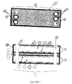
- FIG. 1 is a cross sectional and top view of one embodiment of a fuel cell cassette of the present invention.
- FIG. 2 is a cross sectional view of a second embodiment of the fuel cell cassette of the present invention.
- FIG. 3 is a cross sectional view of a third embodiment of the fuel cell cassette of the present invention.
- FIG. 4 is a cross sectional view of yet another embodiment of the fuel cell cassette of the present invention.
- FIG. 5 is a top view of a MEA for use in the present invention wherein each manifold port has been bonded about its perimeter.
- FIG. 6 is a cross sectional view of a port-seal fixture used in the manufacturing of the present invention which contains an assembly of MEAs and spacer films.
- FIG. 7 is a cross sectional view and top view of the edge encapsulation fixture used in the manufacturing of the present invention which contains a fuel cell cassette assembly design.
- FIG. 8 is a cross sectional view of a fuel cell stack which is comprised of fuel cell cassettes of the present invention with the addition of end plates and a compression means.
- FIG. 9 is a cross sectional and top view of fuel cell cassettes of the present invention wherein the fuel cell cassettes are contained within two sealed housing pieces for use as a typical fuel cell stack.
- the fuel cell cassette 1 shown comprises two unit cells 7 , each unit cell having a separator plate 6 , a fuel flow field 3 , a MEA 2 , and an oxidant flow field 4 .
- a coolant flow field 5 is sandwiched between the two unit cells 7 , with the addition of separator plates 6 , to provide cooling capability to the fuel cell cassette.
- the fuel cell cassette 1 is shown in its present configuration to facilitate the illustration of the present invention.
- an individual fuel cell cassette may embody various assemblies of MEAs, flow field plates and separator plates, as well as other fuel cell components to form unit cells within the fuel cell cassette and also that each such unit cell may be repeated or combined with different unit cells, dependent upon the power output, humidification and/or cooling requirements for the completed fuel cell cassette.
- FIG. 2 shows a fuel cell cassette 1 wherein the assembly for one unit cell 7 consists of (in this order): a separator plate 6 , a fuel flow field 3 , a MEA 2 , and an oxidant flow field 4 .
- a bipolar fuel cell arrangement This is referred in the art as a “bipolar fuel cell arrangement”.
- the bipolar fuel cell arrangement unit cell 7 is repeated more than once to illustrate that more than one unit cell 7 may be repeated, but unlike the assembly shown in FIG. 1 , no coolant flow field is employed.
- the unit cell 7 will normally be repeated more times than shown in FIG. 2 , since each additional unit cell 7 results in increased voltage output for the fuel cell cassette 1 .
- FIG. 3 shows a fuel cell cassette 1 having only one unit cell.
- a lower voltage fuel cell cassette 1 assembly may consist of only a fuel flow field 3 , a MEA 2 , and an oxidant flow field 4 .
- FIG. 4 shows another variation of a fuel cell cassette 1 assembly, which may be referred to as an “edge collection arrangement” (also known as a parallel or non-bipolar stack).
- a unit cell 8 consists of (in this order): a fuel flow field 3 , a MEA 2 , an oxidant flow field 4 , and another MEA 2 .
- Two edge collection arrangement unit cells 8 are shown in FIG. 4 , but as explained above, the unit cell 8 may be repeated as many times as necessary in the fuel cell cassette 1 to increase the current by the desired amount.
- FIG. 4 shows an edge collection arrangement without a coolant flow field, however, a coolant flow field may be added by placing a separator plate, a coolant flow field, and another separator plate between any pair of fuel/oxidant flow fields.
- coolant flow fields may cool each unit cell, or none of them, depending upon the cassette design.
- the reactant flow fields may be contained on a bipolar plate and not as separate layers. Any useful combination of the typical fuel cell component layers known to those skilled in the art may be used as the assembly for a fuel cell cassette of the present invention.
- the MEA 2 may be purchased from commercial suppliers or otherwise may be made in accordance with various methods of manufacturing known in the art, such as those methods described in U.S. Pat. No. 5,330,860 to Grot et al; U.S. Pat. No. 5,316,871 to Swathirajan et al., and U.S. Pat. No. 5,211,984 to Wilson.
- the anode side and cathode side, each on opposing faces of the membrane comprise either finely divided catalyst particles, such as platinum or its alloys, or finely divided carbon particles having the catalyst on its surfaces.
- the catalyst particles or catalyst-bearing carbon particles are dispersed throughout a polymeric binder or matrix that typically comprises either a proton conductive polymer and/or a fluoropolymer.
- the MEA 2 is constructed using a decal process wherein the catalyst ink is coated, painted, sprayed or screen-printed onto Teflon® or Kapton® blanks (both available commercially from E.I. duPont de Nemours and Company, U.S.A.), and the resulting decal is then transferred from the blank to the membrane surface and bonded, typically through the application of heat and pressure.
- a MEA 2 is fabricated wherein electrodes are coated with a catalyst containing a precious metal.
- finely distributed platinum is deposited onto specially treated carbon mats, at about 0.05 to about 10 milligrams of platinum per square centimeter, and a PEM is hot pressed between two such carbon mats with the coated side of the mats in contact with the membrane.
- PEMs useful in these MEAs include perfluorinated sulfonic acid membranes, such as Nafion® (available commercially from E.I. duPont de Nemours and Company, U.S.A.), Gore-Select® (available commercially from W.L.
- the MEA 2 of the present invention includes one or more manifold openings 9 through its thickness of the MEA 2 to allow for fuel, oxidant and, if required, coolant access into the fuel cell cassette 1 .
- manifold openings 9 may be punch cut into the MEA 2 through the use of a die, laser cut into the MEA 2 , or shaped by other suitable methods-known in the art.
- the number and size of the openings 9 may vary and are dependent upon the design of the fuel cell cassette 1 and the shape and diameter of the access manifolds needed for the distribution of reactants and coolants into the fuel cell cassette.
- manifold openings 9 are circular in shape, but the openings 9 may be formed in any geometric shape without limiting the usefulness of the methods described herein.
- the MEA 2 has a total of six circular manifold openings 9 —two for fuel access, two for oxidant access and two for coolant access.
- openings 9 are dependent upon the specific assembly design. being utilized for the fuel cell cassette 1 .
- each manifold opening 9 of the MEA 2 is bonded about its perimeter by a sealant to enable gas and liquid distribution throughout the fuel cell cassette 1 to be controlled by the flow fields and to prevent leakage of the reactants from the manifold openings 9 into the MEA 2 .
- FIG. 5 shows a MEA 2 having each manifold opening bonded about its perimeter 10 .
- the fuel flow field 3 , the oxidant flow field 4 , and the coolant flow field 5 may be purchased from commercial suppliers or otherwise may be made in accordance with various methods of manufacturing known in the art.
- laser cut stainless steel screens are employed for use as these fields.
- graphite, titanium or any corrosion resistant alloy may also be used.
- one or more of the flow fields are comprised of composite polymeric/graphite materials.
- Each flow field includes the same number of manifold openings 9 through its thickness as the number of manifold openings 9 included on the MEA 2 .
- separator plate 6 should be thin, lightweight, durable, electrically conductive and corrosion resistant.
- stainless steel is used for the separator plate 6 .
- graphite, titanium or any corrosion resistant alloy may also be used.
- one or more of the separator plates 6 could be fashioned from composite polymeric/graphite materials.
- Perimeter bonding 10 of specific manifold openings 9 of the porous components of the fuel cell cassette 1 is accomplished through the use of a pressure differential which allows the sealant to be drawn into and impregnated within the interstices of the porous component surrounding the manifold opening 9 .
- the pressure differential is accomplished by vacuum assisted resin transfer molding.
- the porous components include the GDL of the MEA 2 and the fuel, oxidant and coolant flow fields 3 , 4 and 5 , but the separator plates 6 are non-porous and do not require bonding about the perimeter of any manifold openings.
- Other fuel cell cassette designs known to those skilled in the art may include other porous components which may also be bonded through the use of the process described herein.
- the vacuum assisted resin transfer molding process for such perimeter bonding 10 is accomplished by first cutting a non-porous polymeric spacer film 16 with the same manifold opening configuration as the MEA 2 . If more than one MEA 2 is being bonded at one time, then the MEAs 2 and spacer films 16 are stacked, one on top of the other, with the manifold openings 9 of the MEAs 2 and the spacer films 16 aligned to form a MEA/spacer film assembly 11 . The MEA/spacer film assembly 11 is then placed into a port-seal-fixture (“PSF”) 12 as shown in FIG. 6 .
- PSF port-seal-fixture
- the port-seal-fixture 12 consists of a mold 13 , top seal/compression plate 14 , bolts 15 and vacuum holes 27 .
- the number and location of manifold openings in each MEA component are as shown in FIG. 1 such that six manifold channels 29 are formed in the MEA/spacer film assembly.
- Bolts 15 are then placed through the four corner manifold channels 29 of the MEA/spacer film assembly 11 to act as a compression means and also to seal the MEA/spacer film assembly 11 against any sealant flow in the direction perpendicular to the surface of the MEAs 2 .
- any compression means which is capable of uniformly distributing the load over the entire surface of the MEA/spacer film assembly 11 may be employed as the compression means, including external press, bolting, or banding.
- bonding of the manifold openings 9 may commence.
- a free-flowing resin is introduced into the entire volume of each opening 9 .
- the vacuum holes 27 are used, with the appropriate fittings, to pull a vacuum on the MEA/spacer film assembly 11 for a preset time such that the resin is drawn into each MEA 2 of the MEA/spacer film assembly 11 and is impregnated within each MEA 2 at the perimeter of the manifold openings 9 being bonded.
- the vacuum is confined to the edges of the MEA/spacer film assembly 11 by adding an additional non-porous polymer spacer film 16 layer on the top and bottom of the assembly 11 in combination with an O-ring gasket seal 26 in the top compression plate 14 as a sealing means.
- the sealant utilized to bond the perimeter of the manifold openings 9 is selected such that it is free-flowing and fills the void spaces.
- the sealant must also be chosen with regard to the chemical and mechanical properties required for the conditions encountered in an operating fuel cell system. For example, the sealant must be non-reactive with the reactants and byproducts within the fuel cell system and must be able withstand the operating temperature of the fuel cell system. Further, the sealant must not shrink or release more than minimal amounts of solvent into the fuel cell system.
- thermoplastic sealants useful in the present invention include both thermoplastics and thermoset elastomers.
- Preferred thermoplastic sealants include, but are not limited to, thermoplastic olefin elastomers, such as Santoprene® (available commercially from Advanced Elastomer Systems, L.P., U.S.A.), thermoplastic polyurethanes or plastomers, such as Exact® (available commercially from The Exxon Corporation, U.S.A.), polypropylene, polyethylene, polytetrafluoroethylene, fluorinated polypropylene, and polystyrene.
- thermoplastic olefin elastomers such as Santoprene® (available commercially from Advanced Elastomer Systems, L.P., U.S.A.)
- Exact® available commercially from The Exxon Corporation, U.S.A.
- polypropylene polyethylene
- polytetrafluoroethylene fluorinated polypropylene
- thermoset elastomer sealants include, but are not limited to, epoxy resins, such as 9223-2 (available commercially from the Minnesota Mining and Manufacturing Company, U.S.A.) and AY105/HY991 (available commercially from Ciba Specialty Chemical Corporation, U.S.A.), PUR resin such as Araldite®2018 (available commercially from Ciba Specialty Chemical Corporation, U.S.A), ALIPS resin such as FEC2234 (available commercially from Morton International, Inc., U.S.A.), SYLGARD® 170 A/B (available commercially from Dow Corning Corporation, U.S.A.), Fluorel® resin (available commercially from the Minnesota Mining and Manufacturing Company, U.S.A.), Fluorolast® resin (available commercially from Lauren International, Inc, U.S.A.), urethanes, silicones, fluorosilicones, and vinyl esters.
- epoxy resins such as 9223-2 (available commercially from the Minnesota Mining and Manufacturing Company, U.S
- manifold openings 9 must also be bonded on the various porous components to be utilized in the fuel cell cassette 1 , such as the flow fields 3 , 4 , and 5 , in order to control gas and liquid distributed throughout the fuel cell cassette 1 .
- the MEA 2 requires all manifold openings 9 to be bonded 10 as distribution of fuel/oxidant into the stack occurs through the reactant flow fields 3 and 4 .
- each flow field 3 , 4 , and 5 requires distribution of a reactant or coolant into the flow field, and it is desirable to prevent leakage of such reactant or coolant to the incorrect flow field.
- the manifold openings 9 from which oxygen (pure or in air) will enter the fuel cell cassette 1 must remain open to allow for diffision of the oxidant across the MEA 2 .
- These porous components may have additional manifold openings 9 to allow for manifold access through the fuel cell cassette 1 for distribution to other flow fields and these remaining manifold openings 9 must be bonded to prevent the diffusion of gas or coolant into the incorrect flow field. Therefore, each flow field 3 , 4 , and 5 will have different positioning of bonded and unbonded manifold openings 9 .
- the final fuel cell cassette 1 design assembly consists of the following components (in the following order): a separator plate 6 , a fuel flow field 3 , a MEA 2 , and oxidant flow field 4 , a separator plate 6 , a coolant flow field 5 , a separator plate 6 , a fuel flow field 3 , a MEA 2 , an oxidant flow field 4 , and a separator plate 6 .
- the final fuel cell cassette design assembly is formed such that all components are assembled relative to each other to form a stacked formation having the manifold openings 9 located on each component aligned with the manifold openings 9 located on the other components to define a plurality of manifold channels 29 extending through the thickness of the fuel cell cassette assembly. If other assembly designs are utilized, such as those shown in FIG. 2 and FIG. 3 , the components would be aligned in the same manner.
- Each of the components of the fuel cell cassette design assembly is bonded along its peripheral edges 18 with the other components in the fuel cell cassette design assembly in order to form the completed fuel cell cassette 1 of the present invention, such that the fuel cell cassette 1 has a fully encapsulated edge periphery 18 to separate the fuel cell cassette components from the outside environment thereby preventing membrane dry out on exposure to the ambient and to provide structural support for the fuel cell cassette 1 .
- the peripheral edge encapsulation is conducted through the use of a pressure differential which draws the resin into the interstices of any porous components and within the spaces separating one component from the other and impregnates the resin there between.
- the pressure differential is accomplished through vacuum assisted resin transfer molding.
- a piece of non-porous polymeric spacer 16 film is placed on both the top and bottom sides of the final design assembly for the fuel cell cassette 1 in order to cap the assembly.
- the cassette/film assembly 20 is then placed into the edge encapsulation fixture (“EEF”) 19 , as shown in FIG. 7 .
- the EEF 19 consists of a mold 30 , top seal/vacuum plate 21 , vacuum fittings 31 to the manifold channels 29 and a compression means.
- the top seal/vacuum plate 21 serves two functions: It evenly distributes the load to the cassette/film assembly 20 and contains fittings 31 to uniformly introduce vacuum to each manifold channel 29 .
- the compression means is required to insure that the flowable resin fully encapsulates the non-porous components while using the minimum amount of resin 17 .
- a number of techniques can be used to supply the required load and compression means, including an external press, bolting, or banding.
- a guide mechanism is used to ensure that the top sea/vacuum plate 21 remains perpendicular to the base of the EEF 19 .
- a compressive load is first applied to the cassette/film assembly 20 using torque bolts 15 or a hand press.
- a free-flowing resin 17 is poured into the mold 30 , outside the periphery of the cassette/film assembly 20 .
- Any resin 17 useful for the perimeter bonding of the manifold openings 9 of the porous components may be used for the encapsulation of the periphery of the fuel cell cassette 1 .
- a vacuum is applied to the EEF 19 through the vacuum fittings 31 . The compressive load insures that the vacuum is pulled only in the manifold openings 9 via the manifold channels 29 .
- the resin 17 flows into the outer edges of the fuel cell cassette/film assembly 20 , thereby encapsulating the peripheral edges of the porous and non-porous components of the fuel cell cassette 1 .
- This provides a secondary seal for all flow fields and other porous components by separating the entire fuel cell cassette 1 periphery from the outside environment while also preventing the edges of all such porous components from drying out on exposure to the ambient environment.
- the encapsulated periphery 18 provides structural support for the fuel cell cassette 1 and a surface area on the resulting fuel cell cassette 1 on which the fittings and other hardware needed for reactant, coolant, and current distribution can be fixed.
- the resin 17 is allowed to sit within the mold 30 of the EEF 19 and solidify. Once hardening is complete, the top seal/vacuum plate 21 is removed, followed by the removal of the non-porous film 16 layer from each side of the fuel cell cassette 1 . The top and bottom edge of the fuel cell cassette 1 may then be trimmed and the edges routed to remove any excess resin.
- FIG. 8 a fuel cell stack 22 comprising two fuel cell cassettes 1 of the present invention is shown.
- endplates 23 and further compression means, such as bolts 15 have been added to insure contact within the fuel cell stack 22 .
- the endplates 23 are heavy metallic structures, with internal channels for the flow of reactants and coolant, as well as bolts 15 and gaskets for compression.
- a number of endplate configurations are known to those skilled in the art.
- a fuel cell stack 22 comprising two fuel cell cassettes 1
- any other number of fuel cell cassettes 1 may be utilized in the fuel cell stack 22 depending upon final output requirements of the fuel cell system. If lower output requirements are sufficient, a fuel cell stack 22 may consist of only one fuel cell cassette 1 with the addition of endplates 23 or other compression means. If more than one fuel cell cassette 1 is utilized for the fuel cell stack 22 , each fuel cell cassette 1 must be stacked such that the manifold openings 9 of all the fuel cell cassettes 1 are aligned to form manifold channels 29 extending through the fuel cell stack 22 .
- a fuel cell stack 22 may be manufactured in which the fuel cell cassettes 1 of the present invention are contained within two housing pieces 24 as shown in FIG. 9 .
- This embodiment eliminates much of the expensive and bulky hardware needed for the compression means in the fuel cell stack 22 shown in FIG. 8 as the endplates 23 and bolts 15 are no longer required.
- the housing pieces 24 may be formed of metal, thermosets, or traditional engineering thermoplastics.
- Preferred thermoplastics include polyether sulfones, polyphenylene sulfones, polyphenylene sulfide, polysulfone, polyphenylene oxide, polyphenylene ether, polypropylene, polyethylene, polytetrafluoroethylene, and fluorinated polypropylene, or blends thereof.
- the thermoplastic material may contain a filler material, such as glass fibers, graphite fibers, aramid fibers, ceramic fibers, silica, talc, calcium carbonate, silicon carbide, graphite powder, boron nitride, polytetrafluoroethylene, and metal powders or fibers.
- the housing pieces are formed from a glass fiber filled polysulfone.
- Preferred thermosets include epoxies or polyurethanes.
- FIG. 9 one preferred embodiment of a fuel cell stack 22 is shown which comprises a first housing piece 24 having a base opening and a sidewall opening extending from the base opening to define a first storage compartment and having at least one reactant manifold opening 9 extending through the thickness of the base opening.
- a second housing piece 24 is shown having a top opening and a sidewall opening extending from the top opening to define a second storage compartment and further having at least one reactant manifold opening 9 extending through the thickness of the top opening.
- One or more fuel cell cassettes 1 of the present invention are placed within the storage compartment of the base portion of the first housing piece 24 .
- the fuel cassettes 1 must be stacked such that the manifold openings 9 of all the fuel cell cassettes 1 are aligned.
- the top portion of the second housing piece 24 may then be placed such that the sidewall portion of the second housing piece 24 is resting on the sidewall portion of the first housing piece 24 . If both first and second housing pieces 24 contain manifold openings 9 , such as shown in the embodiment of FIG.
- the reactant manifold openings 9 of the first housing piece 24 are aligned with the manifold openings 9 of the second housing piece 24 and the manifold openings 9 of the fuel cell cassettes 1 to form manifold channels 29 through the thickness of the fuel cell stack 22 and both housing pieces 24 .
- only one of the housing pieces 24 may contain manifold openings 9 and the manifold channels 29 may only extend through the fuel cell cassettes 1 and one of the housing pieces 24 .
- the two housing pieces 24 may be joined, preferably by means of a sealant, although bolts or other mechanical means of joining may be used.
- sealing is accomplished by first applying a compression means to the two housing pieces 24 .
- the compression means may be a platen press, fasteners or other compression means known in the art.
- a sealant is then injected by an injection molding process at the interface of the sidewall portions of the first and second housing pieces 24 .
- the sealant is selected with regard to the chemical and mechanical properties required for the conditions encountered in an operating fuel cell system, such as the ability to withstand the operating temperatures within such fuel cell system.
- the sealant is polypropylene, but other polymer sealants known in the art, such as urethanes or epoxies may also be used.
- Sealants which may be used also include, but are not limited to, PUR resin such as Araldite®2018 (available commercially from Ciba Specialty Chemical Corporation, U.S.A.), ALIPS resin such as FEC2234 (available commercially from Morton International, Inc., U.S.A.), SYLGARD® 170 A/B (available commercially from Dow Corning Corporation, U.S.A.), Fluorel® resin (available commercially from the Minnesota Mining and Manufacturing Company, U.S.A.), Fluorolast® resin (available commercially from Lauren International, Inc, U.S.A.), silicones, fluorosilicones, and vinyl esters.
- PUR resin such as Araldite®2018 (available commercially from Ciba Specialty Chemical Corporation, U.S.A.)
- ALIPS resin such as FEC2234 (available commercially from Morton International, Inc., U.S.A.), SYLGARD® 170 A/B (available commercially from Dow Corning Corporation, U.S.A.
- the compression means is removed as compression for the fuel cell stack 22 is now inherently provided by the two sealed housing pieces 24 .
- a fuel cell stack 22 formation comprised of fuel cell cassettes 1 of the present invention is thereby encased within the storage compartments of the two joined housing pieces 24 while reactant access to the fuel cell stack 22 is provided through the manifold channels 29 .
Abstract
Description
Claims (9)
Priority Applications (1)
| Application Number | Priority Date | Filing Date | Title |
|---|---|---|---|
| US11/229,087 US7482086B2 (en) | 2000-11-27 | 2005-09-16 | Electrochemical polymer electrolyte membrane cell stacks and manufacturing methods thereof |
Applications Claiming Priority (3)
| Application Number | Priority Date | Filing Date | Title |
|---|---|---|---|
| US25319900P | 2000-11-27 | 2000-11-27 | |
| US09/908,359 US6946210B2 (en) | 2000-11-27 | 2001-07-18 | Electrochemical polymer electrolyte membrane cell stacks and manufacturing methods thereof |
| US11/229,087 US7482086B2 (en) | 2000-11-27 | 2005-09-16 | Electrochemical polymer electrolyte membrane cell stacks and manufacturing methods thereof |
Related Parent Applications (1)
| Application Number | Title | Priority Date | Filing Date |
|---|---|---|---|
| US09/908,359 Division US6946210B2 (en) | 2000-11-27 | 2001-07-18 | Electrochemical polymer electrolyte membrane cell stacks and manufacturing methods thereof |
Publications (2)
| Publication Number | Publication Date |
|---|---|
| US20060024545A1 US20060024545A1 (en) | 2006-02-02 |
| US7482086B2 true US7482086B2 (en) | 2009-01-27 |
Family
ID=26943016
Family Applications (2)
| Application Number | Title | Priority Date | Filing Date |
|---|---|---|---|
| US09/908,359 Expired - Lifetime US6946210B2 (en) | 2000-11-27 | 2001-07-18 | Electrochemical polymer electrolyte membrane cell stacks and manufacturing methods thereof |
| US11/229,087 Expired - Lifetime US7482086B2 (en) | 2000-11-27 | 2005-09-16 | Electrochemical polymer electrolyte membrane cell stacks and manufacturing methods thereof |
Family Applications Before (1)
| Application Number | Title | Priority Date | Filing Date |
|---|---|---|---|
| US09/908,359 Expired - Lifetime US6946210B2 (en) | 2000-11-27 | 2001-07-18 | Electrochemical polymer electrolyte membrane cell stacks and manufacturing methods thereof |
Country Status (8)
| Country | Link |
|---|---|
| US (2) | US6946210B2 (en) |
| EP (1) | EP1356532B1 (en) |
| JP (1) | JP4346905B2 (en) |
| AT (1) | ATE426252T1 (en) |
| AU (1) | AU2002217974A1 (en) |
| CA (1) | CA2430083C (en) |
| DE (1) | DE60138045D1 (en) |
| WO (1) | WO2002043173A1 (en) |
Families Citing this family (51)
| Publication number | Priority date | Publication date | Assignee | Title |
|---|---|---|---|---|
| US6946210B2 (en) * | 2000-11-27 | 2005-09-20 | Protonex Technology Corporation | Electrochemical polymer electrolyte membrane cell stacks and manufacturing methods thereof |
| US20050095492A1 (en) * | 2001-05-15 | 2005-05-05 | Hydrogenics Corporation | Fuel cell stack |
| US6852439B2 (en) | 2001-05-15 | 2005-02-08 | Hydrogenics Corporation | Apparatus for and method of forming seals in fuel cells and fuel cell stacks |
| US6821666B2 (en) * | 2001-09-28 | 2004-11-23 | The Regents Of The Univerosity Of California | Method of forming a package for mems-based fuel cell |
| US7306864B2 (en) | 2001-10-22 | 2007-12-11 | Protonex Technology Corporation | One-shot fabrication of membrane-based electrochemical cell stacks |
| US6805990B2 (en) * | 2001-10-24 | 2004-10-19 | Fuelcell Energy, Ltd. | Flat plate fuel cell stack |
| DE10160905B4 (en) * | 2001-12-12 | 2007-07-19 | Carl Freudenberg Kg | Sealing arrangement for fuel cells, method for producing and using such a sealing arrangement |
| US7687181B2 (en) * | 2002-04-23 | 2010-03-30 | Protonex Technology Corporation | Channel-based electrochemical cassettes |
| EP1573846A2 (en) * | 2002-09-23 | 2005-09-14 | Protonex Technology Corporation | Liquid electrochemical cell stacks and manufacturing methods for same |
| JP4067371B2 (en) | 2002-09-25 | 2008-03-26 | 本田技研工業株式会社 | Fuel cell |
| JP4799866B2 (en) * | 2002-11-18 | 2011-10-26 | プロトネクス テクノロジー コーポレーション | Membrane-based electrochemical cell stack |
| AU2003294579A1 (en) * | 2002-12-04 | 2004-06-23 | Lynntech Power Systems, Ltd | Adhesively bonded electrochemical cell stacks |
| CA2516765C (en) * | 2003-02-27 | 2012-05-01 | Protonex Technology Corporation | Externally manifolded membrane based electrochemical cell stacks |
| US20050048349A1 (en) * | 2003-08-28 | 2005-03-03 | Fannon Megan A. | Method of manufacturing a fuel cell array and a related array |
| US7297269B2 (en) * | 2003-10-31 | 2007-11-20 | Protonex Technology Corporation | Cross-flow filtration cassettes and methods for fabrication of same |
| US8758958B2 (en) | 2004-12-29 | 2014-06-24 | Clearedge Power, Llc | Fuel cell separator plate assembly |
| US20080057373A1 (en) * | 2004-12-29 | 2008-03-06 | Utc Power Corporation | Fuel Cell Separator Plate Assembly |
| US20070212587A1 (en) * | 2005-04-01 | 2007-09-13 | Nick Fragiadakis | Apparatus for and method of forming seals in an electrochemical cell assembly |
| NO20053220D0 (en) * | 2005-06-29 | 2005-06-29 | Norsk Hydro As | Compression of a PEM cell stack in a pressure tank. |
| US7914943B2 (en) * | 2005-08-19 | 2011-03-29 | Daimler Ag | Integrated seal for fuel cell assembly and fuel cell stack |
| US20070048580A1 (en) * | 2005-08-30 | 2007-03-01 | Cheng-Hsin Chen | Fuel cell |
| DE502005004821D1 (en) * | 2005-09-06 | 2008-09-04 | Sgl Carbon Ag | Electrodes for fuel cells |
| EP2266682A3 (en) * | 2005-09-09 | 2014-08-20 | Tangenx Technology Corporation | Laminated cassette device and method for making same |
| FR2891950B1 (en) * | 2005-10-11 | 2014-05-30 | Commissariat Energie Atomique | FUEL CELL SEALED STACK |
| ATE511912T1 (en) * | 2005-12-20 | 2011-06-15 | Tangenx Technology Corp | FILTRATION ARRANGEMENT AND METHOD FOR THE PRODUCTION AND USE THEREOF |
| US7879507B2 (en) * | 2006-04-10 | 2011-02-01 | Protonex Technology Corporation | Insert-molded, externally manifolded, one-shot sealed membrane based electrochemical cell stacks |
| KR100821033B1 (en) | 2007-04-12 | 2008-04-08 | 삼성에스디아이 주식회사 | Fuel cell stack and manufacturing method thereof |
| US8124292B2 (en) * | 2007-06-28 | 2012-02-28 | Protonex Technology Corporation | Fuel cell stacks and methods |
| US8580457B2 (en) * | 2007-06-28 | 2013-11-12 | Protonex Technology Corporation | Fuel cell stack sealed with encapsulating material and method of making the same |
| US20090123784A1 (en) * | 2007-09-13 | 2009-05-14 | Pavlik Thomas J | Fuel cell module |
| KR101274893B1 (en) * | 2008-08-05 | 2013-06-14 | 주식회사 엘지화학 | Stack and folding-typed electrode assembly and electrochemical cell comprising the Same |
| US8236067B2 (en) * | 2008-08-11 | 2012-08-07 | GM Global Technology Operations LLC | Method and apparatus for fuel cell stack assembly |
| US20110171562A1 (en) * | 2010-01-08 | 2011-07-14 | Gm Global Technology Operations, Inc. | Process for forming a membrane-subgasket assembly using vacuum sealing |
| US20110229790A1 (en) * | 2010-03-19 | 2011-09-22 | Kenji Sato | Fuel cell module and fuel cell stack |
| CN101826620B (en) * | 2010-03-30 | 2014-08-13 | 上海恒劲动力科技有限公司 | Bipolar plate for fuel cells |
| KR20120105331A (en) * | 2011-03-15 | 2012-09-25 | 현대자동차주식회사 | Fuel cell stack with improved corrosion-resistance |
| JP2013004352A (en) * | 2011-06-17 | 2013-01-07 | Toyota Motor Corp | Fuel cell system |
| CN103915631B (en) * | 2012-12-31 | 2018-04-24 | 上海恒劲动力科技有限公司 | A kind of air-cooled integrated bipolar plates of fuel cell |
| US10096844B2 (en) | 2013-10-03 | 2018-10-09 | Hamilton Sundstrand Corporation | Manifold for plural fuel cell stacks |
| EP3455892B1 (en) | 2016-05-13 | 2024-02-07 | QuantumScape Battery, Inc. | Solid electrolyte separator bonding agent |
| DE102016221998A1 (en) * | 2016-11-09 | 2018-05-09 | Bayerische Motoren Werke Aktiengesellschaft | Method for producing a fuel cell stack |
| US20180212259A1 (en) | 2017-01-23 | 2018-07-26 | GM Global Technology Operations LLC | Fuel cell microseal and a method of manufacture thereof |
| AU2018229330B2 (en) * | 2017-03-01 | 2023-07-27 | Axine Water Technologies Inc. | Stack of electrochemical cells for wastewater treatment with isolated electrodes |
| US20200395584A1 (en) * | 2017-11-28 | 2020-12-17 | Quantumscape Corporation | Catholyte management for a solid-state separator |
| EP3740988A1 (en) * | 2018-01-17 | 2020-11-25 | Nuvera Fuel Cells, LLC | Electrochemical cells with improved fluid flow design |
| IL259978B (en) * | 2018-06-12 | 2020-07-30 | Pocell Tech Ltd | Alkaline membrane fuel cell assembly comprising a thin membrane and method of making same |
| DE102018212715A1 (en) * | 2018-07-31 | 2020-02-06 | Robert Bosch Gmbh | Fuel cell stack and method for producing a fuel cell stack |
| DE102018213912A1 (en) * | 2018-08-17 | 2020-02-20 | Audi Ag | Fuel cell device and method for monitoring and structural adaptation of a fuel cell device |
| FR3102308B1 (en) * | 2019-10-18 | 2022-06-03 | Air Liquide | Fuel cell bipolar plate |
| KR20210049339A (en) * | 2019-10-25 | 2021-05-06 | 현대자동차주식회사 | Fuel cell |
| EP4309228A2 (en) | 2021-09-27 | 2024-01-24 | QuantumScape Battery, Inc. | Electrochemical stack and method of assembly thereof |
Citations (23)
| Publication number | Priority date | Publication date | Assignee | Title |
|---|---|---|---|---|
| US3846176A (en) | 1969-01-18 | 1974-11-05 | Siemens Ag | Fuel cell encased in molded plastic material |
| US4397917A (en) | 1982-01-11 | 1983-08-09 | Energy Research Corporation | Fuel cell pack with internal connection of fuel cells |
| EP0122150A2 (en) | 1983-04-11 | 1984-10-17 | Engelhard Corporation | Integral gas seal for fuel cell gas distribution assemblies and method of fabrication |
| US4604331A (en) | 1984-05-29 | 1986-08-05 | The United States Of America As Represented By The United States Department Of Energy | Fuel cell separator plate with bellows-type sealing flanges |
| US5110691A (en) | 1991-01-16 | 1992-05-05 | International Fuel Cells Corporation | Fuel cell component sealant |
| US5176966A (en) | 1990-11-19 | 1993-01-05 | Ballard Power Systems Inc. | Fuel cell membrane electrode and seal assembly |
| US5264299A (en) | 1991-12-26 | 1993-11-23 | International Fuel Cells Corporation | Proton exchange membrane fuel cell support plate and an assembly including the same |
| US5453331A (en) | 1994-08-12 | 1995-09-26 | University Of Chicago | Compliant sealants for solid oxide fuel cells and other ceramics |
| US5523175A (en) | 1991-12-26 | 1996-06-04 | International Fuel Cells Corporation | Plate-shaped fuel cell component |
| WO1998033225A1 (en) | 1997-01-29 | 1998-07-30 | Magnet-Motor Gesellschaft Für Magnetmotorische Technik Mbh | Membrane-electrode unit with an integrated wear ring, and production process |
| US5858569A (en) | 1997-03-21 | 1999-01-12 | Plug Power L.L.C. | Low cost fuel cell stack design |
| EP0951086A2 (en) | 1998-04-17 | 1999-10-20 | Matsushita Electric Industrial Co., Ltd. | Solid polymer electrolyte fuel cell and method for producing the same |
| US6042955A (en) | 1995-05-25 | 2000-03-28 | Honda Giken Kogyo Kabushiki Kaisha | Fuel cell and method of controlling same |
| US6057054A (en) | 1997-07-16 | 2000-05-02 | Ballard Power Systems Inc. | Membrane electrode assembly for an electrochemical fuel cell and a method of making an improved membrane electrode assembly |
| US6080503A (en) | 1997-03-29 | 2000-06-27 | Ballard Power Systems Inc. | Polymer electrolyte membrane fuel cells and stacks with adhesively bonded layers |
| US6159628A (en) | 1998-10-21 | 2000-12-12 | International Fuel Cells Llc | Use of thermoplastic films to create seals and bond PEM cell components |
| US6165634A (en) | 1998-10-21 | 2000-12-26 | International Fuel Cells Llc | Fuel cell with improved sealing between individual membrane assemblies and plate assemblies |
| US20010001052A1 (en) | 1998-12-23 | 2001-05-10 | Bonk Stanley P. | Fuel cell stack assembly with edge seal |
| US6372372B1 (en) * | 2000-02-11 | 2002-04-16 | Plug Power Inc. | Clamping system for a fuel cell stack |
| WO2002093668A1 (en) | 2001-05-15 | 2002-11-21 | Hydrogenics Corporation | Flow field plate for a fuel cell and fuel cell assembly incorporating the flow field plate |
| WO2002093672A2 (en) | 2001-05-15 | 2002-11-21 | Hydrogenics Corporation | Method of forming seals in fuel cells and fuel cell stacks |
| US20030096153A1 (en) | 2001-10-22 | 2003-05-22 | Paul Osenar | One-shot fabrication of membrane-based electrochemical cell stacks |
| US6596427B1 (en) | 2000-11-06 | 2003-07-22 | Ballard Power Systems Inc. | Encapsulating seals for electrochemical cell stacks and methods of sealing electrochemical cell stacks |
Family Cites Families (2)
| Publication number | Priority date | Publication date | Assignee | Title |
|---|---|---|---|---|
| JPH0260063A (en) * | 1988-08-24 | 1990-02-28 | Meidensha Corp | Stacked fuel cell |
| US6946210B2 (en) * | 2000-11-27 | 2005-09-20 | Protonex Technology Corporation | Electrochemical polymer electrolyte membrane cell stacks and manufacturing methods thereof |
-
2001
- 2001-07-18 US US09/908,359 patent/US6946210B2/en not_active Expired - Lifetime
- 2001-11-27 JP JP2002544801A patent/JP4346905B2/en not_active Expired - Lifetime
- 2001-11-27 AT AT01997859T patent/ATE426252T1/en not_active IP Right Cessation
- 2001-11-27 CA CA2430083A patent/CA2430083C/en not_active Expired - Lifetime
- 2001-11-27 EP EP01997859A patent/EP1356532B1/en not_active Expired - Lifetime
- 2001-11-27 DE DE60138045T patent/DE60138045D1/en not_active Expired - Lifetime
- 2001-11-27 AU AU2002217974A patent/AU2002217974A1/en not_active Abandoned
- 2001-11-27 WO PCT/US2001/044880 patent/WO2002043173A1/en active Application Filing
-
2005
- 2005-09-16 US US11/229,087 patent/US7482086B2/en not_active Expired - Lifetime
Patent Citations (26)
| Publication number | Priority date | Publication date | Assignee | Title |
|---|---|---|---|---|
| US3846176A (en) | 1969-01-18 | 1974-11-05 | Siemens Ag | Fuel cell encased in molded plastic material |
| US4397917A (en) | 1982-01-11 | 1983-08-09 | Energy Research Corporation | Fuel cell pack with internal connection of fuel cells |
| EP0122150A2 (en) | 1983-04-11 | 1984-10-17 | Engelhard Corporation | Integral gas seal for fuel cell gas distribution assemblies and method of fabrication |
| US4604331A (en) | 1984-05-29 | 1986-08-05 | The United States Of America As Represented By The United States Department Of Energy | Fuel cell separator plate with bellows-type sealing flanges |
| US5176966A (en) | 1990-11-19 | 1993-01-05 | Ballard Power Systems Inc. | Fuel cell membrane electrode and seal assembly |
| US5110691A (en) | 1991-01-16 | 1992-05-05 | International Fuel Cells Corporation | Fuel cell component sealant |
| US5264299A (en) | 1991-12-26 | 1993-11-23 | International Fuel Cells Corporation | Proton exchange membrane fuel cell support plate and an assembly including the same |
| US5523175A (en) | 1991-12-26 | 1996-06-04 | International Fuel Cells Corporation | Plate-shaped fuel cell component |
| US5453331A (en) | 1994-08-12 | 1995-09-26 | University Of Chicago | Compliant sealants for solid oxide fuel cells and other ceramics |
| US6042955A (en) | 1995-05-25 | 2000-03-28 | Honda Giken Kogyo Kabushiki Kaisha | Fuel cell and method of controlling same |
| US6475656B1 (en) | 1997-01-29 | 2002-11-05 | Proton Motor Fuel Cell Gmbh | Membrane-electrode unit with an integrated wear ring, and method of making the same |
| WO1998033225A1 (en) | 1997-01-29 | 1998-07-30 | Magnet-Motor Gesellschaft Für Magnetmotorische Technik Mbh | Membrane-electrode unit with an integrated wear ring, and production process |
| US5858569A (en) | 1997-03-21 | 1999-01-12 | Plug Power L.L.C. | Low cost fuel cell stack design |
| US6080503A (en) | 1997-03-29 | 2000-06-27 | Ballard Power Systems Inc. | Polymer electrolyte membrane fuel cells and stacks with adhesively bonded layers |
| US6057054A (en) | 1997-07-16 | 2000-05-02 | Ballard Power Systems Inc. | Membrane electrode assembly for an electrochemical fuel cell and a method of making an improved membrane electrode assembly |
| EP0951086A2 (en) | 1998-04-17 | 1999-10-20 | Matsushita Electric Industrial Co., Ltd. | Solid polymer electrolyte fuel cell and method for producing the same |
| US6159628A (en) | 1998-10-21 | 2000-12-12 | International Fuel Cells Llc | Use of thermoplastic films to create seals and bond PEM cell components |
| US6165634A (en) | 1998-10-21 | 2000-12-26 | International Fuel Cells Llc | Fuel cell with improved sealing between individual membrane assemblies and plate assemblies |
| US20010001052A1 (en) | 1998-12-23 | 2001-05-10 | Bonk Stanley P. | Fuel cell stack assembly with edge seal |
| US6372372B1 (en) * | 2000-02-11 | 2002-04-16 | Plug Power Inc. | Clamping system for a fuel cell stack |
| US6596427B1 (en) | 2000-11-06 | 2003-07-22 | Ballard Power Systems Inc. | Encapsulating seals for electrochemical cell stacks and methods of sealing electrochemical cell stacks |
| WO2002093668A1 (en) | 2001-05-15 | 2002-11-21 | Hydrogenics Corporation | Flow field plate for a fuel cell and fuel cell assembly incorporating the flow field plate |
| US20020172852A1 (en) | 2001-05-15 | 2002-11-21 | David Frank | Flow field plate for a fuel cell and fuel cell assembly incorporating the flow field plate |
| WO2002093672A2 (en) | 2001-05-15 | 2002-11-21 | Hydrogenics Corporation | Method of forming seals in fuel cells and fuel cell stacks |
| US20030031914A1 (en) | 2001-05-15 | 2003-02-13 | Frank David G. | Apparatus for and method of forming seals in fuel cells and fuel cell stacks |
| US20030096153A1 (en) | 2001-10-22 | 2003-05-22 | Paul Osenar | One-shot fabrication of membrane-based electrochemical cell stacks |
Non-Patent Citations (1)
| Title |
|---|
| Patent Abstracts of Japan, vol. 014, No. 229, JP-02060063, "Stacked Fuel Cell" (1990). |
Also Published As
| Publication number | Publication date |
|---|---|
| CA2430083C (en) | 2010-11-09 |
| EP1356532A4 (en) | 2007-02-21 |
| ATE426252T1 (en) | 2009-04-15 |
| JP4346905B2 (en) | 2009-10-21 |
| US20020068212A1 (en) | 2002-06-06 |
| US6946210B2 (en) | 2005-09-20 |
| JP2004534350A (en) | 2004-11-11 |
| US20060024545A1 (en) | 2006-02-02 |
| EP1356532B1 (en) | 2009-03-18 |
| DE60138045D1 (en) | 2009-04-30 |
| CA2430083A1 (en) | 2002-05-30 |
| AU2002217974A1 (en) | 2002-06-03 |
| EP1356532A1 (en) | 2003-10-29 |
| WO2002043173A1 (en) | 2002-05-30 |
Similar Documents
| Publication | Publication Date | Title |
|---|---|---|
| US7482086B2 (en) | Electrochemical polymer electrolyte membrane cell stacks and manufacturing methods thereof | |
| CA2506592C (en) | Membrane electrode assembly with periphery gasket and sealing channels | |
| US8232015B2 (en) | One-shot fabrication of membrane based electrochemical cell stacks | |
| AU2005299831B8 (en) | Membrane based electrochemical cell stacks | |
| CA2516765C (en) | Externally manifolded membrane based electrochemical cell stacks | |
| US7879507B2 (en) | Insert-molded, externally manifolded, one-shot sealed membrane based electrochemical cell stacks | |
| EP1502313B1 (en) | Membrane based electrochemical cell stacks | |
| AU2003295710B2 (en) | Membrane based electrochemical cell stacks | |
| AU2002363067A1 (en) | One-shot fabrication of membrane-based electrochemical cell stacks |
Legal Events
| Date | Code | Title | Description |
|---|---|---|---|
| STCF | Information on status: patent grant |
Free format text: PATENTED CASE |
|
| FPAY | Fee payment |
Year of fee payment: 4 |
|
| AS | Assignment |
Owner name: WINDSAIL CAPITAL III, LLC, MASSACHUSETTS Free format text: SECURITY AGREEMENT;ASSIGNOR:PROTONEX TECHNOLOGY CORPORATION;REEL/FRAME:029964/0733 Effective date: 20130308 Owner name: SILICON VALLEY BANK, MASSACHUSETTS Free format text: ASSIGNMENT OF ASSIGNORS INTEREST;ASSIGNOR:PROTONEX TECHNOLOGY CORPORATION;REEL/FRAME:030062/0501 Effective date: 20130308 |
|
| AS | Assignment |
Owner name: SILICON VALLEY BANK, MASSACHUSETTS Free format text: SECURITY AGREEMENT;ASSIGNOR:PROTONEX TECHNOLOGY CORPORATION;REEL/FRAME:035748/0937 Effective date: 20150520 |
|
| AS | Assignment |
Owner name: PROTONEX TECHNOLOGY CORPORATION, MASSACHUSETTS Free format text: RELEASE BY SECURED PARTY;ASSIGNOR:SILICON VALLEY BANK;REEL/FRAME:036700/0203 Effective date: 20150924 |
|
| AS | Assignment |
Owner name: PROTONEX TECHNOLOGY CORPORATION, MASSACHUSETTS Free format text: RELEASE BY SECURED PARTY;ASSIGNOR:WINDSAIL CAPITAL III, LLC;REEL/FRAME:036742/0604 Effective date: 20151001 |
|
| FEPP | Fee payment procedure |
Free format text: PAT HOLDER NO LONGER CLAIMS SMALL ENTITY STATUS, ENTITY STATUS SET TO UNDISCOUNTED (ORIGINAL EVENT CODE: STOL); ENTITY STATUS OF PATENT OWNER: LARGE ENTITY |
|
| FPAY | Fee payment |
Year of fee payment: 8 |
|
| AS | Assignment |
Owner name: PROTONEX TECHNOLOGY CORPORATION, MASSACHUSETTS Free format text: ASSIGNMENT OF ASSIGNORS INTEREST;ASSIGNORS:OSENAR, PAUL;FORMATO, RICHARD M.;HERCZEG, ATTILA E.;AND OTHERS;SIGNING DATES FROM 20010705 TO 20010709;REEL/FRAME:049158/0655 |
|
| AS | Assignment |
Owner name: BALLARD UNMANNED SYSTEMS INC., MASSACHUSETTS Free format text: CHANGE OF NAME;ASSIGNOR:PROTONEX TECHNOLOGY CORPORATION;REEL/FRAME:049220/0063 Effective date: 20181121 |
|
| MAFP | Maintenance fee payment |
Free format text: PAYMENT OF MAINTENANCE FEE, 12TH YEAR, LARGE ENTITY (ORIGINAL EVENT CODE: M1553); ENTITY STATUS OF PATENT OWNER: LARGE ENTITY Year of fee payment: 12 |
|
| AS | Assignment |
Owner name: PARALLEL WIRELESS, INC., NEW HAMPSHIRE Free format text: RELEASE BY SECURED PARTY;ASSIGNORS:VENTURE LENDING & LEASING IX, INC.;WTI FUND X, INC.;REEL/FRAME:060900/0022 Effective date: 20220629 |