US7460120B2 - Map display apparatus - Google Patents
Map display apparatus Download PDFInfo
- Publication number
- US7460120B2 US7460120B2 US10/984,840 US98484004A US7460120B2 US 7460120 B2 US7460120 B2 US 7460120B2 US 98484004 A US98484004 A US 98484004A US 7460120 B2 US7460120 B2 US 7460120B2
- Authority
- US
- United States
- Prior art keywords
- coordinate
- correction
- view
- transformation matrix
- dimensional object
- Prior art date
- Legal status (The legal status is an assumption and is not a legal conclusion. Google has not performed a legal analysis and makes no representation as to the accuracy of the status listed.)
- Expired - Fee Related, expires
Links
Images


Classifications
-
- G—PHYSICS
- G01—MEASURING; TESTING
- G01C—MEASURING DISTANCES, LEVELS OR BEARINGS; SURVEYING; NAVIGATION; GYROSCOPIC INSTRUMENTS; PHOTOGRAMMETRY OR VIDEOGRAMMETRY
- G01C21/00—Navigation; Navigational instruments not provided for in groups G01C1/00 - G01C19/00
- G01C21/26—Navigation; Navigational instruments not provided for in groups G01C1/00 - G01C19/00 specially adapted for navigation in a road network
- G01C21/34—Route searching; Route guidance
- G01C21/36—Input/output arrangements for on-board computers
- G01C21/3626—Details of the output of route guidance instructions
- G01C21/3635—Guidance using 3D or perspective road maps
- G01C21/3638—Guidance using 3D or perspective road maps including 3D objects and buildings
Definitions
- the present invention relates to the map display apparatus which displays a map on a screen, in particular, to a map display apparatus which generates a three-dimensional image from the electronized map data, and displays a map on the screen.
- a map display apparatus which generates and displays a three-dimensional image from electronized map data has been used, and has been applied to, for example, a car navigation apparatus, a map display software for personal computer, and the like (for example, refer to Japanese Laid-Open Patent publication No. H9-281889).
- a three-dimensional coordinate is transformed into a two-dimensional coordinate.
- the coordinate system as shown in FIG. 1A , in which the center of each three-dimensional object is the origin point is called a “local coordinate system”.
- the coordinate space, as shown in FIG. 1B which includes all of the above mentioned objects is called a “global coordinate system”.
- the coordinate space, as shown in FIG. 1C which can be viewed when facing a certain direction (called z axis direction) from a certain point (called the origin point) of the global coordinate system is called a “view coordinate system”.
- the coordinate system is called a “screen coordinate system”, the coordinate system being two-dimensionally perspective projected so as to display, on a screen, the part included in the field of view from the viewpoint in the view coordinate system.
- the transformation from the local coordinate system into the global coordinate system is called a “local-to-global transformation”.
- the transformation from the global coordinate system into the view coordinate system is called a “view transformation”.
- the transformation from the view coordinate system into the screen coordinate system is called a “projection-transformation”.
- the transformation for adjusting the projection-transformed coordinate to the proper size for the final display area on the screen of the map display apparatus is called a “viewport-transformation”.
- the transformation is executed according to need, from the coordinate system for which each object is defined into the screen coordinate system.
- FIG. 2A , FIG. 2B and FIG. 2C are schematic diagrams for explaining perspective distortion: FIG. 2A is a side view of an object (building); FIG. 2B is a front view of the object (building); and FIG. 2C is a front view of the whole screen.
- FIG. 2A in the case where the top part of the building is close (distance “a”) to the viewpoint position (origin point), and the bottom part of the building is far (distance “b”) from the viewpoint position (origin point), as shown in FIG.
- the position of the fixation point W in the view coordinate system often exists around the screen center.
- the building on the screen end of the display apparatus as the border line of the building in the vertical direction is leaned, as shown in FIG. 3A , jaggies appear, and a straight border line in the vertical direction as shown in FIG. 3C cannot be displayed beautifully.
- a method for artificially generating a solid by providing height to the vertexes forming the bottom plane of the building is conceivable.
- a three-dimensional image is rendered by providing the same height to the four vertexes I to L and artificially generating a solid.
- the building is rendered straight on the “y” axis (vertical direction of the screen) of the screen coordinate.
- the viewpoint when the viewpoint is set closer to the building, in the case of the method using the coordinate transformation, the building is coordinate transformed into the form viewed from the viewpoint, and the top plane of the building cannot be viewed as shown in FIG. 5A .
- the viewpoint in the case of the method for artificially generating a solid, as shown in FIG. 5B , although the viewpoint is looking up the building, the top plane of the building can be viewed, and an unnatural image is rendered.
- the object of the present invention in view of the above mentioned problems, is to provide a map display apparatus such as a car navigation apparatus with little hardware resource which can (i) generate a three-dimensional image using a coordinate transformation, and (ii) display a building which is a three-dimensional object straight in the screen vertical direction clearly and beautifully.
- the map display apparatus displays a three-dimensional map on a screen, based on map data including data regarding a three-dimensional object, wherein the map data includes a display correction flag indicating whether or not to execute a correction so that a line of the three-dimensional object in vertical direction should be vertical, when the three-dimensional object is displayed on the screen, and the map display apparatus comprises a correction unit operable to execute a correction, in the case where the display correction flag indicates that the correction should be executed, so that the line of the three-dimensional object in vertical direction should be vertical when the three-dimensional object is displayed on the screen.
- the map display apparatus further comprises: an object generation unit operable to execute a generation process of the three-dimensional object by specifying a local coordinate of each vertex of the three-dimensional object, based on the map data; a local-to-global transformation unit operable to transform the local coordinate of the three-dimensional object into a global coordinate; a view transformation matrix generation unit operable to (i) specify a view coordinate of a viewpoint on the global coordinate, and (ii) generate a view transformation matrix for transforming the global coordinate into a view coordinate system whose origin point is the view coordinate; a view transformation unit operable to transform the global coordinate into the view coordinate system, using the view transformation matrix; a rendering unit operable to (i) projection-transform, the coordinate which has been transformed into the view coordinate system, into a screen coordinate system which is a two-dimensional coordinate system, and (ii) adjust the projection-transformed coordinate to a final display area of a proper size on the screen, wherein the correction unit changes the view transformation matrix generated by the view transformation matrix generation unit so that the line
- the correction unit changes the view transformation matrix so as to exclude the effect, on the value of “x” coordinate and the value of “z” coordinate which are transformed by the view transformation, of the value of “y” coordinate which is the vertical direction in the global coordinate system.
- the view transformation matrix is a transformation matrix including four rows and four columns
- the correction unit changes, to 0, (i) the value of the first row in second column and (ii) the value of the third row in second column in the view transformation matrix, in the case where a coordinate transformation is executed by multiplying a coordinate with the view transformation matrix from left side of the coordinate.
- the correction unit changes, to 0, (i) the value of the second row in first column and (ii) the value of the second row in third column in the view transformation matrix, in the case where a coordinate transformation is executed by multiplying a coordinate with the view transformation matrix from the right side of the coordinate.
- the value of “x” coordinate is affected by the value of “z” coordinate, thereby the value of “z” coordinate should not be affected by the value of “y” coordinate. Therefore, it is necessary to prevent the value of “x” coordinate and the value of “z” coordinate which are transformed by the view transformation from being affected by the value of “y” coordinate in the global coordinate system.
- the map display apparatus further comprises a selection unit operable to select one of (i) “always execute a correction” in the correction unit, (ii) “execute a correction based on the display correction flag” in the correction unit, and (iii) “never execute a correction” in the correction unit, wherein in the case where (i) “always execute a correction” is selected by the selection unit, the correction unit executes the correction on all of the three-dimensional objects, regardless of the display correction flag, in the case where (ii) “execute a correction based on the display correction flag” is selected by the selection unit, the correction unit executes the correction on the three-dimensional object based on the display correction flag, and in the case where (iii) “never execute a correction” is selected by the selection unit, the correction unit does not execute the correction on the three-dimensional object.
- the map display system is a map display system comprising: a server apparatus which generates three-dimensional map image data based on map data including data regarding a three-dimensional object; and a terminal apparatus which communicates with the server apparatus and displays a three-dimensional map on a screen, wherein the map data includes a display correction flag indicating whether or not to execute a correction so that a line of the three-dimensional object in a vertical direction should be vertical, when the three-dimensional object is displayed on the screen, the server apparatus includes: a correction unit operable to execute a correction, in the case where the display correction flag indicates that the correction should be executed, so that the line of the three-dimensional object in the vertical direction should be vertical when the three-dimensional object is displayed on the screen; and a communication unit operable to transmit the three-dimensional map image data to the terminal apparatus, and the terminal apparatus includes: a communication unit operable to receive the three-dimensional map image data transmitted from the server apparatus; and a display unit operable to adjust the received three-dimensional map image data to a final
- a three-dimensional map is displayed on the screen of a terminal apparatus, such as a cellular phone with little hardware resource, which communicates with a server apparatus, it is possible to display only the three-dimensional objects straight in the vertical direction, the three-dimensional objects needing to be displayed straight.
- the present invention cannot only be realized as the map display apparatus and the map display system as described above, but also as (i) a map display method which has the characteristic units, as steps, comprised in the above mentioned map display apparatus and map display system, and (ii) a program which causes a computer to execute the above mentioned steps. Needless to say, such program can be distributed via a recording medium such as a CD-ROM and a transmission medium such as Internet.
- a correction can be executed on a three-dimensional object according to need, (ii) only the buildings can be displayed straight in the screen vertical direction, the buildings being the three-dimensional objects which need to be displayed straight, and (iii) jaggies can be prevented from appearing so as to enable a clear and beautiful display.
- the present invention has an extremely high practical value in this day when a three-dimensional map display on a screen in an apparatus such as a car navigation apparatus is widely used.
- FIG. 6 is a block diagram showing a part of the configuration of the map display apparatus according to the first embodiment of the present invention.
- FIG. 7 is a flow chart showing the procedures of the display process of the three-dimensional object displayed on the screen of the map display apparatus according to the first embodiment of the present invention.
- FIG. 8 is an illustration of a projection-transformation process in a projection-transformation unit
- FIG. 9 is a flow chart showing the specific procedures of a change process of a view transformation matrix and a transformation process from a global coordinate system into a view transformation system;
- FIG. 10 is a display example of the screen of the map display apparatus according to the first embodiment of the present invention.
- FIG. 1A , FIG. 1B and FIG. 1C are schematic diagrams showing three-dimensional coordinate systems: FIG. 1A shows a local coordinate system; FIG. 1B shows a global coordinate system; FIG. 1C shows a view coordinate system;
- FIG. 2A , FIG. 2B and FIG. 2C are schematic diagrams for illustrating a perspective distortion: FIG. 2A shows a side view of a three-dimensional object (building); FIG. 2B shows a front view of the three-dimensional object (building); FIG. 2C shows a front view of the whole screen;
- FIG. 3A , FIG. 3B and FIG. 3C are schematic diagrams respectively showing a border line of a three-dimensional object (building) in vertical direction: FIG. 3A shows the state where the border line is leaned and jaggies appear; FIG. 3B shows the state where an anti-aliasing process is executed; FIG. 3C shows the state where the border line is straight;
- FIG. 4A and FIG. 4B are illustrations of the methods for displaying a three-dimensional object on the screen:
- FIG. 4A shows the method for executing coordinate transformations on all of the vertexes forming the three-dimensional object;
- FIG. 4B shows the method for artificially generating a solid by providing height to the vertexes forming the bottom plane of the three-dimensional object;
- FIG. 5A and FIG. 5B are schematic diagrams showing display examples according to each display method: FIG. 5A shows the method for executing coordinate transformations on all of the vertexes forming a three-dimensional object; FIG. 5B shows the method for artificially generating a solid by providing height to the vertexes forming the bottom plane of the three dimensional object; and
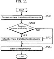
- FIG. 11 is a flow chart showing the procedures of a change process of a view transformation matrix and a transformation process from a global coordinate system into a view coordinate system in the case of using a display correction flag in the map display apparatus according to the second embodiment of the present invention.
- map display apparatus As examples of the map display apparatus according to the present invention, there are a car navigation apparatus, a cellular phone, a digital TV, a Personal Computer (PC), a Personal Digital Assistant (PDA), and the like respectively comprising a three-dimensional map display function. Also, the above mentioned examples are the apparatuses comprising a screen which can display a map.
- a car navigation apparatus a cellular phone, a digital TV, a Personal Computer (PC), a Personal Digital Assistant (PDA), and the like respectively comprising a three-dimensional map display function.
- PC Personal Computer
- PDA Personal Digital Assistant
- FIG. 6 is block diagram showing a part of the configuration of the map display apparatus according to the first embodiment of the present invention.
- the map display apparatus generates a three-dimensional image from the electronic map data, and displays the map on the screen.
- the map display apparatus comprises: a map data storage unit 101 for storing map data such as location information and height information of the object displayed on the screen; a map rendering data generation unit 102 for (i) acquiring map data from the map data storage unit 101 and (ii) generating map rendering data such as form data of the object; a rendering unit 103 for (i) executing a rendering process on the map rendering data generated by the map data generation unit and (ii) generating an image to be displayed on the screen; and a display unit 104 for displaying the image generated by the rendering unit 103 on the actual screen such as a display.
- the map data storage unit 101 stores map data such as location information according to the latitude and longitude of the roads, blocks and geography which are displayed on the screen, height information, attribute information (for example, what the object is, color and the like), and three-dimensional building data for indicating the three-dimensional object to be displayed on the screen.
- each vertex coordinate Pi of the polygonal column shape of the building is a two-dimensional coordinate.
- the attributes for rendering the polygonal column shape of the building there are: color; texture which is an image attached to a plane; plane information such as index forming a plane; information indicating the type of building; and the like.
- the map rendering data generation unit 102 based on the map data stored in the map data storage unit 101 , generates (i) form data including (a) the coordinate of element vertexes forming the plane, line and dot of a three-dimensional object and (b) connection information of the element vertexes and (ii) map rendering data including rendering information such as (a) color value for rendering an object and (b) texture image.
- the map rendering data generation unit 102 includes: an object generation unit 102 a ; a local-to-global transformation unit 102 b ; a view transformation matrix generation unit 102 c ; a view transformation matrix change unit 102 d ; and a view transformation unit 102 e.
- the object generation unit 102 a executes a generation process of a three-dimensional object which is a building and the like displayed on the screen using the map data such as the latitude and longitude, the height information and the building type.
- Qi is a vertex coordinate forming the bottom plane of the flat plane with the polygonal column height of 0.
- Each vertex coordinate of the three-dimensional object calculated in the object generation unit 102 a is in the local coordinate system which is a coordinate system whose center is the three-dimensional object.
- the object generation unit 102 a calculates the arrangement of vertex numbers forming N number of side planes and one top plane.
- the color and texture of each plane which are rendering information are assigned depending on the normal direction of a plane. For example, as for the color of an object, the irradiation amount of the light on a plane can be calculated using the light source position and plane normal line, and brightness of the color to be rendered can be calculated in real time. In the case where the rendering information is included in the three-dimensional building data in advance, the object generation unit 102 a assigns the color and texture of each plane based on the three-dimensional building data.
- the local-to-global transformation unit 102 b executes a process of transforming a local coordinate system which centers the three-dimensional object into an even larger global coordinate system, using a local-to-global transformation matrix of four rows and four columns.
- the view transformation matrix generation unit 102 c generates a view transformation matrix which transforms the global coordinate system into a view coordinate system in which (i) the view coordinate is the origin point, (ii) the view direction is the depth direction (“z” axis), and (iii) the vertical rising direction is the height direction (“y” axis).
- the view transformation matrix change unit 102 d forms a correction means, and changes a view transformation matrix of four rows and four columns for transforming, into a view coordinate system, the coordinate of the global coordinate system generated in the view transformation matrix generation unit 102 c .
- the view transformation matrix change unit 102 d changes, to 0, (i) the term regarding the “y” coordinate of the first row regarding the transformation of the view transformation matrix into “x” (the term of the second column in the first row) and (ii) the term regarding the “y” coordinate of the third row regarding the transformation of the view transformation matrix into “z” (the term of the second column in the third row).
- the view transformation matrix change unit 102 c changes, to 0, (i) the term regarding the “y” coordinate of the first column regarding the transformation of the view transformation matrix into “x” (the term of the first column in the second row) and (ii) the term regarding the “y” coordinate of the third column regarding the transformation of the view transformation matrix into “z” (the term of the third column in the second row).
- the view transformation unit 102 e executes a process of transforming, into a view coordinate system, each vertex coordinate of the three-dimensional object on a global coordinate system, using the view transformation matrix inputted from the view transformation matrix change unit 102 d .
- the view transformation unit 102 e using the changed view transformation matrix, transforms, into the three-dimensional coordinate T′ (X′, Y′,Z′,1) of the view coordinate system, all of the vertex coordinates T (X,Y,Z,1) forming the form data included in the map rendering data.
- the component of the fourth row of both the vertex coordinate T (X,Y,Z,1) in time of the transformation and the vertex coordinate T′ (X′,Y′,Z′,1) after the transformation is 1.
- the view coordinate is one point in the global coordinate system, and set based on, for example, a user's direction, a current position (self-vehicle position) of a mobile vehicle which has a map display apparatus, and the like.
- the rendering unit 103 on the three-dimensional map rendering data processed in the map rendering data generation unit 102 , (i) executes a rendering process so as to projection-transform on the actual two-dimensional screen, and (ii) generates an image to be displayed on the screen.
- the rendering unit 103 includes a projection-transformation unit 103 a and a viewport-transformation unit 103 b.
- the projection-transformation unit 103 a (i) sets a projection-transformation matrix for each vertex coordinate of the three-dimensional object in the view coordinate system transformed in the view transformation unit 102 e , and (ii) executes a projection-transformation process so as to project each vertex coordinate of the three-dimensional building object onto the two-dimensional screen.
- FIG. 8 is an illustration of the projection-transformation process in the projection-transformation unit 103 a .
- a rendering area 301 and map rendering data 302 are displayed in the three-dimensional coordinate system on the global coordinate.
- the projection-transformation unit 103 a determines a projection-transformation matrix of four rows and four columns determined by a viewpoint 303 which is arranged in the position corresponding to the view coordinate, and a view vector.
- the projection-transformation unit 103 a (i) executes a matrix transformation of the three-dimensional vertex coordinate of a three-dimensional building object and the like, using the projection-transformation matrix, and (ii) transforms the three-dimensional vertex coordinate into the coordinate system of a two-dimensional screen 304 .
- a projected image 305 is displayed on the screen 304 of the map display apparatus.
- the projection-transformation generally an object close to the viewpoint 303 is rendered large, and an object far from the viewpoint is rendered small.
- the projection-transformation unit 103 a executes a filling process on each plane of a three-dimensional object, based on the vertex coordinate data on which the projection-transformation has been executed.
- the projection-transformation unit 104 a may execute a hidden-surface removal process, based on the information regarding the depth from the viewpoint, called Z value calculated by the projection transformation process.
- the hidden-surface removal process is a process to detect an object and a plane which cannot be viewed from the viewpoint 303 , and execute control not to render the above mentioned object and plane.
- a Z buffer method for providing depth information to each pixel unit of the screen, judging the depth information in time of rendering for each pixel, and rendering only the front side
- a Z sort method for permutating each plane to be rendered in the order of the depth, and sequentially rendering from the farthest plane to the viewpoint, and the like.
- the viewport-transformation unit 103 b executes matrix transformation of each vertex coordinate of a three-dimensional object, using a viewport-transformation matrix for adjusting, to a proper size of the final display area, the image which has been projection-transformed in the projection-transformation unit 103 a .
- the viewport indicates a square-shaped area which has a width and height of an area that is smaller than the screen, and the viewport-transformation unit 103 b changes the viewport-transformed coordinate into a screen coordinate (Sx, Sy) which is a coordinate on the two-dimensional screen.
- the display unit 104 acquires a screen coordinate (Sx, Sy) determined by the viewport-transformation unit 103 b , and displays rendering data on the display which is the actual screen of the map display apparatus.
- FIG. 7 is a flow chart for calculating a coordinate of the three-dimensional object displayed on the screen of the map display apparatus according to the present embodiment.
- the object generation unit 102 a reads out plane information including: a vertex coordinate (for example, (X, Y, height)) which is map data of an object stored in the map data storage unit 101 ; color data; texture data; index forming plane data; and the like (S 201 ).
- the object generation unit 102 a extracts (a) location information such as latitude and longitude of each vertex in the rectangular area of a building generated on the screen and (b) height information of each vertex which have been acquired from the map data storage unit 101 , (ii) provides the location information and height information to each vertex of the rectangular area of the building, and (iii) generates a three-dimensional building object displayed as polygonal column data (S 202 ). Also, the object generation unit 102 a sets the vertex color of the three-dimensional building object based on the map data.
- a vertex coordinate for example, (X, Y, height)
- the object generation unit 102 a sets the vertex color of the three-dimensional building object
- the local-to-global transformation unit 102 b sets a local-to-global transformation matrix, (ii) matrix-transforms the local coordinate (X,Y,Z,1) of each vertex acquired from the object generation unit 102 a , using the local-to-global transformation matrix, and (iii) sets the global coordinate (X′,Y′,Z′, 1) (S 203 and S 204 ).
- the view transformation matrix generation unit 102 c generates a view transformation matrix for transforming a global coordinate system into a view coordinate system in which (i) the view coordinate is the origin point, (ii) the view direction is the depth direction (“z” axis), and (iii) the vertical rising direction is the height direction (“y” axis).
- the view transformation matrix change unit 102 d changes, to 0, (i) the value of the second column in the first row and (ii) the value of the second column in the third row in the view transformation matrix.
- the view transformation matrix change unit 102 d changes, to 0, (i) the value of the first column in the second row and (ii) the value of the third column in the second row in the view transformation matrix.
- the view transformation unit 102 e using the changed view transformation matrix, transforms and sets the coordinate of the three-dimensional object, from the global coordinate system into the view coordinate system (S 205 and S 206 ).
- the view coordinate system not only each vertex coordinate of the three-dimensional object, but also all of the necessities such as a view coordinate and a light source are arranged in the view coordinate system.
- the projection-transformation unit 103 a determines a projection-transformation matrix for (a) transforming each vertex coordinate of a three-dimensional object in the view coordinate system, according to the distance from the view coordinate, so that the closer the vertex coordinate is, the larger it becomes, and the farther the vertex coordinate is, the smaller it becomes.
- the projection-transformation unit 103 a also executes a matrix transformation process for transforming the view coordinate into a screen coordinate (S 207 ). In such case as described above, the projection-transformation unit 103 a sets a clipping coordinate so as to remove unnecessary line and plane of the object (S 208 ).
- the viewport-transformation unit 103 b in order to adjust the three-dimensional object to the display position and size on the actual screen, (i) transforms each coordinate of the three-dimensional object by the viewport-transformation (S 209 ), and (ii) finally sets a screen coordinate which is a coordinate on the screen of the map display apparatus (S 210 ).
- FIG. 9 is a flow chart showing specific procedures of a change process of a view transformation matrix and a transformation process from a global coordinate system into a view coordinate system in the map display apparatus according to the present embodiment (S 205 ).
- the global coordinate of the three-dimensional object set by the local-to-global transformation unit 102 b is read out (S 401 ).
- the view transformation matrix generation unit 102 c generates a view transformation matrix based on the global coordinate, a view coordinate and a view direction (S 402 ).
- the view transformation matrix change unit 102 d for the view transformation matrix, changes (i) the value of the second column in the first row and (ii) the value of the second column in the third row in the view transformation matrix so that the “x” coordinate and the “z” coordinate after transformation should not change due to the “y” coordinate of the global coordinate system (S 403 ).
- the view transformation unit 102 e executes transformation process on each read-out vertex coordinate of the three-dimensional object (S 404 ). Due to the changed view transformation matrix, each vertex coordinate of the three-dimensional object is transformed so that the value of the “x” coordinate and the value of the “z” coordinate after transformation should not be affected by the “y” coordinate. Then, since the component regarding the “y” coordinate remains (the second row) as a regular view transformation matrix, a regular view transformation is executed on the “y” coordinate (S 405 ).
- the view transformation unit 102 e finishes the loop (S 406 ).
- FIG. 10 is a display example of the screen of the map display apparatus according to the present embodiment.
- the farther a building exists from the view line the more leaned the building is rendered.
- the border line of the vertical direction of the building is leaned, and jaggies appear.
- the building can be displayed beautifully without jaggies.
- the transformation process from the global coordinate system into the view coordinate system is executed.
- the data regarding the horizontal direction (“x” axis direction) and the depth (“z” axis direction) of the map screen is correctly retained, the data regarding the vertical direction (“y” axis direction) can be corrected, and the building which exists on the screen end can be displayed straight in the screen vertical direction. Therefore, jaggies do not appear, and the building can be beautifully displayed.
- the view transformation matrix change unit 102 d the view transformation matrix is always changed.
- the above mentioned change of the view transformation matrix is not mandatory.
- a configuration comprising a selecting unit for selecting whether or not to change the view transformation matrix is conceivable. Thereby, it is possible to select, according to need, a display including a regular perspective distortion or a display displaying a three-dimensional object straight in the vertical direction of the screen.
- the example of the map display apparatus which operates independently has been explained, but there are other cases as well.
- the terminal apparatus such as a Personal Digital Assistant (PDA) and a cellular phone
- the three-dimensional map image data transformed into a screen coordinate system can be transmitted to the terminal apparatus, and a three-dimensional map can be displayed on the screen of the terminal apparatus.
- PDA Personal Digital Assistant
- the second embodiment the case of determining whether or not to execute a correction for each building, based on the display correction flag included in map data, and displaying will be explained.
- the configuration of the present embodiment is the same as the configuration of the first embodiment, the present embodiment will be explained using FIG. 6 . An explanation for the same parts as the first embodiment will be omitted.
- the differences of the second embodiment from the first embodiment are: the three-dimensional building data stored in the map data storage unit 101 ; and the operation of the view transformation matrix change unit 102 d .
- the rest of the configuration is the same as the first embodiment.
- the view transformation matrix change unit 102 d judges whether or not the display correction flag indicates changing the view transformation matrix (display correction flag is ON). In the case where the display correction flag indicates ON, the view transformation matrix change unit 102 d changes the view transformation matrix. In the case where the display correction flag does not indicate ON, the view transformation matrix change unit 102 d does not change the view transformation matrix.
- FIG. 11 is a flow chart showing the procedures of the change process of the view transformation matrix and the transformation process from the global coordinate system to the view coordinate system, in the case of using the display correction flag, in the map display apparatus according to the present embodiment.
- the explanation is simplified compared to the explanation for the first embodiment using FIG. 9 .
- the view transformation matrix generation unit 102 c generates a view transformation matrix, based on the global coordinate, the view coordinate and the view direction (S 501 ).
- the view transformation matrix change unit 102 d judges whether or not the display correction flag of the three-dimensional flag indicates ON (S 502 ). As a result, in the case where the display correction flag indicates ON (YES in S 502 ), the view transformation matrix change unit 102 d changes the view transformation matrix (S 503 ).
- the view transformation matrix change unit 102 d for the view transformation matrix, changes, to 0, (i) the value of the second column in the first row and (ii) the value of the second column in the third row in the view transformation matrix so that the “x” coordinate and the “z” coordinate after transformation do not change due to the “y” coordinate of the global coordinate system.
- the view transformation unit 102 e executes a transformation process on each vertex coordinate of the three-dimensional object read out using the changed view transformation matrix (S 504 ).
- each vertex coordinate of the three-dimensional object is transformed so that the value of the “x” coordinate and the value of the “z” coordinate after transformation should not be affected by the “y” coordinate of the global coordinate system.
- the view transformation matrix change unit 102 d does not change the view transformation matrix, and the view transformation unit 102 e executes a transformation process on each vertex coordinate of the three-dimensional object read out using a regular view transformation matrix which has not been changed (S 504 ).
- a regular view transformation is executed.
- whether or not to execute a correction for each building is determined based on the display correction flag, but there are other cases as well.
- a configuration comprising a selection unit for selecting one of (i) not executing correction for all, (ii) determining whether or not to execute a correction for each building, based on the display correction flag, or (iii) executing corrections for all.
- the present embodiment has the configuration in which a display correction flag is held for each building, and whether or not a correction is executed for each building is determined based on the display correction flag, but there are other cases as well.
- a configuration which has the display correction flag for each building block including a plurality of buildings is conceivable, and whether or not a correction is executed for each building block may be determined based on the display correction flag.
- the map display apparatus can beautifully display a building which is a three-dimensional object, and is useful for, for example, displaying a three-dimensional map on the screen of a car navigation apparatus, a PDA, a cellular phone and the like.
Applications Claiming Priority (2)
| Application Number | Priority Date | Filing Date | Title |
|---|---|---|---|
| JP2003384313 | 2003-11-13 | ||
| JP2003-384313 | 2003-11-13 |
Publications (2)
| Publication Number | Publication Date |
|---|---|
| US20050104881A1 US20050104881A1 (en) | 2005-05-19 |
| US7460120B2 true US7460120B2 (en) | 2008-12-02 |
Family
ID=34431481
Family Applications (1)
| Application Number | Title | Priority Date | Filing Date |
|---|---|---|---|
| US10/984,840 Expired - Fee Related US7460120B2 (en) | 2003-11-13 | 2004-11-10 | Map display apparatus |
Country Status (3)
| Country | Link |
|---|---|
| US (1) | US7460120B2 (zh) |
| EP (1) | EP1531322A3 (zh) |
| CN (1) | CN100587722C (zh) |
Cited By (6)
| Publication number | Priority date | Publication date | Assignee | Title |
|---|---|---|---|---|
| US20070040832A1 (en) * | 2003-07-31 | 2007-02-22 | Tan Tiow S | Trapezoidal shadow maps |
| US20070159527A1 (en) * | 2006-01-09 | 2007-07-12 | Samsung Electronics Co., Ltd. | Method and apparatus for providing panoramic view with geometric correction |
| US20080043019A1 (en) * | 2006-08-16 | 2008-02-21 | Graham Sellers | Method And Apparatus For Transforming Object Vertices During Rendering Of Graphical Objects For Display |
| US20080215235A1 (en) * | 2006-10-09 | 2008-09-04 | Marek Strassenburg-Kleciak | Selection and insertion of static elements in digital maps |
| US9129429B2 (en) | 2012-10-24 | 2015-09-08 | Exelis, Inc. | Augmented reality on wireless mobile devices |
| US20200348140A1 (en) * | 2017-12-27 | 2020-11-05 | Bayerische Motoren Werke Aktiengesellschaft | Deformation Correction of a Digital Map for a Vehicle |
Families Citing this family (27)
| Publication number | Priority date | Publication date | Assignee | Title |
|---|---|---|---|---|
| KR100669900B1 (ko) * | 2004-12-16 | 2007-01-17 | 한국전자통신연구원 | 이미지 기반의 볼륨 데이터 제거 방법 |
| KR100610689B1 (ko) * | 2005-06-24 | 2006-08-09 | 엔에이치엔(주) | 3차원 화면에 동영상을 삽입하는 방법 및 이를 위한 기록매체 |
| JP2007280212A (ja) * | 2006-04-10 | 2007-10-25 | Sony Corp | 表示制御装置、表示制御方法及び表示制御プログラム |
| US8453060B2 (en) * | 2006-08-25 | 2013-05-28 | Microsoft Corporation | Panoramic ring user interface |
| EP2102604A1 (en) * | 2007-01-10 | 2009-09-23 | TomTom International B.V. | A navigation device and a method of operating the navigation device with emergency service access |
| CN101573589B (zh) * | 2007-01-10 | 2015-12-16 | 通腾科技股份有限公司 | 导航装置及用于强化的地图显示的方法 |
| CN100476349C (zh) * | 2007-10-17 | 2009-04-08 | 南京大学 | 多关联工程图环境下全局坐标系的自动计算方法 |
| CN100476350C (zh) * | 2007-10-17 | 2009-04-08 | 南京大学 | 多关联工程图环境下全局坐标的自动定位方法 |
| WO2009132679A1 (en) * | 2008-05-02 | 2009-11-05 | Tomtom International B.V. | Navigation device & method |
| BRPI0822712A2 (pt) * | 2008-05-29 | 2015-07-07 | Tomtom Internac B V | Geração de uma imagem de exibição |
| CN102308276B (zh) * | 2008-12-03 | 2014-12-17 | 轩江 | 利用某些视觉效果来显示对象 |
| EP2244242A1 (en) * | 2009-04-23 | 2010-10-27 | Wayfinder Systems AB | Method and device for improved navigation |
| US8581905B2 (en) * | 2010-04-08 | 2013-11-12 | Disney Enterprises, Inc. | Interactive three dimensional displays on handheld devices |
| JP5136671B2 (ja) * | 2010-05-13 | 2013-02-06 | 株式会社デンソー | 地図表示装置 |
| CN102385640A (zh) * | 2010-08-27 | 2012-03-21 | 卡斯柯信号有限公司 | 微机监测图纸自动生成信息处理方法 |
| US8892357B2 (en) * | 2010-09-20 | 2014-11-18 | Honeywell International Inc. | Ground navigational display, system and method displaying buildings in three-dimensions |
| US9111386B2 (en) | 2010-11-02 | 2015-08-18 | Covidien Lp | Image viewing application and method for orientationally sensitive display devices |
| CN102538802B (zh) * | 2010-12-30 | 2016-06-22 | 上海博泰悦臻电子设备制造有限公司 | 三维导航显示方法以及相关装置 |
| CN108095761B (zh) | 2012-03-07 | 2021-10-15 | 齐特奥股份有限公司 | 空间对准设备、空间对准系统及用于指导医疗过程的方法 |
| JP2014006674A (ja) * | 2012-06-22 | 2014-01-16 | Canon Inc | 画像処理装置及びその制御方法、プログラム |
| WO2014020663A1 (ja) * | 2012-07-30 | 2014-02-06 | 三菱電機株式会社 | 地図表示装置 |
| US10275933B2 (en) * | 2013-05-24 | 2019-04-30 | Thomson Licensing | Method and apparatus for rendering object for multiple 3D displays |
| US10617401B2 (en) | 2014-11-14 | 2020-04-14 | Ziteo, Inc. | Systems for localization of targets inside a body |
| CN104916132B (zh) * | 2015-05-14 | 2017-02-01 | 扬州大学 | 一种确定交叉口交通流行驶轨迹的方法 |
| CN111148967B (zh) * | 2017-09-29 | 2024-03-08 | 松下电器(美国)知识产权公司 | 三维数据制作方法、客户端装置以及服务器 |
| WO2020210532A1 (en) | 2019-04-09 | 2020-10-15 | Ziteo, Inc. | Methods and systems for high performance and versatile molecular imaging |
| CN111503524B (zh) * | 2020-04-28 | 2022-03-01 | 深圳市爱路恩济能源技术有限公司 | 一种匹配城市燃气用户和调压箱的方法 |
Citations (36)
| Publication number | Priority date | Publication date | Assignee | Title |
|---|---|---|---|---|
| US3576427A (en) * | 1967-01-19 | 1971-04-27 | Bernard M Taylor Jr | Perspective or orthographic plotter |
| US5101475A (en) * | 1989-04-17 | 1992-03-31 | The Research Foundation Of State University Of New York | Method and apparatus for generating arbitrary projections of three-dimensional voxel-based data |
| US5495576A (en) * | 1993-01-11 | 1996-02-27 | Ritchey; Kurtis J. | Panoramic image based virtual reality/telepresence audio-visual system and method |
| US5509112A (en) * | 1990-09-21 | 1996-04-16 | Kabushiki Kaisha Toshiba | Presentation support environment system |
| US5616031A (en) * | 1991-03-21 | 1997-04-01 | Atari Games Corporation | System and method of shadowing an object in motion |
| JPH09281889A (ja) | 1996-04-16 | 1997-10-31 | Hitachi Ltd | 地図表示装置及び地図表示方法 |
| US5847711A (en) * | 1994-09-06 | 1998-12-08 | The Research Foundation Of State University Of New York | Apparatus and method for parallel and perspective real-time volume visualization |
| US5913918A (en) * | 1995-06-13 | 1999-06-22 | Matsushita Electric Industrial Co., Ltd. | Automotive navigation apparatus and recording medium storing program therefor |
| US5986662A (en) * | 1996-10-16 | 1999-11-16 | Vital Images, Inc. | Advanced diagnostic viewer employing automated protocol selection for volume-rendered imaging |
| US6072497A (en) * | 1997-05-30 | 2000-06-06 | Hewlett-Packard Company | Volumetric pre-clipping method that guarantees minimal number of sample points through a volume |
| EP1037188A2 (en) | 1999-03-16 | 2000-09-20 | Hitachi, Ltd. | Three-dimensional map drawing method and navigation apparatus |
| DE10023160A1 (de) | 1999-05-12 | 2000-11-30 | Denso Corp | Kartenanzeigevorrichtung |
| US6222551B1 (en) * | 1999-01-13 | 2001-04-24 | International Business Machines Corporation | Methods and apparatus for providing 3D viewpoint selection in a server/client arrangement |
| US6278460B1 (en) * | 1998-12-15 | 2001-08-21 | Point Cloud, Inc. | Creating a three-dimensional model from two-dimensional images |
| US6285317B1 (en) * | 1998-05-01 | 2001-09-04 | Lucent Technologies Inc. | Navigation system with three-dimensional display |
| US20010020211A1 (en) * | 2000-02-14 | 2001-09-06 | Kuniharu Takayama | Navigation information presenting apparatus and method thereof |
| US6292745B1 (en) * | 2000-07-24 | 2001-09-18 | Navigation Technologies Corp. | Method and system for forming a database of geographic data for distribution to navigation system units |
| US20010026276A1 (en) * | 2000-03-17 | 2001-10-04 | Kiyomi Sakamoto | Map display device and navigation device |
| US20010037177A1 (en) * | 2000-04-28 | 2001-11-01 | Sosuke Nishida | Navigation system |
| EP1189030A2 (en) | 2000-09-13 | 2002-03-20 | Hitachi, Ltd. | Terminal apparatus for downloading map |
| US20020041717A1 (en) * | 2000-08-30 | 2002-04-11 | Ricoh Company, Ltd. | Image processing method and apparatus and computer-readable storage medium using improved distortion correction |
| US20020062360A1 (en) * | 2000-11-17 | 2002-05-23 | Nec Corporation | Information delivering server and clients and method thereof and storing medium stored programs to execute information delivery |
| US20020085014A1 (en) * | 2000-12-28 | 2002-07-04 | Masato Yuda | Rendering device |
| US6452544B1 (en) * | 2001-05-24 | 2002-09-17 | Nokia Corporation | Portable map display system for presenting a 3D map image and method thereof |
| US20030023412A1 (en) * | 2001-02-14 | 2003-01-30 | Rappaport Theodore S. | Method and system for modeling and managing terrain, buildings, and infrastructure |
| US6573893B1 (en) * | 2000-11-01 | 2003-06-03 | Hewlett-Packard Development Company, L.P. | Voxel transfer circuit for accelerated volume rendering of a graphics image |
| US20030154021A1 (en) * | 2000-08-24 | 2003-08-14 | Thomas Delling | Method for obtaining a map representation, and a navigation device |
| US6628279B1 (en) * | 2000-11-22 | 2003-09-30 | @Last Software, Inc. | System and method for three-dimensional modeling |
| US20030214502A1 (en) * | 2001-11-27 | 2003-11-20 | Samsung Electronics Co., Ltd. | Apparatus and method for depth image-based representation of 3-dimensional object |
| US20040125103A1 (en) * | 2000-02-25 | 2004-07-01 | Kaufman Arie E. | Apparatus and method for volume processing and rendering |
| US20040176908A1 (en) * | 2003-03-07 | 2004-09-09 | Keiichi Senda | Map displaying apparatus |
| US6798409B2 (en) * | 2000-02-07 | 2004-09-28 | British Broadcasting Corporation | Processing of images for 3D display |
| US20050004749A1 (en) * | 2003-06-03 | 2005-01-06 | Young-Sik Park | Apparatus and method for downloading and displaying images relating to global positioning information in a navigation system |
| US20050159886A1 (en) * | 2004-01-20 | 2005-07-21 | Lg Electronics Inc. | Method for converting coordinate values of map data |
| US20050179688A1 (en) * | 2004-02-17 | 2005-08-18 | Chernichenko Dmitry A. | Method and apparatus for correction of perspective distortion |
| US20060078224A1 (en) * | 2002-08-09 | 2006-04-13 | Masashi Hirosawa | Image combination device, image combination method, image combination program, and recording medium containing the image combination program |
-
2004
- 2004-11-03 EP EP04026068A patent/EP1531322A3/en not_active Withdrawn
- 2004-11-10 US US10/984,840 patent/US7460120B2/en not_active Expired - Fee Related
- 2004-11-15 CN CN200410095738A patent/CN100587722C/zh not_active Expired - Fee Related
Patent Citations (39)
| Publication number | Priority date | Publication date | Assignee | Title |
|---|---|---|---|---|
| US3576427A (en) * | 1967-01-19 | 1971-04-27 | Bernard M Taylor Jr | Perspective or orthographic plotter |
| US5101475A (en) * | 1989-04-17 | 1992-03-31 | The Research Foundation Of State University Of New York | Method and apparatus for generating arbitrary projections of three-dimensional voxel-based data |
| US5509112A (en) * | 1990-09-21 | 1996-04-16 | Kabushiki Kaisha Toshiba | Presentation support environment system |
| US5616031A (en) * | 1991-03-21 | 1997-04-01 | Atari Games Corporation | System and method of shadowing an object in motion |
| US5495576A (en) * | 1993-01-11 | 1996-02-27 | Ritchey; Kurtis J. | Panoramic image based virtual reality/telepresence audio-visual system and method |
| US5847711A (en) * | 1994-09-06 | 1998-12-08 | The Research Foundation Of State University Of New York | Apparatus and method for parallel and perspective real-time volume visualization |
| US5913918A (en) * | 1995-06-13 | 1999-06-22 | Matsushita Electric Industrial Co., Ltd. | Automotive navigation apparatus and recording medium storing program therefor |
| JPH09281889A (ja) | 1996-04-16 | 1997-10-31 | Hitachi Ltd | 地図表示装置及び地図表示方法 |
| US5986662A (en) * | 1996-10-16 | 1999-11-16 | Vital Images, Inc. | Advanced diagnostic viewer employing automated protocol selection for volume-rendered imaging |
| US6072497A (en) * | 1997-05-30 | 2000-06-06 | Hewlett-Packard Company | Volumetric pre-clipping method that guarantees minimal number of sample points through a volume |
| US6285317B1 (en) * | 1998-05-01 | 2001-09-04 | Lucent Technologies Inc. | Navigation system with three-dimensional display |
| US6278460B1 (en) * | 1998-12-15 | 2001-08-21 | Point Cloud, Inc. | Creating a three-dimensional model from two-dimensional images |
| US6222551B1 (en) * | 1999-01-13 | 2001-04-24 | International Business Machines Corporation | Methods and apparatus for providing 3D viewpoint selection in a server/client arrangement |
| EP1037188A2 (en) | 1999-03-16 | 2000-09-20 | Hitachi, Ltd. | Three-dimensional map drawing method and navigation apparatus |
| DE10023160A1 (de) | 1999-05-12 | 2000-11-30 | Denso Corp | Kartenanzeigevorrichtung |
| US6710774B1 (en) | 1999-05-12 | 2004-03-23 | Denso Corporation | Map display device |
| US6798409B2 (en) * | 2000-02-07 | 2004-09-28 | British Broadcasting Corporation | Processing of images for 3D display |
| US20010020211A1 (en) * | 2000-02-14 | 2001-09-06 | Kuniharu Takayama | Navigation information presenting apparatus and method thereof |
| US20070206008A1 (en) * | 2000-02-25 | 2007-09-06 | The Research Foundation Of The State University Of New York | Apparatus and Method for Real-Time Volume Processing and Universal Three-Dimensional Rendering |
| US20040125103A1 (en) * | 2000-02-25 | 2004-07-01 | Kaufman Arie E. | Apparatus and method for volume processing and rendering |
| US20010026276A1 (en) * | 2000-03-17 | 2001-10-04 | Kiyomi Sakamoto | Map display device and navigation device |
| US20010037177A1 (en) * | 2000-04-28 | 2001-11-01 | Sosuke Nishida | Navigation system |
| US6591190B2 (en) * | 2000-04-28 | 2003-07-08 | Pioneer Corporation | Navigation system |
| US6292745B1 (en) * | 2000-07-24 | 2001-09-18 | Navigation Technologies Corp. | Method and system for forming a database of geographic data for distribution to navigation system units |
| US20030154021A1 (en) * | 2000-08-24 | 2003-08-14 | Thomas Delling | Method for obtaining a map representation, and a navigation device |
| US20020041717A1 (en) * | 2000-08-30 | 2002-04-11 | Ricoh Company, Ltd. | Image processing method and apparatus and computer-readable storage medium using improved distortion correction |
| EP1189030A2 (en) | 2000-09-13 | 2002-03-20 | Hitachi, Ltd. | Terminal apparatus for downloading map |
| US6573893B1 (en) * | 2000-11-01 | 2003-06-03 | Hewlett-Packard Development Company, L.P. | Voxel transfer circuit for accelerated volume rendering of a graphics image |
| US20020062360A1 (en) * | 2000-11-17 | 2002-05-23 | Nec Corporation | Information delivering server and clients and method thereof and storing medium stored programs to execute information delivery |
| US6628279B1 (en) * | 2000-11-22 | 2003-09-30 | @Last Software, Inc. | System and method for three-dimensional modeling |
| US20020085014A1 (en) * | 2000-12-28 | 2002-07-04 | Masato Yuda | Rendering device |
| US20030023412A1 (en) * | 2001-02-14 | 2003-01-30 | Rappaport Theodore S. | Method and system for modeling and managing terrain, buildings, and infrastructure |
| US6452544B1 (en) * | 2001-05-24 | 2002-09-17 | Nokia Corporation | Portable map display system for presenting a 3D map image and method thereof |
| US20030214502A1 (en) * | 2001-11-27 | 2003-11-20 | Samsung Electronics Co., Ltd. | Apparatus and method for depth image-based representation of 3-dimensional object |
| US20060078224A1 (en) * | 2002-08-09 | 2006-04-13 | Masashi Hirosawa | Image combination device, image combination method, image combination program, and recording medium containing the image combination program |
| US20040176908A1 (en) * | 2003-03-07 | 2004-09-09 | Keiichi Senda | Map displaying apparatus |
| US20050004749A1 (en) * | 2003-06-03 | 2005-01-06 | Young-Sik Park | Apparatus and method for downloading and displaying images relating to global positioning information in a navigation system |
| US20050159886A1 (en) * | 2004-01-20 | 2005-07-21 | Lg Electronics Inc. | Method for converting coordinate values of map data |
| US20050179688A1 (en) * | 2004-02-17 | 2005-08-18 | Chernichenko Dmitry A. | Method and apparatus for correction of perspective distortion |
Non-Patent Citations (3)
| Title |
|---|
| Carlbom, Ingrid; Paciorek, Joseph; "Planar Geometric Projections and Viewing Transformation;" Dec. 1978; ACM Computing Surveys, vol. 10, No. 4; pp. 465-502. * |
| Foley, van Dam, Feiner, Hughes; "Computer Graphics: Principles and Practice," 1996, Addison-Wesley Publishing Company, Inc., Second Edition, pp. 210-226 and 229-256. * |
| Suomela, Riku; Roimela, Kimmo; Lehikoinen, Juha; "The evolution of perspective view in WalkMap," Oct. 2003, Personal and Ubiquitous Computing, vol. 7, Issue 5, pp. 249-262. * |
Cited By (9)
| Publication number | Priority date | Publication date | Assignee | Title |
|---|---|---|---|---|
| US20070040832A1 (en) * | 2003-07-31 | 2007-02-22 | Tan Tiow S | Trapezoidal shadow maps |
| US20070159527A1 (en) * | 2006-01-09 | 2007-07-12 | Samsung Electronics Co., Ltd. | Method and apparatus for providing panoramic view with geometric correction |
| US7899270B2 (en) * | 2006-01-09 | 2011-03-01 | Samsung Electronics Co., Ltd. | Method and apparatus for providing panoramic view with geometric correction |
| US20080043019A1 (en) * | 2006-08-16 | 2008-02-21 | Graham Sellers | Method And Apparatus For Transforming Object Vertices During Rendering Of Graphical Objects For Display |
| US20080215235A1 (en) * | 2006-10-09 | 2008-09-04 | Marek Strassenburg-Kleciak | Selection and insertion of static elements in digital maps |
| US8918274B2 (en) * | 2006-10-09 | 2014-12-23 | Harman Becker Automotive Systems Gmbh | Selection and insertion of static elements in digital maps |
| US9129429B2 (en) | 2012-10-24 | 2015-09-08 | Exelis, Inc. | Augmented reality on wireless mobile devices |
| US10055890B2 (en) | 2012-10-24 | 2018-08-21 | Harris Corporation | Augmented reality for wireless mobile devices |
| US20200348140A1 (en) * | 2017-12-27 | 2020-11-05 | Bayerische Motoren Werke Aktiengesellschaft | Deformation Correction of a Digital Map for a Vehicle |
Also Published As
| Publication number | Publication date |
|---|---|
| US20050104881A1 (en) | 2005-05-19 |
| CN1617173A (zh) | 2005-05-18 |
| CN100587722C (zh) | 2010-02-03 |
| EP1531322A2 (en) | 2005-05-18 |
| EP1531322A3 (en) | 2007-09-05 |
Similar Documents
| Publication | Publication Date | Title |
|---|---|---|
| US7460120B2 (en) | Map display apparatus | |
| US6654020B2 (en) | Method of rendering motion blur image and apparatus therefor | |
| US5668940A (en) | Method and apparatus for anti-aliasing polygon edges in a computer imaging system | |
| US6677939B2 (en) | Stereoscopic image processing apparatus and method, stereoscopic vision parameter setting apparatus and method and computer program storage medium information processing method and apparatus | |
| US8253724B2 (en) | Terrain modeling based on curved surface area | |
| US7348996B2 (en) | Method of and system for pixel sampling | |
| US20040176908A1 (en) | Map displaying apparatus | |
| US7764292B2 (en) | Three dimensional graphics processing apparatus, image display apparatus, three dimensional graphics processing method, control program and computer-readable recording medium | |
| US9030478B2 (en) | Three-dimensional graphics clipping method, three-dimensional graphics displaying method, and graphics processing apparatus using the same | |
| JPH0375682A (ja) | 写真写実影像を高速で生成する方法 | |
| KR100723422B1 (ko) | 포인트 기반 렌더링 장치와 방법 및 컴퓨터 프로그램을 저장한 컴퓨터로 읽을 수 있는 기록매체 | |
| US6819333B1 (en) | System and method for displaying an image using display distortion correction | |
| US8098264B2 (en) | Method and apparatus for rendering computer graphics primitive | |
| US6346939B1 (en) | View dependent layer ordering method and system | |
| JP4642431B2 (ja) | 地図表示装置、地図表示システム、地図表示方法およびプログラム | |
| US20080088640A1 (en) | Outline font brightness value correction system, method and program | |
| KR101208767B1 (ko) | 곡면 투사를 이용한 입체 영상 생성 방법, 장치 및 시스템, 이를 위한 기록 매체 | |
| US20130120461A1 (en) | Image processor and image processing method | |
| US20180247392A1 (en) | Information Processing System, Information Processing Apparatus, Output Apparatus, Program, and Recording Medium | |
| KR100429092B1 (ko) | 그래픽영상처리방법및장치 | |
| US7525551B1 (en) | Anisotropic texture prefiltering | |
| US10460427B2 (en) | Converting imagery and charts to polar projection | |
| JP2001022948A (ja) | 画像処理装置および画像処理方法、並びに記録媒体 | |
| WO2019049457A1 (ja) | 画像生成装置および画像生成方法 | |
| KR100633029B1 (ko) | 풋프린트의 분석 및 수정 방법 |
Legal Events
| Date | Code | Title | Description |
|---|---|---|---|
| AS | Assignment |
Owner name: MATSUSHITA ELECTRIC INDUSTRIAL CO., LTD., JAPAN Free format text: ASSIGNMENT OF ASSIGNORS INTEREST;ASSIGNORS:YOSHIDA, TADASHI;ARAKI, HITOSHI;SENDA, KEIICHI;AND OTHERS;REEL/FRAME:015987/0005 Effective date: 20041026 |
|
| AS | Assignment |
Owner name: PANASONIC CORPORATION, JAPAN Free format text: CHANGE OF NAME;ASSIGNOR:MATSUSHITA ELECTRIC INDUSTRIAL CO., LTD.;REEL/FRAME:021897/0588 Effective date: 20081001 Owner name: PANASONIC CORPORATION,JAPAN Free format text: CHANGE OF NAME;ASSIGNOR:MATSUSHITA ELECTRIC INDUSTRIAL CO., LTD.;REEL/FRAME:021897/0588 Effective date: 20081001 |
|
| FEPP | Fee payment procedure |
Free format text: PAYOR NUMBER ASSIGNED (ORIGINAL EVENT CODE: ASPN); ENTITY STATUS OF PATENT OWNER: LARGE ENTITY |
|
| FPAY | Fee payment |
Year of fee payment: 4 |
|
| AS | Assignment |
Owner name: GODO KAISHA IP BRIDGE 1, JAPAN Free format text: ASSIGNMENT OF ASSIGNORS INTEREST;ASSIGNOR:PANASONIC CORPORATION (FORMERLY MATSUSHITA ELECTRIC INDUSTRIAL CO., LTD.);REEL/FRAME:032209/0630 Effective date: 20131203 |
|
| REMI | Maintenance fee reminder mailed | ||
| LAPS | Lapse for failure to pay maintenance fees | ||
| STCH | Information on status: patent discontinuation |
Free format text: PATENT EXPIRED DUE TO NONPAYMENT OF MAINTENANCE FEES UNDER 37 CFR 1.362 |
|
| FP | Lapsed due to failure to pay maintenance fee |
Effective date: 20161202 |