US7450124B2 - Generating 2D transitions using a 3D model - Google Patents
Generating 2D transitions using a 3D model Download PDFInfo
- Publication number
- US7450124B2 US7450124B2 US11/083,378 US8337805A US7450124B2 US 7450124 B2 US7450124 B2 US 7450124B2 US 8337805 A US8337805 A US 8337805A US 7450124 B2 US7450124 B2 US 7450124B2
- Authority
- US
- United States
- Prior art keywords
- media object
- transition
- mapped
- dimensional
- mesh
- Prior art date
- Legal status (The legal status is an assumption and is not a legal conclusion. Google has not performed a legal analysis and makes no representation as to the accuracy of the status listed.)
- Expired - Fee Related, expires
Links
Images




Classifications
-
- G—PHYSICS
- G06—COMPUTING OR CALCULATING; COUNTING
- G06T—IMAGE DATA PROCESSING OR GENERATION, IN GENERAL
- G06T1/00—General purpose image data processing
-
- G—PHYSICS
- G06—COMPUTING OR CALCULATING; COUNTING
- G06T—IMAGE DATA PROCESSING OR GENERATION, IN GENERAL
- G06T13/00—Animation
-
- G—PHYSICS
- G06—COMPUTING OR CALCULATING; COUNTING
- G06T—IMAGE DATA PROCESSING OR GENERATION, IN GENERAL
- G06T7/00—Image analysis
-
- G—PHYSICS
- G11—INFORMATION STORAGE
- G11B—INFORMATION STORAGE BASED ON RELATIVE MOVEMENT BETWEEN RECORD CARRIER AND TRANSDUCER
- G11B27/00—Editing; Indexing; Addressing; Timing or synchronising; Monitoring; Measuring tape travel
- G11B27/02—Editing, e.g. varying the order of information signals recorded on, or reproduced from, record carriers
- G11B27/031—Electronic editing of digitised analogue information signals, e.g. audio or video signals
- G11B27/034—Electronic editing of digitised analogue information signals, e.g. audio or video signals on discs
-
- G—PHYSICS
- G06—COMPUTING OR CALCULATING; COUNTING
- G06T—IMAGE DATA PROCESSING OR GENERATION, IN GENERAL
- G06T2210/00—Indexing scheme for image generation or computer graphics
- G06T2210/44—Morphing
Definitions
- Embodiments of the present invention generally relate to the field of graphics animation and processing.
- embodiments of this invention relate to generating two dimensional transitions using a three dimensional model and the processing capabilities of a graphics processing unit.
- a hardware interface e.g., a graphical device interface (GDI)
- GDI graphical device interface
- the GDI is responsible for drawing items (such as dialog boxes, buttons, and other graphical elements) in a consistent style on a screen by calling the appropriate display drivers and passing them the information on the items to be drawn.
- a software program typically uses a set of routines, such as those provided in a software development kit (SDK) library to configure these software applications to call GDI functions.
- SDK software development kit
- a SDK library includes functions such as icon operations, rectangle operations, or the like.
- GDI features are executed by a central processing unit (CPU).
- CPU central processing unit
- graphics elements and images such as rendering 2D images, video streams, or the like.
- the additional graphical processing impedes overall performances of the CPU and a computer system because graphical processing requires extensive calculations of graphical parameters, such as pixel or texture calculation, rendering or animation of images, or the like. While CPU processing of these graphics or images is adequate, an improvement in graphics or image processing is desirable.
- a system and method for delegating or shifting graphics processing tasks to a graphics processing unit is desirable by using a 3D model and fixed pipeline functions of the GPU to create two dimensional graphical effects.
- a system and method for creating two dimensional graphics effects using a set of instructions for processing the two dimensional effects in the 3D coordinate system is desired.
- Embodiments of the present invention overcome one or more disadvantages of the prior art by implementing two dimensional transitions using a three dimensional coordinate system. Instead of sending the transformed data relating to two dimensional transitions to the CPU to perform matrix calculations, pixel or texture calculations, embodiments of the present invention send data to the GPU, without sending them to the CPU, so that the GPU may process the data more efficiently.
- the GPU may render media objects, animations or other graphical elements onto a video buffer to be ready for display.
- a set of computer-executable instructions or software applications may process the data in the 3D coordinate system to create two dimensional effects.
- embodiments of the present invention reduce bus traffic, CPU load, and assist in shorten rendering time of processing of transitions, animations, or other graphical transformations.
- embodiments of the present invention make some transitions between media objects or images (e.g., dissolve, cross-fade or simple wipe transitions) take up less CPU time and make developing new visual variants and transition patterns more efficiently.
- This design provides users a rich collection of visual variants by mixing wipe patterns, rendering techniques, and parameters.
- Embodiments of the present invention also use the GPU fixed function pipeline to execute and process three dimensional media objects while producing two dimensional graphical effects on a large proportion of machines currently in the market.
- embodiments of the invention may use fixed function pipeline of a set of instructions or software applications to process three dimensional media objects to produce two dimensional graphical effects.
- a method generates a two dimensional transition between a first media object and a second media object using a graphics processing unit.
- a three dimensional model corresponding to a desired two dimensional transition pattern is defined.
- a transition between the first media object and the second media object is generated as a function of the defined three dimensional model using the graphics processing unit.
- a system generates a two dimensional transition between a first media object and a second media object.
- An interface receives the first media object, the second media object, and a transition pattern mesh.
- a transition generator maps a plurality of vertices of the received first media object to a first mesh to create a first mapped media object.
- the transition generator maps a plurality of vertices of the received second media object to the transition pattern mesh to create a second mapped media object.
- a graphics processor renders the transition between the first media object and the second media object from the first mapped media object and the second mapped media object.
- a system generates a transition between a first media object and a second media object.
- a first processor or first set of instructions renders the first media object and the second media object.
- An interface receives the first media object, the second media object, and a transition pattern mesh.
- a transition generator maps a plurality of vertices of the received first media object to a first mesh to create a first mapped media object.
- the transition generator maps a plurality of vertices of the received second media object to the received transition pattern mesh to create a second mapped media object.
- a second processor or second set of instructions independent of the first processor or the first set of instructions, for rendering the transition between the first media object and the second media object from the first mapped media object and the second mapped media object.
- the invention may comprise various other methods and apparatuses.
- FIG. 1 is a block diagram illustrating a system for generating a two dimensional transition between a first media object and a second media object according to one embodiment of the invention.
- FIG. 2A is a diagram illustrating a three dimensional model according to one embodiment of the invention.
- FIG. 2B is a diagram illustrate an orthogonal projection transform according to one embodiment of the invention.
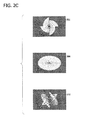
- FIG. 2C is an illustration of views of a transition pattern in different dimensions according to one embodiment of the invention.
- FIGS. 3A-F are diagrams illustrating an implementation of a transition pattern mesh according to one embodiment of the invention.
- FIGS. 4A-C are illustrations of an implementation of a circle wipe transition pattern using the three dimensional model according to one embodiment of the invention.
- FIGS. 5A-B are illustrations of implementations of exemplary transition patterns according to one embodiment of the invention.
- FIG. 6 is a flow chart illustrating a method for generating a two dimensional transition between a first media object and a second media object with a sharp edge of transition patterns according to one embodiment of the invention.
- FIG. 7 is a flow chart illustrating a method for creating additional effects to the transition between the first media object and the second media object according to one embodiment of the invention.
- FIG. 8 is a block diagram illustrating one example of a suitable computing system environment in which the invention may be implemented.
- FIGS. 9A-D are diagrams illustrating an example of an alpha map according to one embodiment of the invention.
- a block diagram illustrates a system 100 for generating two dimensional (2D) transitions between a first media object 102 and a second media object 104 according to one embodiment of the invention.
- a transition is a progressive change on a display from a first media object to a second media object according to a pattern.
- the first media object 102 is a white color image
- the second media object 104 is a black color image
- a user wishes to transition from the white color image to the black color image.
- transitions may be a left-to-right wipe transition in which the black color image progressively replaces the white color image from the left to the right until the black color image is fully visible and completely replaces the white color image.
- Such left-to-right wipe transition may include patterns such as a vertical line moving from left to right horizontally across the white color image and introducing the black color image to the left of the vertical line as the vertical line progressively moves from left to right until the black color image completely replaces the white color image.
- Other patterns such as a horizontal line moving vertically, two vertical lines moving from the center, or the like patterns may be implemented.
- the system 100 may be a system 130 as illustrated in FIG. 8 or other computerized system that includes a first processor 114 , a second processor 118 , a display 120 , and a storage (not shown).
- system 100 includes an application program interface (API) for manipulating and displaying three dimensional (3D) objects.
- API application program interface
- the first processor 114 may be a CPU, other centralized or main processor, a first set of computer-executable instructions, or software application for processing.
- the second processor 118 may be a GPU, other secondary processor, a second set of computer-executable instructions, or software application for processing data relating a 3D model.
- first media object 102 and a second media object 104 are displayed on the display 120 .
- the first media object 102 or the second media object 104 may be a file or a collection of files for a still image, a video stream, or other graphical elements (e.g., icons, buttons, web pages, or the like) to be displayed on display 120 .
- a user may wish to create a smooth or other interesting transition between first media object 102 and second media object 104 in a timeline.
- the user may want viewers to focus on the story portrayed through the media objects and not the transitions and/or effects. As such, the user may want create the transition with subtle effects and variations.
- the user may want the trophy to make a grand entrance to the scene by creating a transition between first media object 102 and second media object 104 so that the trophy presentation is pronounced.
- the user may generate a subtle transition (such as soft edge, dissolve edge, and/or fancy edge transition) to transition viewers to the end of a movie scene.
- the first media object 102 and second media object 104 are received by an interface 108 .
- the interface 108 may be a graphical user interface (GUI) of a software application or other interface means to receive first media object 102 and second media object 104 .
- GUI graphical user interface
- the first media object 102 and second media object 104 may be input to interface 108 from a non-volatile storage, a volatile storage, or the like, via a direct transmission such as a communication network (e.g., a system bus, internet, intranet, or the like).
- a communication network e.g., a system bus, internet, intranet, or the like.
- the user may create a wipe transition between first media object 102 and second media object 104 .
- a wipe transition is a 2D graphical effect (e.g., second media object 104 moving across the computer display from left to right to replace first media object 102 )
- embodiments of the present invention defines a 3D model (e.g., x-,y-, z-coordinate system) for any given transition.
- FIG. 2A is a block diagram illustrating a 3D model 200 according to one embodiment of the invention.
- the model 200 shows a 3D view space 204 with three axes: x-axis, y-axis and z-axis.
- the 3D view space 204 is configured to adapt to different screen aspect ratio (e.g., 4 ⁇ 3 or 16 ⁇ 9) of display 120 .
- the model 200 also illustrates an eye 202 to show that the viewer is looking at the direction opposite to the z-axis (as shown by arrow 212 ). In other words, the z-axis points to the viewer.
- FIG. 2B a diagram illustrates an orthogonal projection transform 214 for mapping a 2D media object to a 3D model according to one embodiment of the invention.
- the transform 214 is a 2D square having an x-axis along the horizontal edge and a y-axis being perpendicular to the x-axis.
- the length and width of transform 214 is set to 1 unit such that the visible range is 0 to 1. That is, the transform 214 is a 1 ⁇ 1 unit square. It is to be understood that other shapes or polygons (e.g., triangle, rectangles, or the like) may be used for mapping a 2D shape to a 3D model.
- a z-axis points to an eye 216 which locates above the x-y plane.
- the eye is located at the position (0.5, 0.5, 1.0) (e.g., viewing from the top of the x-y plane).
- a 2D media object may be mapped to the transform 214 (i.e., a 0,0->1.0,1.0 space) so that the 2D media object may be represented by data relating to the 3D coordinate system in the 3D model.
- Such data may be processed by the GPU, a set of computer-executable instructions, or software applications to create the 2D graphical effects.
- FIG. 2C is an illustration of views of a transition pattern in different dimensions according to one embodiment of the invention.
- views 206 , 208 and 210 depict a wheel transition in different view spaces.
- a perspective side view 206 is a wheel transition in a 3D model, as indicated by the x-y-z coordinate symbols.
- perspective view 206 simulates human vision by making objects closer to human eyes larger than objects farther from human eyes.
- an orthogonal view 208 flattens the wheel transition in 2D, as indicated by x-y coordinate symbols, to an ellipse in an aerial view.
- a transition pattern mesh view 210 from the z-axis is view of the wheel transition after the transition pattern mesh 110 is applied.
- FIGS. 3A-F are diagrams illustrating an implementation of a transition pattern mesh 110 , such as a wipe transition that replaces a first media object 304 with a second media object 306 from the center of the first media object 304 , according to one embodiment of the invention.
- first media object 304 is an image filled with lines and second media object 306 is a white colored image.
- the user viewing from the direction represented by an eye 302 , wishes to introduce second media object 306 to first media object 304 from the center. Initially, the user only sees first media object 304 as shown by 308 in FIG. 3D .
- FIG. 3D In FIG.
- the wipe transition pattern mesh is mapped onto first media object 304 to form a first mapped media object 304 ′.
- first media object 304 For example, each vertex or pixel point of first media object 304 is transformed or registered onto the transition pattern mesh, which is in 3D, so that each pixel point on the transition pattern mesh in 3D matches the corresponding vertex or pixel point on first media object 304 in 2D.
- the second media object 306 is mapped to a first mesh 106 to form a second mapped media object 306 ′, where the first mesh 106 will be discussed below.
- a first mapped media object 304 ′ moves toward a second media object 306 ′, such that the user sees what's shown by 308 ′ in FIG. 3E .
- the user begins to see the transitioning of first media object 304 to second media object 306 .
- FIG. 3C when the transition progress has completed, the user will only see a resulting second media object 306 ′′ while first mapped media object 304 ′′ is invisible to the user, as shown by 308 ′′ in FIG. 3F .
- second media object 306 ′ moves toward first mapped media object 304 ′.
- first mapped media object 304 ′ and second media object 306 ′ moves toward each other during the transition progress.
- interface 108 also receives a first mesh 106 and a transition pattern mesh 110 to which the media objects are mapped so that a transition between the media objects can be rendered.
- the first mesh 106 may be a full screen rectangle mesh for mapping vertices of first media object 102 to form a first mapped media object.
- each vertex of first media object 102 is mapped onto first mesh 106 in 3D coordinates such that the GPU or software applications may process or calculate pixel values corresponding to each vertex for display.
- transform 214 has a width of 1 unit and a length of 1 unit, creating a 1 ⁇ 1 square.
- Each of the four corners of transform 214 in 2D coordinate system, may be represented as (0,0), (1,0), (1,1) and (0,1) as shown in FIG. 2B .
- each pixel point or vertex of first media object 102 is registered or transformed to transform 214 .
- the z-coordinate of transform may be set to 0 to represent a flat 3D object.
- first mesh 106 includes vertex data of first media object 102 relating to texture coordinates (e.g., texture values relating to individual color values in a texture space in 3D).
- the Gouraud shading mode is used and the texture values are applied to fill first mesh 106 .
- Section 2 of Appendix A describes exemplary implementation of creating first mesh 106 .
- the first mesh 106 defines a set of vertices and a set of polygon faces.
- a transition generator 112 maps first media object 102 onto first mesh 106 to form the first mapped media object.
- the transition pattern mesh 110 includes transition patterns to be selected by users for transitioning from first media object 102 to second media object 104 or vice versa.
- interface 108 displays examples of a variety of transitions, such as a wipe transition with various shapes, or the like on display 120 and the user may use an input device (e.g., a mouse or a keyboard) to select a desired transition pattern.
- FIGS. 4A-C are illustrations of an implementation of circle out and circle in wipe transitions patterns using the 3D model according to one embodiment of the invention.
- FIG. 4A shows a perspective side view of a circle-out wipe transition as a transition pattern.
- An incoming or first media object 402 (after being mapped by a circle transition pattern) is shown to transition to an outgoing or second media object 418 .
- the beginning (or when z-coordinate value is near 0), the incoming or first media object 402 would appear as a small circle on the outgoing or second media object 418 .
- the user sees a circle emerge from the center of the screen or display 120 . As transition progresses, the circle becomes larger.
- the incoming or first media object 402 appears within the circle and outgoing or second media object 418 is displaced by incoming or first media object 402 as the circle becomes larger.
- the z-coordinate for the incoming or first media object 402 represents transition progress.
- the point or the small circle increases its radius from small to larger such that outgoing or second media object 418 is transitioned to incoming or first media object 402 .
- the viewing space is limited the viewer's display (e.g., display 120 ), as such, parts of the circle transition may be cropped as they may not be displayed by display 120 .
- FIG. 4 Another perspective side view a circle-in wipe transition of an incoming or second media object 404 and an outgoing or first media object 422 .
- the circle-in wipe transition starts with a larger circle to a point as incoming or second media object 404 transitions to outgoing or first media object 422 .
- FIG. 4B shows three views of a circle wipe transition.
- a screen shot 406 shows a snapshot of a first media object A transitioning to a second media object B with a circle-out wipe.
- An orthogonal view 408 shows the circle in a 2D view while a perspective side view 410 shows that the circle in a cone shape.
- embodiments of the present invention apply a circle shaped transition to the 3D model, such as model 200 , so that a 2D circle is transformed as a cone shape.
- transition pattern mesh 110 By using transition pattern mesh 110 in a 3D model, embodiments of the present invention send data relating to the 3D model for 2D transitions to second processor or a second set of instructions 118 (collectively as “second processor 118 ”) so that the 2D transitions may be processed more efficiently.
- FIG. 4C illustrates another example of progressions of a circle-out and circle-in transition according to one embodiment of the invention.
- a block 412 depicts a first media object 414 as an outgoing media object transitioning to a second media object 416 as an incoming media object via a circle-out wipe transition.
- the block 412 shows the first media object 414 only.
- the second media object 416 starts to appear as the circle-out transition introduces second media object 416 .
- block 412 shows how a 2D circle-out wipe transition is displayed.
- a block 420 depicts first media object 414 as an outgoing media object transitioning to second media object 416 via a circle-in wipe transition.
- transition patterns as shown in FIGS. 4A to 4C are illustrated by way of example and not limitations.
- other transition patterns such as swipe, diagonal down, star, wheel, bow tie, circle, rectangle, split, reveal and inset, iris, filled V, zigzag, checkerboard, diagonal box, diagonal cross, diamond, radar, stars, circles, keyhole, heart, sweep (-in, -up, -out, -down), fan (-up, -out, -down, -in), eye, or other transitions may be implemented without departing from the spirit of the present invention.
- FIGS. 4A to 4C e.g., the circle-in and circle-out wipe transitions
- FIG. 5A and 5B which are illustrations of implementations of exemplary transition patterns according to one embodiment of the invention.
- FIG. 5A shows a rectangle transition at 30% progress.
- FIG. 5A also depicts an orthogonal top view and a perspective side view.
- FIG. 5B depicts a zigzag transition at 30% progress, an orthogonal top view and a perspective side view of the transition pattern.
- section 1 of the Appendix A describes an implementation of creating transition patterns using a 3D model.
- transition generator 112 Similar to forming the first mapped media object, transition generator 112 , after receiving second media object 104 and transition pattern mesh 110 from interface 108 , maps transition pattern mesh 110 to vertices of second media object 104 to create a second mapped media object.
- the first mapped media object and the second mapped media object are transmitted to second processor 118 for rendering a transition 126 between first media object 102 and second media object 104 from a first mapped media object 122 and a second mapped media object 124 on display 120 .
- block 412 in FIG. 4C shows the result of rendering of a circle-out transition from first mapped media object 414 and second mapped media object 416 using second processor or second set of instructions 118 .
- system 100 also includes a frame buffer 116 to temporarily store vertex, texture, stencil or other data for second processor 118 for rendering the transition 126 .
- second processor 118 may process a wipe transition in the following rendering sequence: (1) render the transition pattern mesh to a mask if needed; (2) render first mesh 106 to frame buffer 116 ; and (3) render transition pattern mesh 110 to frame buffer 116 .
- second processor 118 maintains a rendering state in the sequence so that, before displaying the next media object or transition, system 100 may apply the proper rendering state to the displaying media object or transition.
- frame buffer 116 may be a video memory in a volatile storage, non-volatile storage, or other storage medium.
- second processor 118 creates temporary objects to assist in rendering the transition 126 .
- second processor 118 may create temporary objects to access additional hardware and software functions, such as accelerated rasterization and hardware/software vertex processing.
- second processor 118 creates additional temporary objects to handle first and transition pattern meshes, alpha and dissolve blending (to be discussed below).
- second processor 118 creates temporary objects to create or load first mesh 106 , transition pattern mesh 110 , alpha and dissolve blending so that these objects may call or execute specific functions from hardware or software. These temporary objects may be removed or destroyed from the storage after second processor 118 renders transition 126 or other processing.
- FIG. 6 is a flow chart illustrating a method for generating a 2D transition between a first media object and a second media object with a sharp edge of transition patterns according to one embodiment of the invention.
- system 100 loads first mesh (e.g., first mesh 102 ) and a transition pattern mesh (e.g., transition pattern mesh 110 ).
- the interface 108 receives a transition pattern mesh (e.g., circle-in, zigzag, or the like) from a user after selecting from a collection of transition patterns provided by a software application or supplied from other sources.
- a transition pattern mesh e.g., circle-in, zigzag, or the like
- system 100 defines a 3D model for generating the selected 2D transition. For example, by using model 200 and orthogonal transform 214 , system 100 defines animation loop for progress from 0.0 to 1.0, as defined transform 214 .
- interface 108 receives a first media object, as an outgoing media object (e.g., first media object 304 ).
- the transition generator 112 maps the first media object to the first mesh to form a first mapped media object at 608 .
- the interface 108 receives a second media object (e.g., second media object 306 ) at 610 and the transition generator 112 maps the second media object to the selected/received transition pattern mesh from the interface 108 at 612 (See descriptions of FIGS. 3A-G for an example of an implementation of mapping).
- the second processor 118 next renders the transition (e.g., transition 126 ) between the first media object and the second media object from the first mapped media object and the second media object at 614 .
- second processor 118 first calculates data relating to vertices, pixels, and/or texture of the first mapped media object and the second media object before the transition takes place. The second processor 118 next calculates the data as a function of progress, i.e., as the transition 126 progresses in changing first media object 102 to second media object 104 . Upon completion of calculating the data, second processor 118 converts calculated data to formats to be displayed on display 120 .
- display 120 may be a computer monitor with aspect ratio 4 ⁇ 3 and second processor 118 may convert the calculated data suitable to display the transition 126 on display 120 with aspect ratio 4 ⁇ 3.
- display 120 displays the transition 126 transitioning from first media object 102 to second media object 104 . See section 3 of the Appendix A describes one implementation of creating sharp edges.
- embodiments of the present invention create additional effects to transitions between media objects, in addition to generating transitions using a 3D model.
- embodiments of the present invention may soften the edge during the transition as the first media object intersects the second media object.
- alpha blending techniques may be used.
- interface 108 receives an alpha map 128 for softening sharp edges of transition patterns.
- second processor 118 receives and processes parameters, such as per-primitive (material alpha) parameters, per-vertex (vertex alpha) parameters, per-pixel alpha (texture, frame buffer and render target alpha) parameters, or the like alpha blending parameters.
- alpha values decrease gradually around the edge where the first media object and the second media object intersects.
- the alpha map is used for storing alpha values.
- FIGS. 9A-D are diagrams illustrating an example of the use of an alpha map 900 according to one embodiment of the invention.
- An object 904 in FIG. 9A shows a diagonal cross transition at 30% transition progress while an object 906 in FIG. 9B shows the same diagonal cross transition at 70% transition progress.
- alpha values along a line 902 are selected to define the transition progress.
- the alpha value at point 922 defines the transition progress value for two corresponding points 912 and 914 in object 904 in FIG. 9A .
- the alpha value at point 950 defines the transition progress value for a corresponding point 908 in object 904 in FIG. 9A .
- an alpha value in alpha map 900 may be used to represent one or more corresponding points during the rendering of first media object 102 and second media object 104 . It is also to be understood that, while FIGS. 9A-C are depicted with shades of black and white colors, other color shadings and/or degrees of color textures may be used without departing from the scope of the present invention.
- alpha values along a line 910 are selected to define the transition progress.
- the alpha value at point 924 defines the transition progress value for two corresponding points 916 and 918 in object 906 in FIG. 9B .
- the alpha value at point 952 defines the transition progress value for a corresponding point 920 in object 906 in FIG. 9B . It is to be understood that as the transition progresses, another line indicative of the transition progress would indicate where the alpha values are to be selected from alpha map 900 .
- FIG. 9D illustrates a gradient translucent area in an alpha map 926 according to one embodiment of the invention.
- the alpha map 926 includes three areas: an opaque area 938 , a transparent area 940 and a gradient translucent area where first media object 102 and second media object 104 blend together (defined by the dashed box).
- alpha values at a point 928 include values corresponding to a color shading of 100% white and 0% black while alpha values at a point 932 include values corresponding to a color shading of 0% white and 100% black.
- a diagonal line 944 dividing alpha map 926 shows a 50% shading of white and 50% shading of black.
- a 5% width area illustrates the area where alpha values corresponding to a color shading of 50% white and 50% black may be selected.
- alpha values in areas 930 and 942 may have values corresponding to 50% of white.
- the width of gradient translucent area may be within a range of 0% to 50%.
- alpha values in alpha map 926 include either values corresponding to 100% white or 0% white.
- alpha values in alpha map 926 would all include values corresponding to 50% white.
- embodiments of the present invention may select alpha values in alpha map 926 to produce a soft edge effects in two dimensional transitions.
- Section 5 of the Appendix A describes an exemplary implementation of the alpha map.
- FIG. 7 is a flow chart illustrating a method for creating additional effects which are part of the transition between the first media object and the second media object according to one embodiment of the invention.
- FIG. 7 describes alternative embodiments of the present invention for using alpha blending techniques. It is to be understood that steps 602 to 612 are also common to FIG. 7 .
- an alpha map is received at 714 .
- second processor 118 renders transition 126 between first media object 102 and second media object 104 from the first mapped media object, the second mapped media object and the alpha map.
- second processor 118 renders the alpha map in addition to rendering the first mapped media object and the second mapped media object as described above.
- the texture or the shading of the first mapped media object is distinct from that of the second mapped media object.
- second processor 118 softens the edge where the first and second mapped objects intersects by calculating the alpha values corresponding to the pixels along an edge intersecting the first media object and the second media object as a function of the alpha map. As the second processor 118 calculates the data from the first mapped media object and the second mapped media object 104 as a function of progress, the calculated alpha values are applied to replace the pixels along the edge of intersection.
- the second processor 118 converts the pixels, in addition to calculated data from the first mapped media object and the second mapped media object, to display 120 for display.
- Section 4 of the Appendix A describes an implementation of softening the edge between the intersection of the first media object and the second media object.
- a dissolve blending technique is applied to the edge intersecting between the first media object and the second media object.
- this technique requires two rendering processes by second processor 118 .
- the second processor first renders transition pattern mesh 110 to generate a dissolve map having dissolved alpha values.
- second processor 118 renders the first mapped media object and the second mapped media object with the dissolve map.
- second processor 118 generates a separate dissolve map having dissolved alpha values to be rendered with the first mapped media object and the second media object.
- both an alpha blending technique and a dissolve blending technique may be used.
- alpha values from the alpha map are retrieved as in the alpha blending technique.
- a dissolve map is created having dissolved alpha values and calculated with the alpha values from the alpha map to fashion the dissolve blending effect.
- the calculation is done by applying the ADDSIGNED operation (e.g., ADDSIGNED calculates Alpha 1 (from alpha map)+Alpha 2 (from dissolve map) ⁇ 0.5) and restricts result between 0 and 1.
- only pixels with calculated alpha value larger than 0.25 are displayed as part of the transition. In this example, although these pixels are not displayed, the calculated alpha values are stored for other uses (e.g., storing them in a stencil buffer).
- Section 8 of the Appendix A describes an implementation of a dissolving edge technique.
- interface 108 receives a third media object at 718 .
- a user may create an edge consisting of texture or shading data that is different from the texture or shading of the first media object and/or the second media object.
- transition generator 112 maps the third media object to the transition pattern mesh to form a third mapped media object at 720 .
- the second processor 118 renders the transition between the first media object and the second media object from the first mapped media object, the second mapped media object, the third mapped media object at 716 .
- Section 6 of the Appendix A describes an implementation of creating a transition using a third media object.
- second processor 118 renders transitions to incorporate techniques, such as alpha blending, dissolve blending, soft edge, sharp edge, third media object blending, or a combination of above-described techniques.
- a user may create a transition by a combination of a third media object blending technique and a sharp edge technique to control which pixel will be eventually displayed.
- transition generator 112 maps the third media object to form a third mapped media object in addition to mapping the second media object to form a second mapped media object.
- transition generator 112 places the second mapped media object behind the third mapped media object (e.g., in negative z-coordinate direction with the amount of current animation progress).
- transition generator 112 uses the third mapped media object to replace pixels where first media object and second media object intersect.
- the third media object blending technique uses a third media object to replace texture values of pixels along the edge where first media object 102 and second media object 104 intersect.
- second processor 118 renders the transition between the first media object, the second media object using the third media object, the user sees on display 120 the third media object along the edge where the first media object and the second media object intersects.
- the width of the third mapped media object starts narrow and grows wider as the animation of the transition 126 progresses. Section 7 of the Appendix A describes an implementation of transition effects described above.
- a combination of a soft edge technique and a third media object blending technique may be used.
- second processor 118 first renders second mapped media object and then renders the third mapped media object or vice versa.
- the alpha values of the alpha map are used blend the pixels of the edge where the third mapped media object intersects with the first media object and/or the second media object.
- FIG. 8 shows one example of a general purpose computing device in the form of a computer 130 .
- a computer such as the computer 130 is suitable for use in the other figures illustrated and described herein.
- Computer 130 has one or more processors or processing units 132 and a system memory 134 .
- a system bus 136 couples various system components including the system memory 134 to the processors 132 .
- the bus 136 represents one or more of any of several types of bus structures, including a memory bus or memory controller, a peripheral bus, an accelerated graphics port, and a processor or local bus using any of a variety of bus architectures.
- such architectures include Industry Standard Architecture (ISA) bus, Micro Channel Architecture (MCA) bus, Enhanced ISA (EISA) bus, Video Electronics Standards Association (VESA) local bus, and Peripheral Component Interconnect (PCI) bus also known as Mezzanine bus.
- ISA Industry Standard Architecture
- MCA Micro Channel Architecture
- EISA Enhanced ISA
- VESA Video Electronics Standards Association
- PCI Peripheral Component Interconnect
- the computer 130 typically has at least some form of computer readable media.
- Computer readable media which include both volatile and nonvolatile media, removable and non-removable media, may be any available medium that may be accessed by computer 130 .
- Computer readable media comprise computer storage media and communication media.
- Computer storage media include volatile and nonvolatile, removable and non-removable media implemented in any method or technology for storage of information such as computer readable instructions, data structures, program modules or other data.
- computer storage media include RAM, ROM, EEPROM, flash memory or other memory technology, CD-ROM, digital versatile disks (DVD) or other optical disk storage, magnetic cassettes, magnetic tape, magnetic disk storage or other magnetic storage devices, or any other medium that may be used to store the desired information and that may be accessed by computer 130 .
- Communication media typically embody computer readable instructions, data structures, program modules, or other data in a modulated data signal such as a carrier wave or other transport mechanism and include any information delivery media. Those skilled in the art are familiar with the modulated data signal, which has one or more of its characteristics set or changed in such a manner as to encode information in the signal.
- Wired media such as a wired network or direct-wired connection
- wireless media such as acoustic, RF, infrared, and other wireless media
- communication media such as acoustic, RF, infrared, and other wireless media
- the system memory 134 includes computer storage media in the form of removable and/or non-removable, volatile and/or nonvolatile memory.
- system memory 134 includes read only memory (ROM) 138 and random access memory (RAM) 140 .
- ROM read only memory
- RAM random access memory
- BIOS basic input/output system
- RAM 140 typically contains data and/or program modules that are immediately accessible to and/or presently being operated on by processing unit 132 .
- FIG. 8 illustrates operating system 144 , application programs 146 , other program modules 148 , and program data 150 .
- the computer 130 may also include other removable/non-removable, volatile/nonvolatile computer storage media.
- FIG. 8 illustrates a hard disk drive 154 that reads from or writes to non-removable, nonvolatile magnetic media.
- FIG. 8 also shows a magnetic disk drive 156 that reads from or writes to a removable, nonvolatile magnetic disk 158 , and an optical disk drive 160 that reads from or writes to a removable, nonvolatile optical disk 162 such as a CD-ROM or other optical media.
- removable/non-removable, volatile/nonvolatile computer storage media that may be used in the exemplary operating environment include, but are not limited to, magnetic tape cassettes, flash memory cards, digital versatile disks, digital video tape, solid state RAM, solid state ROM, and the like.
- the hard disk drive 154 , and magnetic disk drive 156 and optical disk drive 160 are typically connected to the system bus 136 by a non-volatile memory interface, such as interface 166 .
- the drives or other mass storage devices and their associated computer storage media discussed above and illustrated in FIG. 8 provide storage of computer readable instructions, data structures, program modules and other data for the computer 130 .
- hard disk drive 154 is illustrated as storing operating system 170 , application programs 172 , other program modules 174 , and program data 176 .
- operating system 170 application programs 172 , other program modules 174 , and program data 176 are given different numbers here to illustrate that, at a minimum, they are different copies.
- a user may enter commands and information into computer 130 through input devices or user interface selection devices such as a keyboard 180 and a pointing device 182 (e.g., a mouse, trackball, pen, or touch pad).
- Other input devices may include a microphone, joystick, game pad, satellite dish, scanner, or the like.
- processing unit 132 through a user input interface 184 that is coupled to system bus 136 , but may be connected by other interface and bus structures, such as a parallel port, game port, or a Universal Serial Bus (USB).
- a monitor 188 or other type of display device is also connected to system bus 136 via an interface, such as a video interface 190 .
- computers often include other peripheral output devices (not shown) such as a printer and speakers, which may be connected through an output peripheral interface (not shown).
- the computer 130 may operate in a networked environment using logical connections to one or more remote computers, such as a remote computer 194 .
- the remote computer 194 may be a personal computer, a server, a router, a network PC, a peer device or other common network node, and typically includes many or all of the elements described above relative to computer 130 .
- the logical connections depicted in FIG. 8 include a local area network (LAN) 196 and a wide area network (WAN) 198 , but may also include other networks.
- LAN 136 and/or WAN 138 may be a wired network, a wireless network, a combination thereof, and so on.
- Such networking environments are commonplace in offices, enterprise-wide computer networks, intranets, and global computer networks (e.g., the Internet).
- computer 130 When used in a local area networking environment, computer 130 is connected to the LAN 196 through a network interface or adapter 186 . When used in a wide area networking environment, computer 130 typically includes a modem 178 or other means for establishing communications over the WAN 198 , such as the Internet.
- the modem 178 which may be internal or external, is connected to system bus 136 via the user input interface 184 , or other appropriate mechanism.
- program modules depicted relative to computer 130 may be stored in a remote memory storage device (not shown).
- FIG. 8 illustrates remote application programs 192 as residing on the memory device.
- the network connections shown are exemplary and other means of establishing a communications link between the computers may be used.
- the data processors of computer 130 are programmed by means of instructions stored at different times in the various computer-readable storage media of the computer.
- Programs and operating systems are typically distributed, for example, on floppy disks or CD-ROMs. From there, they are installed or loaded into the secondary memory of a computer. At execution, they are loaded at least partially into the computer's primary electronic memory.
- the invention described herein includes these and other various types of computer-readable storage media when such media contain instructions or programs for implementing the steps described below in conjunction with a microprocessor or other data processor.
- the invention also includes the computer itself when programmed according to the methods and techniques described herein.
- the invention is operational with numerous other general purpose or special purpose computing system environments or configurations.
- the computing system environment is not intended to suggest any limitation as to the scope of use or functionality of the invention.
- the computing system environment should not be interpreted as having any dependency or requirement relating to any one or combination of components illustrated in the exemplary operating environment.
- Examples of well known computing systems, environments, and/or configurations that may be suitable for use with the invention include, but are not limited to, personal computers, server computers, hand-held or laptop devices, multiprocessor systems, microprocessor-based systems, set top boxes, programmable consumer electronics, mobile telephones, network PCs, minicomputers, mainframe computers, distributed computing environments that include any of the above systems or devices, and the like.
- the invention may be described in the general context of computer-executable instructions, such as program modules, executed by one or more computers or other devices.
- program modules include, but are not limited to, routines, programs, objects, components, and data structures that perform particular tasks or implement particular abstract data types.
- the invention may also be practiced in distributed computing environments where tasks are performed by remote processing devices that are linked through a communications network.
- program modules may be located in both local and remote computer storage media including memory storage devices.
- An interface in the context of a software architecture includes a software module, component, code portion, or other sequence of computer-executable instructions.
- the interface includes, for example, a first module accessing a second module to perform computing tasks on behalf of the first module.
- the first and second modules include, in one example, application programming interfaces (APIs) such as provided by operating systems, component object model (COM) interfaces (e.g., for peer-to-peer application communication), and extensible markup language metadata interchange format (XMI) interfaces (e.g., for communication between web services).
- APIs application programming interfaces
- COM component object model
- XMI extensible markup language metadata interchange format
- the interface may be a tightly coupled, synchronous implementation such as in Java 2 Platform Enterprise Edition (J2EE), COM, or distributed COM (DCOM) examples.
- the interface may be a loosely coupled, asynchronous implementation such as in a web service (e.g., using the simple object access protocol).
- the interface includes any combination of the following characteristics: tightly coupled, loosely coupled, synchronous, and asynchronous.
- the interface may conform to a standard protocol, a proprietary protocol, or any combination of standard and proprietary protocols.
- the interfaces described herein may all be part of a single interface or may be implemented as separate interfaces or any combination therein.
- the interfaces may execute locally or remotely to provide functionality. Further, the interfaces may include additional or less functionality than illustrated or described herein.
Landscapes
- Engineering & Computer Science (AREA)
- Physics & Mathematics (AREA)
- General Physics & Mathematics (AREA)
- Theoretical Computer Science (AREA)
- Multimedia (AREA)
- Computer Vision & Pattern Recognition (AREA)
- Processing Or Creating Images (AREA)
- Image Generation (AREA)
Priority Applications (5)
| Application Number | Priority Date | Filing Date | Title |
|---|---|---|---|
| US11/083,378 US7450124B2 (en) | 2005-03-18 | 2005-03-18 | Generating 2D transitions using a 3D model |
| EP06000313A EP1703469A1 (en) | 2005-03-18 | 2006-01-09 | Generating a wipe effect using a 3D model |
| KR1020060008912A KR20060101223A (ko) | 2005-03-18 | 2006-01-27 | 3d 모델을 사용하여 2d 전이를 발생하는 방법 및 시스템 |
| JP2006037064A JP2006260537A (ja) | 2005-03-18 | 2006-02-14 | 3dモデルを使用する2dトランジションの生成 |
| CNA2006100549279A CN1835022A (zh) | 2005-03-18 | 2006-02-20 | 使用3d模型生成2d过渡 |
Applications Claiming Priority (1)
| Application Number | Priority Date | Filing Date | Title |
|---|---|---|---|
| US11/083,378 US7450124B2 (en) | 2005-03-18 | 2005-03-18 | Generating 2D transitions using a 3D model |
Publications (2)
| Publication Number | Publication Date |
|---|---|
| US20060209061A1 US20060209061A1 (en) | 2006-09-21 |
| US7450124B2 true US7450124B2 (en) | 2008-11-11 |
Family
ID=36569801
Family Applications (1)
| Application Number | Title | Priority Date | Filing Date |
|---|---|---|---|
| US11/083,378 Expired - Fee Related US7450124B2 (en) | 2005-03-18 | 2005-03-18 | Generating 2D transitions using a 3D model |
Country Status (5)
| Country | Link |
|---|---|
| US (1) | US7450124B2 (cg-RX-API-DMAC7.html) |
| EP (1) | EP1703469A1 (cg-RX-API-DMAC7.html) |
| JP (1) | JP2006260537A (cg-RX-API-DMAC7.html) |
| KR (1) | KR20060101223A (cg-RX-API-DMAC7.html) |
| CN (1) | CN1835022A (cg-RX-API-DMAC7.html) |
Cited By (7)
| Publication number | Priority date | Publication date | Assignee | Title |
|---|---|---|---|---|
| US20070052712A1 (en) * | 2005-09-02 | 2007-03-08 | Nintendo Co., Ltd. | Game apparatus, storage medium storing a game program, and game controlling method |
| US20080158253A1 (en) * | 2007-01-03 | 2008-07-03 | Siemens Corporate Research, Inc. | Generating a 3d volumetric mask from a closed surface mesh |
| US20080198168A1 (en) * | 2007-02-16 | 2008-08-21 | Guofang Jiao | Efficient 2-d and 3-d graphics processing |
| WO2011149460A1 (en) * | 2010-05-27 | 2011-12-01 | Landmark Graphics Corporation | Method and system of rendering well log values |
| US20130293537A1 (en) * | 2011-01-05 | 2013-11-07 | Cisco Technology Inc. | Coordinated 2-Dimensional and 3-Dimensional Graphics Processing |
| US9225976B2 (en) | 2011-02-10 | 2015-12-29 | Thomson Licensing | Reproduction device and method for operating a graphics subsystem in the reproduction device |
| US10593096B2 (en) | 2016-12-20 | 2020-03-17 | Samsung Electronics Co., Ltd. | Graphics processing employing cube map texturing |
Families Citing this family (27)
| Publication number | Priority date | Publication date | Assignee | Title |
|---|---|---|---|---|
| US7616220B2 (en) * | 2003-12-23 | 2009-11-10 | Intel Corporation | Spatio-temporal generation of motion blur |
| NO20045586L (no) * | 2004-12-21 | 2006-06-22 | Sinvent As | Anordning og fremgangsmate for bestemmelse av skjaeringslinjer |
| GB0607763D0 (en) * | 2006-04-20 | 2006-05-31 | Ibm | Capturing image data |
| US8914725B2 (en) | 2007-04-11 | 2014-12-16 | Gvbb Holdings S.A.R.L. | Method and apparatus for enhancing digital video effects (DVE) |
| GB2448717B (en) * | 2007-04-25 | 2012-09-19 | David Hostettler Wain | Method and apparatus for the efficient animation of textures based on images and graphical components |
| US9322834B2 (en) * | 2007-05-30 | 2016-04-26 | Sysmex Corporation | Sample analyzer, blood analyzer and displaying method |
| US8564590B2 (en) * | 2007-06-29 | 2013-10-22 | Microsoft Corporation | Imparting three-dimensional characteristics in a two-dimensional space |
| WO2009046351A1 (en) * | 2007-10-05 | 2009-04-09 | Autodesk, Inc. | Viewport overlays to expose alternate data representations |
| KR101257386B1 (ko) * | 2007-10-08 | 2013-04-23 | 에스케이플래닛 주식회사 | 통합 멀티미디어 파일 구조를 이용한 3d 멀티미디어콘텐츠 서비스 시스템 및 방법 |
| US20090102846A1 (en) * | 2007-10-18 | 2009-04-23 | Andreas Flockermann | Rendering Graphics Using Fonts |
| US20090119595A1 (en) * | 2007-11-06 | 2009-05-07 | Morris Robert P | Method And System For Presenting A Transition Effect Between Remotely-Sourced Content In A Browser |
| KR20090092153A (ko) * | 2008-02-26 | 2009-08-31 | 삼성전자주식회사 | 이미지 처리 장치 및 방법 |
| JP2010218130A (ja) * | 2009-03-16 | 2010-09-30 | Mitsubishi Electric Corp | 描画制御装置 |
| KR101697184B1 (ko) | 2010-04-20 | 2017-01-17 | 삼성전자주식회사 | 메쉬 생성 장치 및 그 방법, 그리고, 영상 처리 장치 및 그 방법 |
| WO2012012161A2 (en) * | 2010-06-30 | 2012-01-26 | Barry Lynn Jenkins | System and method of from-region visibility determination and delta-pvs based content streaming using conservative linearized umbral event surfaces |
| US20120036483A1 (en) * | 2010-08-09 | 2012-02-09 | Infineon Technologies Ag | Device, method for displaying a change from a first picture to a second picture on a display, and computer program product |
| US8918715B2 (en) | 2010-11-16 | 2014-12-23 | Magix Ag | System and method for generating stereoscopic 3D multimedia works from 2D input material |
| CN102682463B (zh) * | 2011-03-18 | 2014-05-21 | 同济大学 | 基于Web Pseudo-3D的大规模数据可视化处理方法 |
| WO2013084866A1 (ja) * | 2011-12-09 | 2013-06-13 | 古野電気株式会社 | 画像処理装置、レーダ装置、画像処理方法、および画像処理プログラム |
| US8471847B1 (en) | 2012-02-29 | 2013-06-25 | Google Inc. | Use of constructed three-dimensional geometries to efficiently represent time varying Cartesian data |
| CN102789649A (zh) * | 2012-05-31 | 2012-11-21 | 新奥特(北京)视频技术有限公司 | 一种实现三维变换特效的方法 |
| CN103150133B (zh) * | 2013-03-06 | 2016-03-23 | 天脉聚源(北京)传媒科技有限公司 | 一种资源展示方法及装置 |
| CN106485772B (zh) * | 2016-09-30 | 2019-10-15 | 北京百度网讯科技有限公司 | 全景切换方法及系统 |
| WO2018175869A1 (en) * | 2017-03-24 | 2018-09-27 | Mz Ip Holdings, Llc | System and method for mass-animating characters in animated sequences |
| US11348287B2 (en) * | 2018-07-16 | 2022-05-31 | Adobe Inc. | Rendering of graphic objects with pattern paint using a graphics processing unit |
| CN112634412B (zh) * | 2020-12-16 | 2023-06-30 | 广州橙行智动汽车科技有限公司 | 一种数据处理的方法和装置 |
| CN115880127A (zh) * | 2021-09-29 | 2023-03-31 | 华为技术有限公司 | 一种渲染格式选择方法及其相关设备 |
Citations (33)
| Publication number | Priority date | Publication date | Assignee | Title |
|---|---|---|---|---|
| US5148154A (en) | 1990-12-04 | 1992-09-15 | Sony Corporation Of America | Multi-dimensional user interface |
| JPH05290548A (ja) | 1992-04-06 | 1993-11-05 | Hitachi Ltd | 電子記録媒体の自動編集記録・再生装置 |
| US5303388A (en) * | 1990-05-09 | 1994-04-12 | Apple Computer, Inc. | Method to display and rotate a three-dimensional icon with multiple faces |
| US5369735A (en) * | 1990-03-30 | 1994-11-29 | New Microtime Inc. | Method for controlling a 3D patch-driven special effects system |
| US5557729A (en) * | 1989-10-30 | 1996-09-17 | Digital Equipment Corporation | Application design interface enhancement |
| US5678015A (en) * | 1995-09-01 | 1997-10-14 | Silicon Graphics, Inc. | Four-dimensional graphical user interface |
| US5880733A (en) * | 1996-04-30 | 1999-03-09 | Microsoft Corporation | Display system and method for displaying windows of an operating system to provide a three-dimensional workspace for a computer system |
| US5926603A (en) | 1993-04-13 | 1999-07-20 | Sony Corporation | Video signal editing apparatus in which multiple video clip edit frames are simultaneously displayed on one monitor |
| US5999173A (en) | 1992-04-03 | 1999-12-07 | Adobe Systems Incorporated | Method and apparatus for video editing with video clip representations displayed along a time line |
| GB2348759A (en) | 1999-04-09 | 2000-10-11 | Sony Uk Ltd | Wipe solid signal generator combining ramp signals |
| US6229542B1 (en) * | 1998-07-10 | 2001-05-08 | Intel Corporation | Method and apparatus for managing windows in three dimensions in a two dimensional windowing system |
| US20010035875A1 (en) | 1996-01-11 | 2001-11-01 | Kenji Suzuki | Image edit device adapted to rapidly lay-out photographs into templates with means for preview and correction by user |
| US20010041020A1 (en) | 1998-11-25 | 2001-11-15 | Stephen L. Shaffer | Photocollage generation and modification using image recognition |
| US6351765B1 (en) | 1998-03-09 | 2002-02-26 | Media 100, Inc. | Nonlinear video editing system |
| US6389168B2 (en) * | 1998-10-13 | 2002-05-14 | Hewlett Packard Co | Object-based parsing and indexing of compressed video streams |
| US6404978B1 (en) | 1998-04-03 | 2002-06-11 | Sony Corporation | Apparatus for creating a visual edit decision list wherein audio and video displays are synchronized with corresponding textual data |
| US6430355B1 (en) | 1996-12-09 | 2002-08-06 | Sony Corporation | Editing device with display of program ID code and images of the program |
| US6469723B1 (en) | 1998-07-31 | 2002-10-22 | Sony United Kingdom Limited | Video special effects apparatus |
| US20020167541A1 (en) | 1998-03-26 | 2002-11-14 | Tomoe Ando | Video material selecting apparatus and method for selecting video material |
| US20030002851A1 (en) | 2001-06-28 | 2003-01-02 | Kenny Hsiao | Video editing method and device for editing a video project |
| US20030063125A1 (en) | 2001-09-18 | 2003-04-03 | Sony Corporation | Information processing apparatus, screen display method, screen display program, and recording medium having screen display program recorded therein |
| US6546188B1 (en) | 1998-01-16 | 2003-04-08 | Sony Corporation | Editing system and editing method |
| US20030086686A1 (en) | 1997-04-12 | 2003-05-08 | Masafumi Matsui | Editing apparatus having dedicated processing unit for video editing |
| US6597358B2 (en) * | 1998-08-26 | 2003-07-22 | Intel Corporation | Method and apparatus for presenting two and three-dimensional computer applications within a 3D meta-visualization |
| US20030142136A1 (en) * | 2001-11-26 | 2003-07-31 | Carter Braxton Page | Three dimensional graphical user interface |
| US6628303B1 (en) | 1996-07-29 | 2003-09-30 | Avid Technology, Inc. | Graphical user interface for a motion video planning and editing system for a computer |
| US20030237091A1 (en) | 2002-06-19 | 2003-12-25 | Kentaro Toyama | Computer user interface for viewing video compositions generated from a video composition authoring system using video cliplets |
| EP1383314A2 (en) | 2002-07-17 | 2004-01-21 | Sony United Kingdom Limited | Video signal processing |
| US6710788B1 (en) * | 1996-12-03 | 2004-03-23 | Texas Instruments Incorporated | Graphical user interface |
| US6714216B2 (en) | 1998-09-29 | 2004-03-30 | Sony Corporation | Video editing apparatus and method |
| US6731287B1 (en) | 2000-10-12 | 2004-05-04 | Momentum Bilgisayar, Yazilim, Danismanlik, Ticaret A.S. | Method for animating a 3-D model of a face |
| US6928613B1 (en) | 2001-11-30 | 2005-08-09 | Victor Company Of Japan | Organization, selection, and application of video effects according to zones |
| US20060059426A1 (en) | 2004-09-15 | 2006-03-16 | Sony Corporation | Image processing apparatus, method, and program, and program storage medium |
-
2005
- 2005-03-18 US US11/083,378 patent/US7450124B2/en not_active Expired - Fee Related
-
2006
- 2006-01-09 EP EP06000313A patent/EP1703469A1/en not_active Withdrawn
- 2006-01-27 KR KR1020060008912A patent/KR20060101223A/ko not_active Withdrawn
- 2006-02-14 JP JP2006037064A patent/JP2006260537A/ja active Pending
- 2006-02-20 CN CNA2006100549279A patent/CN1835022A/zh active Pending
Patent Citations (33)
| Publication number | Priority date | Publication date | Assignee | Title |
|---|---|---|---|---|
| US5557729A (en) * | 1989-10-30 | 1996-09-17 | Digital Equipment Corporation | Application design interface enhancement |
| US5369735A (en) * | 1990-03-30 | 1994-11-29 | New Microtime Inc. | Method for controlling a 3D patch-driven special effects system |
| US5303388A (en) * | 1990-05-09 | 1994-04-12 | Apple Computer, Inc. | Method to display and rotate a three-dimensional icon with multiple faces |
| US5148154A (en) | 1990-12-04 | 1992-09-15 | Sony Corporation Of America | Multi-dimensional user interface |
| US5999173A (en) | 1992-04-03 | 1999-12-07 | Adobe Systems Incorporated | Method and apparatus for video editing with video clip representations displayed along a time line |
| JPH05290548A (ja) | 1992-04-06 | 1993-11-05 | Hitachi Ltd | 電子記録媒体の自動編集記録・再生装置 |
| US5926603A (en) | 1993-04-13 | 1999-07-20 | Sony Corporation | Video signal editing apparatus in which multiple video clip edit frames are simultaneously displayed on one monitor |
| US5678015A (en) * | 1995-09-01 | 1997-10-14 | Silicon Graphics, Inc. | Four-dimensional graphical user interface |
| US20010035875A1 (en) | 1996-01-11 | 2001-11-01 | Kenji Suzuki | Image edit device adapted to rapidly lay-out photographs into templates with means for preview and correction by user |
| US5880733A (en) * | 1996-04-30 | 1999-03-09 | Microsoft Corporation | Display system and method for displaying windows of an operating system to provide a three-dimensional workspace for a computer system |
| US6628303B1 (en) | 1996-07-29 | 2003-09-30 | Avid Technology, Inc. | Graphical user interface for a motion video planning and editing system for a computer |
| US6710788B1 (en) * | 1996-12-03 | 2004-03-23 | Texas Instruments Incorporated | Graphical user interface |
| US6430355B1 (en) | 1996-12-09 | 2002-08-06 | Sony Corporation | Editing device with display of program ID code and images of the program |
| US20030086686A1 (en) | 1997-04-12 | 2003-05-08 | Masafumi Matsui | Editing apparatus having dedicated processing unit for video editing |
| US6546188B1 (en) | 1998-01-16 | 2003-04-08 | Sony Corporation | Editing system and editing method |
| US6351765B1 (en) | 1998-03-09 | 2002-02-26 | Media 100, Inc. | Nonlinear video editing system |
| US20020167541A1 (en) | 1998-03-26 | 2002-11-14 | Tomoe Ando | Video material selecting apparatus and method for selecting video material |
| US6404978B1 (en) | 1998-04-03 | 2002-06-11 | Sony Corporation | Apparatus for creating a visual edit decision list wherein audio and video displays are synchronized with corresponding textual data |
| US6229542B1 (en) * | 1998-07-10 | 2001-05-08 | Intel Corporation | Method and apparatus for managing windows in three dimensions in a two dimensional windowing system |
| US6469723B1 (en) | 1998-07-31 | 2002-10-22 | Sony United Kingdom Limited | Video special effects apparatus |
| US6597358B2 (en) * | 1998-08-26 | 2003-07-22 | Intel Corporation | Method and apparatus for presenting two and three-dimensional computer applications within a 3D meta-visualization |
| US6714216B2 (en) | 1998-09-29 | 2004-03-30 | Sony Corporation | Video editing apparatus and method |
| US6389168B2 (en) * | 1998-10-13 | 2002-05-14 | Hewlett Packard Co | Object-based parsing and indexing of compressed video streams |
| US20010041020A1 (en) | 1998-11-25 | 2001-11-15 | Stephen L. Shaffer | Photocollage generation and modification using image recognition |
| GB2348759A (en) | 1999-04-09 | 2000-10-11 | Sony Uk Ltd | Wipe solid signal generator combining ramp signals |
| US6731287B1 (en) | 2000-10-12 | 2004-05-04 | Momentum Bilgisayar, Yazilim, Danismanlik, Ticaret A.S. | Method for animating a 3-D model of a face |
| US20030002851A1 (en) | 2001-06-28 | 2003-01-02 | Kenny Hsiao | Video editing method and device for editing a video project |
| US20030063125A1 (en) | 2001-09-18 | 2003-04-03 | Sony Corporation | Information processing apparatus, screen display method, screen display program, and recording medium having screen display program recorded therein |
| US20030142136A1 (en) * | 2001-11-26 | 2003-07-31 | Carter Braxton Page | Three dimensional graphical user interface |
| US6928613B1 (en) | 2001-11-30 | 2005-08-09 | Victor Company Of Japan | Organization, selection, and application of video effects according to zones |
| US20030237091A1 (en) | 2002-06-19 | 2003-12-25 | Kentaro Toyama | Computer user interface for viewing video compositions generated from a video composition authoring system using video cliplets |
| EP1383314A2 (en) | 2002-07-17 | 2004-01-21 | Sony United Kingdom Limited | Video signal processing |
| US20060059426A1 (en) | 2004-09-15 | 2006-03-16 | Sony Corporation | Image processing apparatus, method, and program, and program storage medium |
Non-Patent Citations (23)
| Title |
|---|
| Dunlop, Robert, "Stencil Based Screen Wipes", Mar. 13, 2002, 2 pages, http://www.mvps.org/directx/articles/wipe/, USA. |
| Foley et al. Computer Graphics: Principles and Practice. Addison-Wesley Pub. Co., Inc. 1997. p. 471-476, 741-744, 835-840. * |
| Heroglyph V2 (software demo). Oct. 10, 2004. http://www.filecart.com/details/12782/441/Heroglyph.php. * |
| Kramer. Translucent Patches-Dissolving Windows. Proceedings of the 7th Annual ACM Symposium on User Interface Software and Technology. 1994. p. 121-130. * |
| PowerPlugs: Transitions. CrystalGraphics. Feb. 2, 2004. http://web.archive.org/web/20040202001801/http://www.crystalgraphics.com/presentations/transitions.main.asp. * |
| Unknown, "3-D Primitives", DirectX 9.0 SDK Update, Feb. 2005, 2 pages, http://msdn.microsoft.com/library/default.asp?url=/library/en-us/directx9<SUB>-</SUB>c/directx/graphics/programmingguide/gettingstarted/3dcoordinatesystems/primitives.asp, USA. |
| Unknown, "Alpha Blending", DirectX 9.0 SDK Update, Feb. 2005, 1 page, http://msdn.microsoft.com/library/default.asp?url=/library/en-us/directx9<SUB>-</SUB>c/directx/graphics/programmingguide/gettingstarted/rendering/alphablending/alphablending.asp, USA. |
| Unknown, "Alpha Testing State", DirectX 9.0 SDK Update, Feb. 2005, 1 page, http://msdn.microsoft.com/library/default.asp?url=/library/en-us/directx9<SUB>-</SUB>c/directx/graphics/programmingguide/gettingstarted/direct3ddevices/states/renderstates/alphatestingstate.asp, USA. |
| Unknown, "Depth Buffers", DirectX 9.0 SDK Update, Feb. 2005, 2 pages, http://msdn.microsoft.com/library/default.asp?url=/library/en-us/directx9<SUB>-</SUB>c/directx/graphics/programmingguide/gettingstarted/rendering/depthbuffers/depthbuffers.asp, USA. |
| Unknown, "Direct 3D Architecture", DirectX 9.0 SDK Update, Feb. 2005, 2 pages, http://msdn.microsoft.com/library/default.asp?url=/library/en-us/directx9<SUB>-</SUB>c/directx/graphics/programmingguide/gettingstarted/architecture.asp, USA. |
| Unknown, "Effects", DirectX 9.0 SDK Update, Feb. 2005, 2 pages, http://msdn.microsoft.com/library/default.asp?url=/library/en-us/directx9<SUB>-</SUB>c/directsx/graphics/programmingguide/effects/effects.asp, USA. |
| Unknown, "Fixed Function FVF Codes", DirectX 9.0 SDK Update, Feb. 2005, 2 pages, http://msdn.microsoft.com/library/default.asp?url=/library/en-us/directx9<SUB>-</SUB>c/directx/graphics/programmingguide/gettingstarted/direct3dresources/vertexbuffers/vertexdeclaration/fixedfunctionfvfcodes.asp, USA. |
| Unknown, "ID3DXBaseMesh Interface", DirectX 9.0 SDK Update, Feb. 2005, 2 pages, http://msdn.microsoft.com/library/default.asp?url=/library/en-us/directx9<SUB>-</SUB>c/directx/graphics/reference/d3dx/interfaces/id3dxbasemesh/<SUB>-</SUB>id3dxbasemesh.asp, USA. |
| Unknown, "Managing Resources", DirectX 9.0 SDK Update, Feb. 2005, 1 page, http://msdn.microsoft.com/library/default.asp?url=/library/en-us/directx9<SUB>-</SUB>c/directx/graphics/programmingguide/gettingstarted/direct3dresources/managingresources.asp, USA. |
| Unknown, "Mesh Support in D3DX", DirectX 9.0 SDK Update, Feb. 2005, 3 pages, http://msdn.microsoft.com/library/default.asp?url=/library/en-us/directx9<SUB>-</SUB>c/directx/graphics/programminguide/gettingstarted/d3dx/d3dxmeshes.asp, USA. |
| Unknown, "State Blocks Save and Restore State", DirectX 9.0 SDK Update, Feb. 2005, 1 page,http://msdn.microsoft.com/library/default.asp?url=/library/en-us/directx9<SUB>-</SUB>c/directx/graphics/programmingguide/gettingstarted/direct3ddevices/states/usingstateblocks.asp, USA. |
| Unknown, "Stencil Buffer Techniques", DirectX 9.0 SDK Update, Feb. 2005, 2 pages, http://msdn.microsoft.com/library/default.asp?url=/library/en-us/directx9<SUB>-</SUB>c/directx/graphics/programmingguide/advancedtopics/pixelpipe/stencilbuffer/stencilbuffertechniques.asp, USA. |
| Unknown, "Texture Blending", DirectX 9.0 SDK Update, Feb. 2005, 2 pages, http://msdn.microsoft.com/libraby/default.asp?url=/library/en-us/directx9<SUB>-</SUB>c/directx/graphics/programmingguide/gettingstared/direct3dtextures/blending/textureblending.asp, USA. |
| Unknown, "Texture Coordinates", DirectX 9.0 SDK Update, Feb. 2005, 3 pages, http://msdn.microsoft.com/library/default.asp?url=/library/en-us/directx9<SUB>-</SUB>c/directx/graphics/programmingguide/gettingstarted/direct3dtextures/coordinates/texturecoordinates.asp, USA. |
| Unknown, "Transforms", DirectX 9.0 SDK Update, Feb. 2005, 4 pages, http://msdn.microsoft.com/library/default.asp?url=/library/en-us/directx9<SUB>-</SUB>c/directx/graphics/programmingguide/fixedfunction/transforms/transforms.asp, USA. |
| Unknown, "Triangle Interpolation", DirectX 9.0 SDK Update, Feb. 2005, 1 page, http://msdn.microsoft.com/library/default.asp?url=/library/en-us/directx9<SUB>-</SUB>c/directx/graphics/programmingguide/gettingstarted/3dcoordinatesystems/triangleinterpolants.asp, USA. |
| Unknown, "Using the Main Loop with the Sample Framwork", DirectX 9.0 SDK Update, Feb. 2005, 3 pages, http://msdn.microsoft.com/library/default.asp?url=/library/en-us/directx9<SUB>-</SUB>c/directx/graphics/programmingguide/sampleframework/sfusingthemainloop.asp, USA. |
| Unknown, "X Files (Legacy)", DirectX 9.0 SDK Update, Feb. 2005, 1 page, http://msdn.microsoft.com/library/default.asp?url=/library/en-us/directx9<SUB>-</SUB>c/directx/graphics/programmingguide/gettingstarted/xfiles/xfiles.asp, USA. |
Cited By (16)
| Publication number | Priority date | Publication date | Assignee | Title |
|---|---|---|---|---|
| US8094153B2 (en) | 2005-09-02 | 2012-01-10 | Nintendo Co., Ltd. | Game apparatus, storage medium storing a game program, and game controlling method |
| US8723867B2 (en) | 2005-09-02 | 2014-05-13 | Nintendo Co., Ltd. | Game apparatus, storage medium storing a game program, and game controlling method |
| US20070052712A1 (en) * | 2005-09-02 | 2007-03-08 | Nintendo Co., Ltd. | Game apparatus, storage medium storing a game program, and game controlling method |
| US7884822B2 (en) * | 2005-09-02 | 2011-02-08 | Nintendo Co., Ltd. | Game apparatus, storage medium storing a game program, and game controlling method |
| US20110092281A1 (en) * | 2005-09-02 | 2011-04-21 | Nintendo Co., Ltd. | Game apparatus, storage medium storing a game program, and game controlling method |
| US20110098111A1 (en) * | 2005-09-02 | 2011-04-28 | Nintendo Co., Ltd. | Game apparatus, storage medium storing a game program, and game controlling method |
| US8125498B2 (en) * | 2007-01-03 | 2012-02-28 | Siemens Medical Solutions Usa, Inc. | Generating a 3D volumetric mask from a closed surface mesh |
| US20080158253A1 (en) * | 2007-01-03 | 2008-07-03 | Siemens Corporate Research, Inc. | Generating a 3d volumetric mask from a closed surface mesh |
| US20080198168A1 (en) * | 2007-02-16 | 2008-08-21 | Guofang Jiao | Efficient 2-d and 3-d graphics processing |
| US8203564B2 (en) | 2007-02-16 | 2012-06-19 | Qualcomm Incorporated | Efficient 2-D and 3-D graphics processing |
| WO2011149460A1 (en) * | 2010-05-27 | 2011-12-01 | Landmark Graphics Corporation | Method and system of rendering well log values |
| EA023320B1 (ru) * | 2010-05-27 | 2016-05-31 | Лэндмарк Графикс Корпорейшн | Способ и система для визуализации значений каротажной диаграммы скважины |
| US20130293537A1 (en) * | 2011-01-05 | 2013-11-07 | Cisco Technology Inc. | Coordinated 2-Dimensional and 3-Dimensional Graphics Processing |
| US9317953B2 (en) * | 2011-01-05 | 2016-04-19 | Cisco Technology, Inc. | Coordinated 2-dimensional and 3-dimensional graphics processing |
| US9225976B2 (en) | 2011-02-10 | 2015-12-29 | Thomson Licensing | Reproduction device and method for operating a graphics subsystem in the reproduction device |
| US10593096B2 (en) | 2016-12-20 | 2020-03-17 | Samsung Electronics Co., Ltd. | Graphics processing employing cube map texturing |
Also Published As
| Publication number | Publication date |
|---|---|
| KR20060101223A (ko) | 2006-09-22 |
| CN1835022A (zh) | 2006-09-20 |
| US20060209061A1 (en) | 2006-09-21 |
| JP2006260537A (ja) | 2006-09-28 |
| EP1703469A1 (en) | 2006-09-20 |
Similar Documents
| Publication | Publication Date | Title |
|---|---|---|
| EP1703469A1 (en) | Generating a wipe effect using a 3D model | |
| US7439975B2 (en) | Method and system for producing dynamically determined drop shadows in a three-dimensional graphical user interface | |
| KR101086570B1 (ko) | 동적 윈도우 구조 | |
| US6677944B1 (en) | Three-dimensional image generating apparatus that creates a three-dimensional model from a two-dimensional image by image processing | |
| EP1854065A1 (en) | User interfaces | |
| US20080001968A1 (en) | Layered image compositing system for user interfaces | |
| JP2002507799A (ja) | コンピューターアニメーションの確率的な詳細レベル | |
| KR20080090671A (ko) | 3d 객체 모델에 텍스쳐를 매핑하는 방법 및 장치 | |
| EP1708079A1 (en) | System for efficient remote projection of rich interactive user interfaces | |
| CN108986228B (zh) | 用于虚拟现实中界面显示的方法及装置 | |
| JP5893142B2 (ja) | 画像処理装置および画像処理方法 | |
| JP4513423B2 (ja) | 仮想三次元座標ポリゴンによるオブジェクト画像の表示制御方法及びこれを用いた画像表示装置 | |
| Klein | Rendering Textures Up Close in a 3D Environment Using Adaptive Micro-Texturing | |
| JP4733757B2 (ja) | ポリゴン処理装置,プログラム及び情報記録媒体 | |
| CN116310013A (zh) | 动画渲染方法、装置、计算机设备及计算机可读存储介质 | |
| JP3501479B2 (ja) | 画像処理装置 | |
| JP3453410B2 (ja) | 画像処理装置及びその方法 | |
| Xu et al. | A review and development of 3-D accelerator technology for games | |
| WO2026056653A1 (zh) | 图形处理的方法、电子设备和计算机可读存储介质 | |
| CN121819316A (zh) | 图像显示方法、装置、设备及存储介质 | |
| CN119788879A (zh) | 视频数据处理方法、装置、设备及计算机可读存储介质 | |
| CN121810831A (zh) | 渲染方法、装置、存储介质、设备及产品 | |
| TWI359388B (en) | Triangle setup and attribute setup integration wit | |
| Rozanski | Nan C. Schaller | |
| Sheppard | Real–time rendering of fur |
Legal Events
| Date | Code | Title | Description |
|---|---|---|---|
| AS | Assignment |
Owner name: MICROSOFT CORPORATION, WASHINGTON Free format text: ASSIGNMENT OF ASSIGNORS INTEREST;ASSIGNORS:BURCH, WARREN LEE;WANG, TZONG-JHY;REEL/FRAME:015998/0200;SIGNING DATES FROM 20050314 TO 20050315 |
|
| STCF | Information on status: patent grant |
Free format text: PATENTED CASE |
|
| FPAY | Fee payment |
Year of fee payment: 4 |
|
| AS | Assignment |
Owner name: MICROSOFT TECHNOLOGY LICENSING, LLC, WASHINGTON Free format text: ASSIGNMENT OF ASSIGNORS INTEREST;ASSIGNOR:MICROSOFT CORPORATION;REEL/FRAME:034543/0001 Effective date: 20141014 |
|
| FPAY | Fee payment |
Year of fee payment: 8 |
|
| FEPP | Fee payment procedure |
Free format text: MAINTENANCE FEE REMINDER MAILED (ORIGINAL EVENT CODE: REM.); ENTITY STATUS OF PATENT OWNER: LARGE ENTITY |
|
| LAPS | Lapse for failure to pay maintenance fees |
Free format text: PATENT EXPIRED FOR FAILURE TO PAY MAINTENANCE FEES (ORIGINAL EVENT CODE: EXP.); ENTITY STATUS OF PATENT OWNER: LARGE ENTITY |
|
| STCH | Information on status: patent discontinuation |
Free format text: PATENT EXPIRED DUE TO NONPAYMENT OF MAINTENANCE FEES UNDER 37 CFR 1.362 |
|
| FP | Lapsed due to failure to pay maintenance fee |
Effective date: 20201111 |