US7347312B2 - Distribution system and method of operating the same - Google Patents
Distribution system and method of operating the same Download PDFInfo
- Publication number
- US7347312B2 US7347312B2 US11/100,992 US10099205A US7347312B2 US 7347312 B2 US7347312 B2 US 7347312B2 US 10099205 A US10099205 A US 10099205A US 7347312 B2 US7347312 B2 US 7347312B2
- Authority
- US
- United States
- Prior art keywords
- conveyer
- sub
- substrate
- testing
- assembly
- Prior art date
- Legal status (The legal status is an assumption and is not a legal conclusion. Google has not performed a legal analysis and makes no representation as to the accuracy of the status listed.)
- Expired - Fee Related, expires
Links
Images


Classifications
-
- G—PHYSICS
- G02—OPTICS
- G02F—OPTICAL DEVICES OR ARRANGEMENTS FOR THE CONTROL OF LIGHT BY MODIFICATION OF THE OPTICAL PROPERTIES OF THE MEDIA OF THE ELEMENTS INVOLVED THEREIN; NON-LINEAR OPTICS; FREQUENCY-CHANGING OF LIGHT; OPTICAL LOGIC ELEMENTS; OPTICAL ANALOGUE/DIGITAL CONVERTERS
- G02F1/00—Devices or arrangements for the control of the intensity, colour, phase, polarisation or direction of light arriving from an independent light source, e.g. switching, gating or modulating; Non-linear optics
- G02F1/01—Devices or arrangements for the control of the intensity, colour, phase, polarisation or direction of light arriving from an independent light source, e.g. switching, gating or modulating; Non-linear optics for the control of the intensity, phase, polarisation or colour
- G02F1/13—Devices or arrangements for the control of the intensity, colour, phase, polarisation or direction of light arriving from an independent light source, e.g. switching, gating or modulating; Non-linear optics for the control of the intensity, phase, polarisation or colour based on liquid crystals, e.g. single liquid crystal display cells
- G02F1/1303—Apparatus specially adapted to the manufacture of LCDs
-
- B—PERFORMING OPERATIONS; TRANSPORTING
- B65—CONVEYING; PACKING; STORING; HANDLING THIN OR FILAMENTARY MATERIAL
- B65G—TRANSPORT OR STORAGE DEVICES, e.g. CONVEYORS FOR LOADING OR TIPPING, SHOP CONVEYOR SYSTEMS OR PNEUMATIC TUBE CONVEYORS
- B65G49/00—Conveying systems characterised by their application for specified purposes not otherwise provided for
- B65G49/05—Conveying systems characterised by their application for specified purposes not otherwise provided for for fragile or damageable materials or articles
- B65G49/06—Conveying systems characterised by their application for specified purposes not otherwise provided for for fragile or damageable materials or articles for fragile sheets, e.g. glass
- B65G49/063—Transporting devices for sheet glass
- B65G49/064—Transporting devices for sheet glass in a horizontal position
-
- B—PERFORMING OPERATIONS; TRANSPORTING
- B65—CONVEYING; PACKING; STORING; HANDLING THIN OR FILAMENTARY MATERIAL
- B65G—TRANSPORT OR STORAGE DEVICES, e.g. CONVEYORS FOR LOADING OR TIPPING, SHOP CONVEYOR SYSTEMS OR PNEUMATIC TUBE CONVEYORS
- B65G49/00—Conveying systems characterised by their application for specified purposes not otherwise provided for
- B65G49/05—Conveying systems characterised by their application for specified purposes not otherwise provided for for fragile or damageable materials or articles
- B65G49/06—Conveying systems characterised by their application for specified purposes not otherwise provided for for fragile or damageable materials or articles for fragile sheets, e.g. glass
- B65G49/067—Sheet handling, means, e.g. manipulators, devices for turning or tilting sheet glass
-
- B—PERFORMING OPERATIONS; TRANSPORTING
- B65—CONVEYING; PACKING; STORING; HANDLING THIN OR FILAMENTARY MATERIAL
- B65G—TRANSPORT OR STORAGE DEVICES, e.g. CONVEYORS FOR LOADING OR TIPPING, SHOP CONVEYOR SYSTEMS OR PNEUMATIC TUBE CONVEYORS
- B65G49/00—Conveying systems characterised by their application for specified purposes not otherwise provided for
- B65G49/05—Conveying systems characterised by their application for specified purposes not otherwise provided for for fragile or damageable materials or articles
- B65G49/06—Conveying systems characterised by their application for specified purposes not otherwise provided for for fragile or damageable materials or articles for fragile sheets, e.g. glass
- B65G49/068—Stacking or destacking devices; Means for preventing damage to stacked sheets, e.g. spaces
-
- B—PERFORMING OPERATIONS; TRANSPORTING
- B65—CONVEYING; PACKING; STORING; HANDLING THIN OR FILAMENTARY MATERIAL
- B65G—TRANSPORT OR STORAGE DEVICES, e.g. CONVEYORS FOR LOADING OR TIPPING, SHOP CONVEYOR SYSTEMS OR PNEUMATIC TUBE CONVEYORS
- B65G2249/00—Aspects relating to conveying systems for the manufacture of fragile sheets
- B65G2249/02—Controlled or contamination-free environments or clean space conditions
-
- B—PERFORMING OPERATIONS; TRANSPORTING
- B65—CONVEYING; PACKING; STORING; HANDLING THIN OR FILAMENTARY MATERIAL
- B65G—TRANSPORT OR STORAGE DEVICES, e.g. CONVEYORS FOR LOADING OR TIPPING, SHOP CONVEYOR SYSTEMS OR PNEUMATIC TUBE CONVEYORS
- B65G2249/00—Aspects relating to conveying systems for the manufacture of fragile sheets
- B65G2249/04—Arrangements of vacuum systems or suction cups
Definitions
- the present invention relates generally to a distribution system and a method of operating the same and, more particularly, to a substrate distribution system for manufacturing a liquid crystal display (LCD).
- LCD liquid crystal display
- LCDs Liquid crystal displays
- an LCD includes a pair of panels individually having electrodes on their inner surfaces, and a dielectric anisotropy liquid crystal layer interposed between the panels. Varying the voltage difference between the field generating electrodes, i.e., varying the strength of an electric field generated by the electrodes, changes the transmittance of the light passing through the LCD, and thus desired images may be obtained by controlling the voltage difference between the electrodes.
- An LCD manufacturing process includes three main processes: a panel manufacturing process, a cell manufacturing process, and a module process.
- the panel manufacturing process produces thin film transistor (TFT) panels and color filter panels using treated glass substrates.
- TFT panel manufacturing process a plurality of TFTs and a plurality of pixel electrodes are formed on the lower panel.
- dye or pigment filter materials of red (R), green (G), and blue (B) are deposited on the inside of the upper panel having a black matrix to form R, G, and B color filter layers, and indium tin oxide (ITO) material is also deposited on the interior of the upper panel to form common electrodes.
- ITO indium tin oxide
- the cell manufacturing process includes several process steps. First, in order to create a uniform distance between both glass panels, spacers are sprayed on one panel. Then, the TFT panel and the color filter panel are combined to form a panel assembly, which is divided into a plurality of cells. Each cell is then filled with liquid crystal.
- the module process forms circuitry for signal processing and connects the circuitry to the panels, thereby completing a module.
- the cell manufacturing process includes cutting of a large-size mother panel. That is, the mother panel is scribed and cut into a plurality of cells having final display dimensions by a scribing process. After the scribing process, the cells are distributed to a subsequent grinding process.
- the present invention provides a distribution system capable of reducing a tact time and advantageously reducing or eliminating the bottleneck phenomenon.
- a distribution system including: a first transfer assembly for transferring substrates from a plate to a conveyer; and a distribution assembly for distributing the substrates transferred by the conveyer to a first testing assembly or a second testing assembly.
- the distribution assembly includes a first sub-conveyer and a second sub-conveyer, an outlet of one of the first sub-conveyer and the second sub-conveyer corresponding to an inlet of one of the first testing assembly and the second testing assembly.
- a method for operating a distribution system including a distribution assembly having a first sub-conveyer and a second sub-conveyer comprising: providing a first transfer assembly on a first substrate which is disposed on a plate; transferring the first substrate to a conveyer using the first transfer assembly; transferring the first substrate to the first sub-conveyer when an outlet of the conveyer corresponds to an inlet of the first sub-conveyer, while substantially simultaneously moving the first transfer assembly onto a second substrate; vertically moving the distribution assembly so that an outlet of the first sub-conveyer corresponds to an inlet of a first testing conveyer and an inlet of the second sub-conveyer corresponds to the outlet of the conveyer, while substantially simultaneously transferring the second substrate to the conveyer using the first transfer assembly; and horizontally transferring the first substrate to the first testing conveyer for subsequent processing.
- a method for operating a distribution system which includes a distribution assembly having a first sub-conveyer and a second sub-conveyer is provided, the method comprising: providing a first transfer assembly on a first substrate and a second substrate; suction engaging the first substrate and the second substrate using a vacuum pad of the first transfer assembly and transferring the first substrate and the second substrate to a conveyer; disposing the first substrate on the conveyer by releasing the suction engaging the first substrate; transferring the first substrate to the first sub-conveyer when an outlet of the conveyer corresponds to an inlet of the first sub-conveyer; disposing the second substrate on the conveyer by releasing the suction engaging the second substrate, and substantially simultaneously moving the first transfer assembly onto a third substrate and a fourth substrate; vertically moving the distribution assembly so that an outlet of the first sub-conveyer corresponds to an inlet of a first testing conveyer while an inlet of the second sub-conveyer corresponds to the outlet of the conveyer; and horizontal
- FIG. 1 is a plan view of a distribution system according to an embodiment of the present invention.
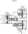
- FIG. 2 through FIG. 10 are plan views showing stages in a method of operating a distribution system according to an embodiment of the present invention.
- FIG. 11 through FIG. 13 are plan views showing stages in a method of operating a distribution system according to another embodiment of the present invention.
- FIG. 14 through FIG. 16 are plan views showing stages in a method of operating a distribution system according to another embodiment of the present invention.
- FIG. 1 is a plan view of a distribution system according to an embodiment of the present invention. As shown in FIG. 1 , this distribution system includes a plate 20 , a first transfer assembly 30 for transferring substrates 1 through 12 loaded on plate 20 to a conveyer 70 , and a distribution assembly 40 for distributing the substrates delivered by conveyer 70 to a first testing assembly 50 and a second testing assembly 60 .
- Plate 20 is formed in a rectangular shape in one example, similar to a conveyer shape, and the plurality of substrates 1 through 12 are loaded thereon. It is noted that plate 20 may be formed to have various shapes.
- the plurality of substrates 1 through 12 are separated from a large-size panel (i.e., the motherboard) by the scribing process, and each substrate corresponds to a cell, which corresponds to a liquid crystal display (LCD) panel.
- LCD liquid crystal display
- First transfer assembly 30 includes a vacuum pad 31 for engaging the substrates via suction in a vacuum state, and a transfer part 35 for moving vacuum pad 31 horizontally, vertically, and rotatably.
- vacuum pad 31 is configured so that its suction portions are each capable of engaging and not engaging according to the scale of the substrate.
- Transfer part 35 includes a pair of horizontal arms 32 parallel to each other, an X-axis slider 33 supported by horizontal arms 32 and movable in the X-direction, and a Y-axis slider 34 associated with X-axis slider 33 and movable in the Y-direction along the X-axis slider 33 .
- Y-axis slider 34 is rotatably associated with vacuum pad 31 and may rotate vacuum pad 31 by about 360 degrees. Vacuum pad 31 may be moved in horizontal, vertical, and rotatable directions substantially simultaneously in one embodiment.
- Distribution assembly 40 includes a first sub-conveyer 41 and a second sub-conveyer 42 which are connected by a connection bar 43 .
- first sub-conveyer 41 and second sub-conveyer 42 are statically positioned to be a set distance from one another.
- Sub-conveyers 41 and 42 can thus move in parallel in the Y-direction along a common vertical axis, reciprocating between receiving a substrate (when a sub-conveyer inlet is inline with or corresponds to the outlet of conveyer 70 ) and delivering a substrate (when a sub-conveyer outlet is inline with or corresponds to the inlet of a testing conveyer 51 or 61 .)
- First testing assembly 50 includes a first testing conveyer 51 for receiving the substrate from first sub-conveyer 41 , a first testing part 57 which is positioned adjacent to an outlet of first testing conveyer 51 for checking the state of (or otherwise processing) the substrate, and a second transfer assembly 50 for transferring the substrate from first testing conveyer 51 to first testing part 57 .
- the outlet of conveyer 70 corresponds to (i.e., is inline with) an inlet of one of the first and second sub-conveyers 41 and 42 .
- the outlet of one of the first and second sub-conveyers 41 and 42 corresponds to (i.e., is inline with) the inlet of one of the first and second testing assemblies 50 and 60 .
- the inlet of second sub-conveyer 42 corresponds to the outlet of conveyer 70 .
- the inlet of first sub-conveyer 41 corresponds to the outlet of conveyer 70 .
- conveyer 70 , first and second sub-conveyers 41 and 42 , and first and second testing conveyers 51 and 61 are belt type conveyers or roller type conveyers and individually include arrangement elements 79 , 48 , 49 , 59 , and 69 .
- Arrangement elements 79 , 48 , 49 , 59 , and 69 each include a plurality of pushers disposed at substantially the sides and outlet of each conveyer. The pushers arrange the substrate on the conveyer by pushing it.
- a substrate reversing mechanism may be further included in this distribution system. That is, when a lower substrate is delivered to the distribution system in a way that it is directed upward, reversion of the lower substrate is necessary so that the first and second testing assemblies 50 and 60 may check the state of the substrate. At this time, the substrate reversing mechanism performs such a reversion.
- first transferring assembly 30 is positioned over and ready to transfer substrate 1 ( FIG. 1 ).
- the outlet of second sub-conveyer 42 corresponds to the inlet of second testing conveyer 61
- the inlet of first sub-conveyer 41 corresponds to the outlet of conveyer 70 .
- first transfer assembly 30 engages substrate 1 using vacuum pad 31 and then transfers substrate 1 to conveyer 70 .
- First substrate 1 is then released from the vacuum suction state, thereby being disposed on conveyer 70 .
- Arrangement elements 79 of conveyer 70 suitably adjust the position of substrate 1 on conveyer 70 .
- substrate 1 is transferred from conveyer 70 to first sub-conveyer 41 when the outlet of the conveyer 70 corresponds to inlet of first sub-conveyer 41 .
- first transfer assembly 30 is positioned over and ready to transfer second substrate 2 .
- first sub-conveyer 41 After arrangement elements 48 of first sub-conveyer 41 suitably adjust the position of first substrate 1 on first sub-conveyer 41 , distribution assembly 40 is transferred in the downward Y-direction so that the outlet of first sub-conveyer 41 corresponds to the inlet of first testing conveyer 51 while the inlet of second sub-conveyer 42 corresponds to the outlet of conveyer 70 .
- This is to directly place substrate 1 from first sub-conveyer 41 in line with first testing conveyer 51 without adjusting the position of substrate 1 .
- Substrate 1 then moves from the inlet portion of first sub-conveyer 41 to the outlet portion.
- first transfer assembly 30 suctions substrate 2 using vacuum pad 31 , and then transfers substrate 2 to conveyer 70 .
- Substrate 2 is then released from the vacuum suction state, thereby being disposed on conveyer 70 .
- second transfer assembly 56 transfers substrate 1 from first testing conveyer 51 to first testing part 57 .
- second transfer assembly 56 vacuum suctions first substrate 1 using vacuum pad 55 , and then transfers substrate 1 to first testing part 57 for processing (e.g., testing). Substrate 1 is then released from the vacuum suction state, thereby being disposed on first testing part 57 .
- Second transfer assembly 56 includes vacuum pad 55 for performing vacuum suction/engagement of the substrate, and transfer part 58 for transferring vacuum pad 55 horizontally, vertically, and rotatably.
- Transfer part 58 includes two horizontal arms 52 parallel to each other, the X-axis slider 53 supported by horizontal arms 52 and movable in the X-direction, and the Y-axis slider 54 associated with the X-axis slider 53 and movable along the X-axis slider 53 in the Y-direction.
- the Y-axis slider 54 is rotatably associated with vacuum pad 55 and may rotate vacuum pad 55 by about 360 degrees. Vacuum pad 55 may be moved in horizontal, vertical, and rotatable directions substantially simultaneously in one embodiment.
- distribution assembly 40 is transferred in the upward Y-direction so that the outlet of second sub-conveyer 42 corresponds to the inlet of second testing conveyer 61 while the inlet of first sub-conveyer 41 corresponds to the outlet of conveyer 70 .
- first transfer assembly 30 suctions the substrate 3 using vacuum pad 31 , and then transfers it to conveyer 70 .
- Substrate 3 is then released from the vacuum suction/engagement state, thereby being disposed on conveyer 70 .
- first testing part 57 checks the state of substrate 1 , namely, whether the substrate is cut by the preceding scribing process according to specifications and whether any crack exists in the substrate.
- substrate 2 is horizontally transferred to second testing conveyer 61 by second sub-conveyer 42 .
- substrate 3 is transferred from conveyer 70 to first sub-conveyer 41 when the outlet of conveyer 70 corresponds to the inlet of first sub-conveyer 41 .
- first transfer assembly 30 is positioned over and ready to transfer substrate 4 .
- Third transfer assembly 66 includes vacuum pad 65 for performing vacuum suction/engagement of the substrate, and transfer part 68 for transferring vacuum pad 65 horizontally, vertically, and rotatably.
- Transfer part 68 includes two horizontal arms 62 parallel to each other, X-axis slider 63 supported by horizontal arms 62 and movable in the X-direction, and Y-axis slider 64 associated with X-axis slider 63 and vertically movable in the Y-direction along X-axis slider 63 .
- Y-axis slider 64 is rotatably associated with vacuum pad 65 and may rotate vacuum pad 63 by about 360 degrees. Vacuum pad 63 may be moved in horizontal, vertical, and rotatable directions substantially simultaneously in one embodiment.
- distribution assembly 40 is transferred in the downward Y-direction so that the outlet of first sub-conveyer 41 corresponds to the inlet of first testing conveyer 51 while the inlet of second sub-conveyer 42 corresponds to the outlet of conveyer 70 .
- first transfer assembly 30 suctions/engages substrate 4 using vacuum pad 31 , and then transfers substrate 4 to conveyer 70 . Substrate 4 is then released from the vacuum suction/engagement state, thereby being disposed on conveyer 70 .
- second testing part 67 checks the state of substrate 2 similar to that which was done on substrate 1 .
- substrate 3 is horizontally transferred to first testing conveyer 51 by first sub-conveyer 41 .
- substrate 4 is transferred from conveyer 70 to second sub-conveyer 42 when the outlet of conveyer 70 corresponds to the inlet of second sub-conveyer 42 .
- all of the substrates 5 through 8 of the center column may be optionally transferred forward to shorten a movement distance of first transfer assembly 30 .
- first transfer assembly 30 is positioned over and ready to transfer substrate 5 .
- the operation of the distribution system continues in a way that the above-mentioned steps are repeated for transferring and processing substrates 5 through 8 .
- the substrates supplied from one line are distributed into two lines by distribution assembly 40 , so that the tact time is reduced.
- the transfer assembly directly supplies the substrates to two lines, similar to first testing assembly 50 and second assembly 60 , the transfer distance of the transfer assembly in total is relatively longer and thus the tact time increases.
- the transfer assembly does not directly supply the substrates to first testing assembly 50 and second testing assembly 60 , and the substrates are distributed into two lines by the vertical reciprocating motion of distribution assembly 40 . Accordingly, the transfer distance of the transfer assembly is shortened and the tact time is thus reduced.
- the time it takes to transfer vacuum pad 31 downwardly is 1 second
- the time it takes to perform the vacuum engagement between vacuum pad 31 and the substrate is 0.4 second
- the time it takes to return vacuum pad 31 to the original position is 1 second. Accordingly, the vertical motion time of first transfer assembly 30 to take one substrate totals about 2.4 seconds.
- a total transfer time of vacuum pad 31 is determined by a horizontal transfer time since it is larger than a rotary transfer time.
- the transfer time of vacuum pad 31 of the first transfer assembly 30 is 2.0 seconds when the substrate is 19 inches, while being 2.7 seconds when the substrate is 46 inches. Accordingly, the time for one reciprocating motion of first assembly 30 between a substrate receiving position and a substrate delivering position becomes about 4.0 seconds (for the 19-inch substrate) or about 5.4 seconds (for the 46-inch substrate).
- the time it takes to vertically transfer first transfer assembly 30 for supplying the substrate to conveyer 70 is about 2.2 seconds which is the sum of a downward transfer time of vacuum pad 31 (1 second), a vacuum releasing time between vacuum pad 31 and the substrate (0.2 second), and an upward transfer time of vacuum pad 31 (1 second).
- the total tact time of the first transfer assembly 30 is about 8.6 seconds (for the 19-inch substrate), or about 10 seconds (for the 49-inch substrate).
- the substrates may be transferred from the inlets of first sub-conveyer 41 and second sub-conveyer 42 to the outlets thereof.
- the time it takes to transfer the substrate from the inlet to the outlet of first sub-conveyer 41 or second sub-conveyer 42 is about 9.3 seconds
- the time it takes to transfer distribution assembly 40 in the Y-direction is about 4.6 seconds. Accordingly, the tact time of distribution assembly 40 is determined by the substrate transfer time on first sub-conveyer 41 and second sub-conveyer 42 since this time is larger than the vertical transfer time of distribution assembly 40 .
- the tact time of the distribution system becomes about 9.3 seconds or about 10 seconds on the basis of the tact time of first transfer assembly 30 (8.6 seconds or 10 seconds) and the tact time of distribution assembly 40 (9.3 seconds). Accordingly, the tact time of the distribution system substantially corresponds to the tact time of the scribing process since the tact time of the scribing process is about 10 seconds when the substrate is 17 inches or about 12 seconds when the substrate is 19 inches, thereby reducing bottleneck created in the distribution system.
- FIG. 11 through FIG. 13 Another distribution system according to a second embodiment of the present invention will now be described with reference to FIG. 11 through FIG. 13 .
- the second embodiment is differentiated from the first embodiment in that two substrates are transferred at the same time so as to shorten by a half the tact time of first transfer assembly 30 .
- a plurality of substrates 1 through 36 are disposed on conveyer-shaped plate 20 (e.g., rectangular). Substrates 1 through 36 are separated from a large-size panel (called a motherboard) by the scribing process. Substrates 1 through 6 are systematically arranged at the rightmost column, and substrates 7 through 12 are systematically arranged at the next column.
- conveyer-shaped plate 20 e.g., rectangular
- Substrates 1 through 36 are separated from a large-size panel (called a motherboard) by the scribing process.
- Substrates 1 through 6 are systematically arranged at the rightmost column, and substrates 7 through 12 are systematically arranged at the next column.
- first transfer assembly 30 is initially transferred on substrates 1 and 7 .
- the outlet of second sub-conveyer 42 corresponds to the inlet of second testing conveyer 61 while the inlet of first sub-conveyer 41 corresponds to the outlet of conveyer 70 .
- first transfer assembly 30 simultaneously suction engages two substrates 1 and 7 using vacuum pad 31 , and transfers them to conveyer 70 .
- Substrate 1 is then released from the vacuum suction/engagement state by the partial operation of vacuum pad 31 (i.e., suction holding only substrate 1 is released), thereby being disposed on conveyer 70 .
- arrangement elements 79 of conveyer 70 suitably adjust the position of substrate 1 on conveyer 70 .
- substrate 1 is transferred from conveyer 70 to first sub-conveyer 41 when the inlet of first sub-conveyer 41 corresponds to the outlet of conveyer 70 .
- first transfer assembly 30 is positioned over and ready to transfer substrates 2 and 8 .
- distribution assembly 40 is transferred in the downward Y-direction so that the outlet of first sub-conveyer 41 corresponds to the inlet of first testing conveyer 51 while the inlet of second sub-conveyer 42 corresponds to the outlet of conveyer 70 . This is to directly place substrate 1 from first sub-conveyer 41 inline with first testing conveyer 51 without adjusting the position of substrate 1 .
- substrate 1 is horizontally transferred onto first testing conveyer 51 from first sub-conveyer 41 .
- substrate 7 is transferred from conveyer 70 to second sub-conveyer 42 when the outlet of conveyer 70 corresponds to the inlet of second sub-conveyer 42 .
- first transfer assembly 30 suction engages substrates 2 and 8 ( FIG. 12 ) using vacuum pad 31 , and then transfers them to conveyer 70 .
- Substrate 2 is then released from the vacuum suction/engagement state by the partial operation of vacuum pad 31 (i.e., suction holding only substrate 2 is released), thereby being disposed on conveyer 70 .
- first transfer assembly 30 takes two substrates at the same time and then transfers them onto conveyer 70 , thereby shortening the tact time of first transfer assembly 30 by about half.
- Still another distribution system according to a third embodiment of the present invention will now be described with reference to FIG. 14 through FIG. 16 .
- the third embodiment is differentiated from the first and second embodiments in that vacuum pad 31 of first transfer assembly 30 takes two substrates at the same time and turns by about 90 degrees before being transferred, thereby shortening the tact time of first transfer assembly 30 by about half.
- a plurality of substrates 1 through 24 are disposed on plate 20 .
- Substrates 1 through 24 are separated from a large-size panel called a motherboard by the scribing process.
- Substrates 1 through 4 are systematically arranged at the rightmost column, substrates 5 through 8 are systematically arranged at the next column, and so on.
- first transfer assembly 30 is initially positioned over and ready to transfer on substrates 1 and 2 .
- first transfer assembly 30 simultaneously suction engages substrates 1 and 2 using vacuum pad 31 , and transfers them to conveyer 70 after rotating vacuum pad 31 by about 90 degrees.
- the transfer distance between first transfer assembly 30 and conveyer 70 is shortened and the tact time of the transfer assembly is also shortened.
- substrate 1 is released from the vacuum suction/engagement state by the partial operation of vacuum pad 31 , (i.e., suction holding only substrate 1 is released) thereby being disposed on conveyer 70 .
- substrate 1 is transferred from conveyer 70 to first sub-conveyer 41 when the inlet of first sub-conveyer 41 corresponds to the outlet of conveyer 70 .
- substrate 2 is released from the vacuum suction/engagement state by the partial operation of vacuum pad 31 (i.e., suction holding only substrate 2 is released), thereby being disposed on conveyer 70 .
- the time it takes to transfer the substrate using first transfer assembly 30 is about 8.6 seconds.
- the time it takes to suitably arrange the substrate on conveyer 70 is about 1 second.
- the time it takes to transfer substrate 1 from conveyer 70 to distribution assembly 40 is about 3.3 seconds.
- the time it takes to vertically transfer first transfer assembly 30 for supplying substrate 7 on conveyer 70 is about 2.2 seconds which is the sum of a downward transfer time of vacuum pad 31 (about 1 second), a vacuum releasing time between vacuum pad 31 and substrate 7 (about 0.2 second), and an upward transfer time of vacuum pad 31 (about 1 second).
- the total tact time of first transfer assembly 30 is about 7.5 seconds (calculated by 8.6+2.2+1.0+3.3/2 seconds).
- a front portion and a rear potion of vacuum pad 31 are capable of operating separately to transfer two substrates at the same time.
- the distribution assembly including two sub-conveyers efficiently distributes the substrates supplied from one line into two lines, thereby shortening the tact time.
- the transfer assembly of the present invention transfers the substrates by vertical transfer and rotary motion, thereby shortening the tact time.
Landscapes
- Physics & Mathematics (AREA)
- Nonlinear Science (AREA)
- General Physics & Mathematics (AREA)
- Crystallography & Structural Chemistry (AREA)
- Chemical & Material Sciences (AREA)
- Optics & Photonics (AREA)
- Manufacturing & Machinery (AREA)
- Engineering & Computer Science (AREA)
- Container, Conveyance, Adherence, Positioning, Of Wafer (AREA)
- Branching, Merging, And Special Transfer Between Conveyors (AREA)
- Intermediate Stations On Conveyors (AREA)
- Special Conveying (AREA)
- Liquid Crystal (AREA)
Abstract
Description
Claims (19)
Applications Claiming Priority (2)
| Application Number | Priority Date | Filing Date | Title |
|---|---|---|---|
| KR1020040024070A KR101006449B1 (en) | 2004-04-08 | 2004-04-08 | Distribution System for Liquid Crystal Display Manufacturing |
| KR10-2004-0024070 | 2004-04-08 |
Publications (2)
| Publication Number | Publication Date |
|---|---|
| US20050274588A1 US20050274588A1 (en) | 2005-12-15 |
| US7347312B2 true US7347312B2 (en) | 2008-03-25 |
Family
ID=35459339
Family Applications (1)
| Application Number | Title | Priority Date | Filing Date |
|---|---|---|---|
| US11/100,992 Expired - Fee Related US7347312B2 (en) | 2004-04-08 | 2005-04-06 | Distribution system and method of operating the same |
Country Status (3)
| Country | Link |
|---|---|
| US (1) | US7347312B2 (en) |
| KR (1) | KR101006449B1 (en) |
| TW (1) | TW200602728A (en) |
Cited By (6)
| Publication number | Priority date | Publication date | Assignee | Title |
|---|---|---|---|---|
| US20080289930A1 (en) * | 2007-05-14 | 2008-11-27 | Manfred Fischer | Apparatus for displacing units relative to a transport track |
| US20090200141A1 (en) * | 2006-03-14 | 2009-08-13 | Shigekazu Noda | Panel Sorting Method And Panel Sorting Device |
| US20110005897A1 (en) * | 2007-06-13 | 2011-01-13 | Schaefer Gerhard | Tilting and rotating station for use in an automated order-picking system |
| US20120118701A1 (en) * | 2009-07-30 | 2012-05-17 | Sidel Participations | Method for grouping products together with a view to case packing same |
| US20160304291A1 (en) * | 2013-12-05 | 2016-10-20 | Gea Lyophil Gmbh | Unloading device featuring vacuum suction |
| US10327366B2 (en) * | 2015-01-30 | 2019-06-18 | Panasonic Intellectual Property Management Co., Ltd. | Conveyance robot apparatus |
Families Citing this family (3)
| Publication number | Priority date | Publication date | Assignee | Title |
|---|---|---|---|---|
| CN102092575B (en) * | 2010-11-23 | 2013-08-21 | 深圳市宇顺电子股份有限公司 | Working method of multifunctional streamlined production line |
| CH709797A1 (en) * | 2014-06-19 | 2015-12-31 | Texa Ag | Apparatus and method for feeding elongate, at least approximately hollow-cylindrical product units to Abpackeinheiten. |
| CN113963788B (en) * | 2020-07-20 | 2025-08-05 | 江苏雷镈智能科技有限公司 | Sample tube dispensing device and dispensing method |
Citations (16)
| Publication number | Priority date | Publication date | Assignee | Title |
|---|---|---|---|---|
| US4287980A (en) * | 1979-09-21 | 1981-09-08 | E. P. Remy Et Cie. | Device for distributing containers into several rows and machine using such a device |
| US4493939A (en) * | 1983-10-31 | 1985-01-15 | Varo, Inc. | Method and apparatus for fabricating a thermoelectric array |
| US4678172A (en) * | 1985-12-27 | 1987-07-07 | Custom-Bilt Machinery, Inc. | High speed on-line reshingling of printed products |
| US4697318A (en) * | 1985-11-26 | 1987-10-06 | The J. L. Wickham Company, Incorporated | Adaptable machining system |
| US4753103A (en) * | 1983-10-04 | 1988-06-28 | L. Schuler Gmbh | Arrangement for the feeding of sheet-metal blanks to the drawing stage of a transfer press |
| US5024315A (en) * | 1985-08-19 | 1991-06-18 | O-I Neg Tv Products, Inc. | Method of distributing workpieces between a conveyor and workstations |
| US5269646A (en) * | 1989-05-09 | 1993-12-14 | Focke & Co. (Gmbh & Co.) | Process and installation for the rearrangement of articles palletised according to sorts to form groups of specific sort composition |
| US5427252A (en) * | 1991-08-28 | 1995-06-27 | Westinghouse Electric Corporation | Automated system and method for sorting and stacking reusable cartons |
| US5520107A (en) * | 1994-01-07 | 1996-05-28 | Societe D'exploitation Des Machines Dubuit | Printing machine for printing objects liable to be stacked |
| US5696688A (en) * | 1996-01-29 | 1997-12-09 | Newell Operating Company | Method and apparatus for welding handle studs to cooking vessels |
| US6643917B1 (en) * | 2000-01-19 | 2003-11-11 | Delaware Capital Formation | Redundant system for assembly of electronic components to substrates |
| US6786328B2 (en) * | 2002-12-20 | 2004-09-07 | Ferag Ag | Method and device for transforming a supply stream of flat stream elements, in particular a supply stream in which the elements are conveyed overlapping one another |
| US6840176B1 (en) * | 2003-12-02 | 2005-01-11 | Creo Il. Ltd. | CTP systems having at least one multi-cassette unit and methods for loading plates |
| US7000755B2 (en) * | 2000-01-14 | 2006-02-21 | Fps Food Processing Systems, B.V. | Apparatus for repositioning product while maintaining forward conveying speed |
| US7047710B2 (en) * | 2003-03-26 | 2006-05-23 | Logistik + Informatik Gmbh | Apparatus for depositing a packing unit at a desired position on a load carrier |
| US7077262B2 (en) * | 1999-05-21 | 2006-07-18 | Matsushita Electric Industrial Co., Ltd | Device and method for conveying and holding plate-like member |
Family Cites Families (3)
| Publication number | Priority date | Publication date | Assignee | Title |
|---|---|---|---|---|
| KR100426790B1 (en) * | 2001-08-02 | 2004-04-13 | 김영호 | Manufacturing method of condensation material for breeding mushroom |
| JP2003267545A (en) | 2002-03-14 | 2003-09-25 | Okamura Corp | Device for turning direction of conveying load |
| KR200311421Y1 (en) | 2002-12-26 | 2003-04-30 | 주식회사 성직 | Leaf supplying device of sheet manufacturing machine for LCD backlight |
-
2004
- 2004-04-08 KR KR1020040024070A patent/KR101006449B1/en not_active Expired - Fee Related
-
2005
- 2005-04-06 US US11/100,992 patent/US7347312B2/en not_active Expired - Fee Related
- 2005-04-07 TW TW094110994A patent/TW200602728A/en unknown
Patent Citations (17)
| Publication number | Priority date | Publication date | Assignee | Title |
|---|---|---|---|---|
| US4287980A (en) * | 1979-09-21 | 1981-09-08 | E. P. Remy Et Cie. | Device for distributing containers into several rows and machine using such a device |
| US4753103A (en) * | 1983-10-04 | 1988-06-28 | L. Schuler Gmbh | Arrangement for the feeding of sheet-metal blanks to the drawing stage of a transfer press |
| US4493939A (en) * | 1983-10-31 | 1985-01-15 | Varo, Inc. | Method and apparatus for fabricating a thermoelectric array |
| US5024315A (en) * | 1985-08-19 | 1991-06-18 | O-I Neg Tv Products, Inc. | Method of distributing workpieces between a conveyor and workstations |
| US4697318A (en) * | 1985-11-26 | 1987-10-06 | The J. L. Wickham Company, Incorporated | Adaptable machining system |
| US4678172A (en) * | 1985-12-27 | 1987-07-07 | Custom-Bilt Machinery, Inc. | High speed on-line reshingling of printed products |
| US5269646A (en) * | 1989-05-09 | 1993-12-14 | Focke & Co. (Gmbh & Co.) | Process and installation for the rearrangement of articles palletised according to sorts to form groups of specific sort composition |
| US5427252A (en) * | 1991-08-28 | 1995-06-27 | Westinghouse Electric Corporation | Automated system and method for sorting and stacking reusable cartons |
| US5520107A (en) * | 1994-01-07 | 1996-05-28 | Societe D'exploitation Des Machines Dubuit | Printing machine for printing objects liable to be stacked |
| US5696688A (en) * | 1996-01-29 | 1997-12-09 | Newell Operating Company | Method and apparatus for welding handle studs to cooking vessels |
| US7077262B2 (en) * | 1999-05-21 | 2006-07-18 | Matsushita Electric Industrial Co., Ltd | Device and method for conveying and holding plate-like member |
| US7000755B2 (en) * | 2000-01-14 | 2006-02-21 | Fps Food Processing Systems, B.V. | Apparatus for repositioning product while maintaining forward conveying speed |
| US6643917B1 (en) * | 2000-01-19 | 2003-11-11 | Delaware Capital Formation | Redundant system for assembly of electronic components to substrates |
| US7032304B2 (en) * | 2000-01-19 | 2006-04-25 | Delaware Capital Formation | Method for conveying printed circuit boards |
| US6786328B2 (en) * | 2002-12-20 | 2004-09-07 | Ferag Ag | Method and device for transforming a supply stream of flat stream elements, in particular a supply stream in which the elements are conveyed overlapping one another |
| US7047710B2 (en) * | 2003-03-26 | 2006-05-23 | Logistik + Informatik Gmbh | Apparatus for depositing a packing unit at a desired position on a load carrier |
| US6840176B1 (en) * | 2003-12-02 | 2005-01-11 | Creo Il. Ltd. | CTP systems having at least one multi-cassette unit and methods for loading plates |
Cited By (11)
| Publication number | Priority date | Publication date | Assignee | Title |
|---|---|---|---|---|
| US20090200141A1 (en) * | 2006-03-14 | 2009-08-13 | Shigekazu Noda | Panel Sorting Method And Panel Sorting Device |
| US8118155B2 (en) * | 2006-03-14 | 2012-02-21 | Komatsu Ltd. | Panel sorting method and panel sorting device |
| US20080289930A1 (en) * | 2007-05-14 | 2008-11-27 | Manfred Fischer | Apparatus for displacing units relative to a transport track |
| US7997401B2 (en) * | 2007-05-14 | 2011-08-16 | Krones Ag | Apparatus for displacing units relative to a transport track |
| US20110005897A1 (en) * | 2007-06-13 | 2011-01-13 | Schaefer Gerhard | Tilting and rotating station for use in an automated order-picking system |
| US8172071B2 (en) * | 2007-06-13 | 2012-05-08 | Ssi Schafer Noell Gmbh Lager-Und Systemtechnik | Tilting and rotating station for use in an automated order-picking system |
| US20120118701A1 (en) * | 2009-07-30 | 2012-05-17 | Sidel Participations | Method for grouping products together with a view to case packing same |
| US9132970B2 (en) * | 2009-07-30 | 2015-09-15 | C.E.R.M.E.X. Constructions Etudes Et Recherches De Materiels Pour L'emballage D'expedition | Method for grouping products together with a view to case packing same |
| US20160304291A1 (en) * | 2013-12-05 | 2016-10-20 | Gea Lyophil Gmbh | Unloading device featuring vacuum suction |
| US10005621B2 (en) * | 2013-12-05 | 2018-06-26 | Gea Lyophil Gmbh | Unloading device featuring vacuum suction |
| US10327366B2 (en) * | 2015-01-30 | 2019-06-18 | Panasonic Intellectual Property Management Co., Ltd. | Conveyance robot apparatus |
Also Published As
| Publication number | Publication date |
|---|---|
| TW200602728A (en) | 2006-01-16 |
| KR20050098630A (en) | 2005-10-12 |
| US20050274588A1 (en) | 2005-12-15 |
| KR101006449B1 (en) | 2011-01-06 |
Similar Documents
| Publication | Publication Date | Title |
|---|---|---|
| US7637799B2 (en) | Substrate production apparatus for producing a substrate for a display device | |
| JP4563351B2 (en) | Method for cutting liquid crystal display panel and method for manufacturing liquid crystal display panel using the same | |
| CN100429567C (en) | Device for manufacturing liquid crystal display and method for using same | |
| US7347312B2 (en) | Distribution system and method of operating the same | |
| CN1991491B (en) | Liquid crystal display panel cutting method and method of manufacturing liquid crystal display panel using the method | |
| US6953073B2 (en) | Apparatus and method for manufacturing liquid crystal display devices, method for using the apparatus, and device produced by the method | |
| US7714978B2 (en) | Method for cutting liquid crystal display panel and method for fabricating liquid crystal display panel using the same | |
| KR101730553B1 (en) | Apparatus for conveying substrate | |
| JP2003295144A (en) | Process line of liquid crystal display device and manufacturing method using the same | |
| KR100841630B1 (en) | Integrated liquid crystal display device manufacturing line and liquid crystal display device manufacturing method using the same | |
| KR101000086B1 (en) | Substrate processing apparatus and substrate processing method of cluster apparatus | |
| US20100089961A1 (en) | Apparatus and method of cutting liquid crystal display device | |
| US7807214B2 (en) | Dispensing apparatus for liquid crystal display panel and dispensing method using the same | |
| KR100821185B1 (en) | Substrate Cutting System and Method | |
| KR20110102678A (en) | Substrate Storage Cassette | |
| CN100416360C (en) | Manufacturing method of liquid crystal display device | |
| KR101801397B1 (en) | Apparatus fabrication of liquid crystal display device | |
| KR101003580B1 (en) | Board Supply Device | |
| KR101034713B1 (en) | Photoresist Process System | |
| KR101308749B1 (en) | Method for fabricating liquid crystal display device | |
| JP6163858B2 (en) | Rubbing apparatus and method for manufacturing liquid crystal display device | |
| KR20170003045A (en) | Apparatus of Photo Alignment | |
| KR20060058890A (en) | Board storage cassette | |
| CN110346951A (en) | Substrate support pedestal | |
| KR20050121365A (en) | Apparatus for transferring of cassette |
Legal Events
| Date | Code | Title | Description |
|---|---|---|---|
| AS | Assignment |
Owner name: SAMSUNG ELECTRONICS CO., LTD., KOREA, REPUBLIC OF Free format text: ASSIGNMENT OF ASSIGNORS INTEREST;ASSIGNORS:HAN, JAE-YONG;CHEONG, JUN-HO;JUNG, BYUNG-WOO;REEL/FRAME:016912/0366 Effective date: 20050727 |
|
| FEPP | Fee payment procedure |
Free format text: PAYOR NUMBER ASSIGNED (ORIGINAL EVENT CODE: ASPN); ENTITY STATUS OF PATENT OWNER: LARGE ENTITY |
|
| FEPP | Fee payment procedure |
Free format text: PAYER NUMBER DE-ASSIGNED (ORIGINAL EVENT CODE: RMPN); ENTITY STATUS OF PATENT OWNER: LARGE ENTITY Free format text: PAYOR NUMBER ASSIGNED (ORIGINAL EVENT CODE: ASPN); ENTITY STATUS OF PATENT OWNER: LARGE ENTITY |
|
| FPAY | Fee payment |
Year of fee payment: 4 |
|
| AS | Assignment |
Owner name: SAMSUNG DISPLAY CO., LTD., KOREA, REPUBLIC OF Free format text: ASSIGNMENT OF ASSIGNORS INTEREST;ASSIGNOR:SAMSUNG ELECTRONICS CO., LTD.;REEL/FRAME:029008/0389 Effective date: 20120904 |
|
| REMI | Maintenance fee reminder mailed | ||
| LAPS | Lapse for failure to pay maintenance fees | ||
| STCH | Information on status: patent discontinuation |
Free format text: PATENT EXPIRED DUE TO NONPAYMENT OF MAINTENANCE FEES UNDER 37 CFR 1.362 |
|
| STCH | Information on status: patent discontinuation |
Free format text: PATENT EXPIRED DUE TO NONPAYMENT OF MAINTENANCE FEES UNDER 37 CFR 1.362 |
|
| FP | Lapsed due to failure to pay maintenance fee |
Effective date: 20160325 |