US734603A - Fireproof casing. - Google Patents
Fireproof casing. Download PDFInfo
- Publication number
- US734603A US734603A US14288403A US1903142884A US734603A US 734603 A US734603 A US 734603A US 14288403 A US14288403 A US 14288403A US 1903142884 A US1903142884 A US 1903142884A US 734603 A US734603 A US 734603A
- Authority
- US
- United States
- Prior art keywords
- shutters
- shaft
- casing
- posts
- rod
- Prior art date
- Legal status (The legal status is an assumption and is not a legal conclusion. Google has not performed a legal analysis and makes no representation as to the accuracy of the status listed.)
- Expired - Lifetime
Links
- 241001077898 Melanthera Species 0.000 description 4
- 238000005452 bending Methods 0.000 description 2
- 238000010276 construction Methods 0.000 description 2
- CWYNVVGOOAEACU-UHFFFAOYSA-N Fe2+ Chemical compound [Fe+2] CWYNVVGOOAEACU-UHFFFAOYSA-N 0.000 description 1
- 229910000754 Wrought iron Inorganic materials 0.000 description 1
- 230000008602 contraction Effects 0.000 description 1
- 230000002431 foraging effect Effects 0.000 description 1
- 235000000396 iron Nutrition 0.000 description 1
- 238000004519 manufacturing process Methods 0.000 description 1
- 239000002184 metal Substances 0.000 description 1
- 229910052751 metal Inorganic materials 0.000 description 1
- 239000008400 supply water Substances 0.000 description 1
Images


Classifications
-
- F—MECHANICAL ENGINEERING; LIGHTING; HEATING; WEAPONS; BLASTING
- F24—HEATING; RANGES; VENTILATING
- F24F—AIR-CONDITIONING; AIR-HUMIDIFICATION; VENTILATION; USE OF AIR CURRENTS FOR SCREENING
- F24F13/00—Details common to, or for air-conditioning, air-humidification, ventilation or use of air currents for screening
- F24F13/08—Air-flow control members, e.g. louvres, grilles, flaps or guide plates
- F24F13/10—Air-flow control members, e.g. louvres, grilles, flaps or guide plates movable, e.g. dampers
- F24F13/14—Air-flow control members, e.g. louvres, grilles, flaps or guide plates movable, e.g. dampers built up of tilting members, e.g. louvre
- F24F13/15—Air-flow control members, e.g. louvres, grilles, flaps or guide plates movable, e.g. dampers built up of tilting members, e.g. louvre with parallel simultaneously tiltable lamellae
Definitions
- My invention relates to certain new and useful improvements in elevatorcasi'ngs, and
- ⁇ has for its object to produce a casing which under normal conditions is kopen for the ad- ⁇ mission of light and air to the shaft and which may be closed simultaneously for all the iioors ofV a building to make the casing iireproof in case a fire should occur on any floor of the building, thereby preventing the fire from spreading to the other floors of the building by being drawn-up through the elevator-shaft and at the same time allowing persons who may be on the upper floors of the building to be carried down in safety by the elevator.
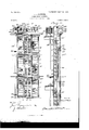
- Figure l is a Vertical elevation of myinventiou as applied to an elevator-casing, showing three'floors of av building.
- Fig. 2 is a vertical section showing the means for operating the shutters.
- Fig. 3 is a detached View of the telescoping cornice and foot-plates for thespportingposts of the casing, showing the shutters closed and in operative relation to thecornic'e and foot-plates.
- Fig. 4 isla detail viewshowing the ymeans by which the shutters are mounted in their supporting-posts.
- Fig. 5 is a view similar to Fig. 4,taken at right angles thereto.
- Fig. 4 is a view similar to Fig. 4,taken at right angles thereto.
- FIG. 6 is a transversehorizontal section showing the means fattaching the opl erating-pinionand the shutters together and also showing how the shutters'are pivoted in their supports.
- Fig. 7 is a view similar to Fig. 2, but showing a slightly-modified form of the operating mechanism.
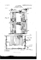
- Fig; Si s a side elevation of my casing when used in connection with a stairway.
- Fig. 9 is aview similar to Fig. S, taken at right angles thereto, showing the doors at each floor.
- Fig. l0 is a section view through the casing.
- l is a casing extending through the several floors of a building provided 'with doors 2 2 2, one on each door.
- the casing consists of a series of posts 3 3, in which are pivoted a series of shutters 4.
- the posts 3 are shown in section in Fig. 6,' fromwhich it will be seen that these posts are in the form of channel-irons, and on the interior edges of the side walls of these posts I provide slots 5, the bottoms of which are of semicircular'form and which are closed and in which thestems areadapted to rotatel when theshutters are opened or closed.
- the shutters are made from plates "of sheet'metal and bent in the form'shown best in' Figs. 3 and 7, the stems of the shutters being preferably square in cross-section and formed by bending up a portion of the blank from which the shutters are made, suitable cuts being made in the blank 'on each side for this purpose.
- the stems of the shutters being preferably square in cross-section and formed by bending up a portion of the blank from which the shutters are made, suitable cuts being made in the blank 'on each side for this purpose.
- Through 'thecenter of each shutter-blank I forma longitudinal stiff- -ening-rib 55 by'bending out of the central portion of the blank a V-shaped'groove parallel with the longitudinal axis of the blank.
- the rib extends also to the extremity of each extending portionofthe' blank from which the stemsy are made* and forms two-sides of lthe square stems and insures the axial alinement of the stems.
- These squareA stems 9 project into the notches formed by the' slots 5 and '7.
- the stems of the shutters project infrom the opposite 'side walls ofthe channel-'irons and are united together by a gear l0, having square stems 11, which are inserted inthe openings formedtin-the stems 9 of the shutters.
- 15 15 are slots formed in the sides of the boxes 13, and to these boxes the posts 3 are bolted to form the casing construction.
- 16 16 are a pair of plates similar to the plates 12 and provided with boxes 17 17, similar to the boxes 13, these plates forming the foot-plates of the casing on each floor.
- the boxes 17 are provided with slots 18 for the same purpose as the slots 15 in the boxes 13.
- a gear 27 which when operated will rotate the shafts 20, 21, and 22.
- Meshing With the gear 27 is a worm 28, carried by a vertical shaft 29, extending Vdown alongside the elevator-casing through all the doors of the building, and this shaft is supported at its bottom insuitable supporting-bearings 30, and in a bracket 3l is a suitable bearingr for the top of the shaft.
- This shaft on each fioor is provided with a handwheel 32 or other suitable means by which the shaft may be rotated.
- the 33 represents arms carried by the shafts 20, 21, and 22, and 34 are rods connected to the arms 33 by means of the link 35.
- the rod 34 extends from the top to the bottom of the building and at each door is provided with a rack 35, which meshes with the gears 10, carrying the shutters.
- the gears 10 are so set in relation to each other that when the rack is operated all the shutters will move simultaneously.
- I provide the rack 35 at each end with a lug 36, through which the rod 34 loosely passes, and secure to the rod 34 below each lug 36 a collar 37.
- an adjustable Weight which may be set on the arm to balance the weight of the rod 34 and its connected parts and act as a counterweight, so that the shutters may be easily and readily closed by operating the shaft 29.
- 48 is a rod which is connected to the link 35 in the same manner that the rod 34 is connected to the link, and 49 is a sleeve con- ,nected to the lower end of the rod 48 in any suitable manner, as by set-screws 50.
- 51 is a rack which operates the gears 10, and this rack is secured at its upper end in the sleeve by any suitable means, as by set-screw 52.
- the rack for each set of shutters is connected to the adjacent racks in the same manner as the rack 5l is connected to the rod 48. By this means the racks for each set of shutters may be so adjusted in relation to each other that the shutters will all be closed by the same amount of movement of the arm 33.
- FIGs. 8, 9, and 10 I have shown my casing as inclosing a stairway, the shutters forming the casing being operated in the same manner as previously described.
- the casing as being provided with doors IOC 60, through which' persons may obtain access to the stairs.
- doors are each provided with means for closing them all simultaneously, which means is controlled by the operation of the vertical operating-shaft 29.
- I have indicated such a means as a cylinder 61, pivoted on a bracket 62 and provided with a piston and piston-rod 63, connected-with each door.
- 64 is a flexible hose connecting one end of the cylinder with a vertical pipe 65.
- This pipe is connected to a suitable source of air or other pressure and is provided with a valve operated in 'a similar manner to the valve 44, controlling the water-supply, whereby when the shutters arev closed air under pressure will be introduced into the cylinder and will vact to close the doors, it being possible, however, to open the doors against the pressure, so that any one may enter the casing.
- the combination with a series of posts surrounding the shaft the posts being provided with semicircular notches, straps provided with semicircular notches adapted to be secured to the posts, the notches in the straps and posts forming bearings for the sets of shutters, sets of shutters, each sh utter being provided with square stems adapted to rotate in the bearings formed by the notches in the posts and straps, and means adapted to operate all the sets of shutters simultaneously.
Landscapes
- Engineering & Computer Science (AREA)
- Chemical & Material Sciences (AREA)
- Combustion & Propulsion (AREA)
- Mechanical Engineering (AREA)
- General Engineering & Computer Science (AREA)
- Types And Forms Of Lifts (AREA)
Description
N0.7s4,eo3. PATENTBD JULY 28.1903. J. J. PLUGKBR.
- FIREPROOP CASING.
APPLICATION FILED I'EB. 11. 1903.
NO MODEL. I 4 SHEETS-SHEET L.
Z9 L9 u .36 l 37 auf@ w: mums virzns co. woaumo. WASHINGTON, D. c.
PATENTED JULY 28, 1903.
J. J. PLUCK'ER. FIREPROOF GASING.
APPLIcATIoN FILED PEB. 11. 1903.
4 SHEETS-SHEET z.'
N0 MODEL.
PATENTED JULY 28, 1903.
J. J. PLUGKER.
FIREPROOF GASING. APPLIOATION FILEDy PEB. 11,. 1903. No MODEL. 4 SHEETS-SHEET a.
No. 734,603. PATENTED JULY 28, 1903.
J. JyPLUcKER.
, FIRBPROOP GASING.
APPLICATION FILED PEB. 11. 1903.
N0 MODEL. 4 SHEETS-SHEET 4.,
Y "3": 3 vmautoz um l H'o'z nego THE Nanms uns cc PHaYmJwo. wAsmNsToN, u c.
. y i No. 734,6o3..
vUlmer) STATES Patented July-2s, 190e.
PATENT OFFICE.
JACOB J. PLucKnR, or. PHILADELPHIA,.PuNNsvLvArHA,V AssiGNoR rro CATHERINE A. PLUCKER AND HOWARD w. PLUCKER.
jFlRi-:PRooF CA'SING.'
SPECIFICATION foraging @are ef Letters Patent Negreaeoe, daten July es, 1903.
Application filed February 11, 1903. Serial No. 142,884. `(No model l T @ZZ whom, it malty-concern.-
Be it known that I,-JACoB-J. PLUOKER, a
' citizen of the United States of America, and
a resident of 6820 Paschall avenue, Philadelphia, Pennsylvania, have invented certain new and useful Improvements inI Fireproof Casings, of which the following is a specification.
My invention relates to certain new and useful improvements in elevatorcasi'ngs, and
^ has for its object to produce a casing which under normal conditions is kopen for the ad-` mission of light and air to the shaft and which may be closed simultaneously for all the iioors ofV a building to make the casing iireproof in case a fire should occur on any floor of the building, thereby preventing the fire from spreading to the other floors of the building by being drawn-up through the elevator-shaft and at the same time allowing persons who may be on the upper floors of the building to be carried down in safety by the elevator.
While I have shown in this application my casing as being applied to an elevator-shaft, it will of course be apparent that the same may be applied to a stairway or light or other shaft, if desired. Y
Referring to the drawings,wherein the same reference-numeral is used to designate the same part wherever it occurs, Figure l isa Vertical elevation of myinventiou as applied to an elevator-casing, showing three'floors of av building. Fig. 2 is a vertical section showing the means for operating the shutters. Fig. 3 is a detached View of the telescoping cornice and foot-plates for thespportingposts of the casing, showing the shutters closed and in operative relation to thecornic'e and foot-plates. Fig. 4 isla detail viewshowing the ymeans by which the shutters are mounted in their supporting-posts. Fig. 5 is a view similar to Fig. 4,taken at right angles thereto. Fig. 6 is a transversehorizontal section showing the means fattaching the opl erating-pinionand the shutters together and also showing how the shutters'are pivoted in their supports. Fig. 7 is a view similar to Fig. 2, but showing a slightly-modified form of the operating mechanism. Fig; Sis a side elevation of my casing when used in connection with a stairway. Fig. 9 is aview similar to Fig. S, taken at right angles thereto, showing the doors at each floor. Fig. l0 is a section view through the casing.
Referring to the drawings, l is a casing extending through the several floors of a building provided 'with doors 2 2 2, one on each door. The casing consists of a series of posts 3 3, in which are pivoted a series of shutters 4. Y The posts 3 are shown in section in Fig. 6,' fromwhich it will be seen that these posts are in the form of channel-irons, and on the interior edges of the side walls of these posts I provide slots 5, the bottoms of which are of semicircular'form and which are closed and in which thestems areadapted to rotatel when theshutters are opened or closed.
In the form of shutters shown in this application the shutters are made from plates "of sheet'metal and bent in the form'shown best in' Figs. 3 and 7, the stems of the shutters being preferably square in cross-section and formed by bending up a portion of the blank from which the shutters are made, suitable cuts being made in the blank 'on each side for this purpose. Through 'thecenter of each shutter-blank I forma longitudinal stiff- -ening-rib 55 by'bending out of the central portion of the blank a V-shaped'groove parallel with the longitudinal axis of the blank.
The rib extends also to the extremity of each extending portionofthe' blank from which the stemsy are made* and forms two-sides of lthe square stems and insures the axial alinement of the stems. These squareA stems 9 project into the notches formed by the' slots 5 and '7. The stems of the shutters project infrom the opposite 'side walls ofthe channel-'irons and are united together by a gear l0, having square stems 11, which are inserted inthe openings formedtin-the stems 9 of the shutters. By this construction it will be seen` that the shutters are secured to the pinion 10, so that they will rotate in unison Ico with the pinion, and by using a square stem the connection is very cheaply made and at the same time will allow for the expansion and contraction of the parts.
12 represents a pair of plates each provided on one end with a.V box-like structure 13. Each of these plates is provided with the internal flange portion 14, and these plates form the cornice of the casing on each floor. These plates are constructed ofsuch a length that they will overlap, so that they may be used in connection with shutters of different lengths without the necessity of special tting.
15 15 are slots formed in the sides of the boxes 13, and to these boxes the posts 3 are bolted to form the casing construction. By having the sides of these boxes slotted in the manner shown it is possible to use posts of the same length in a building wherein the heights of the ceilings of the dierent floors vary, as by the use of these slotted boxes the height of the top of the cornice may be adjusted.
16 16 are a pair of plates similar to the plates 12 and provided with boxes 17 17, similar to the boxes 13, these plates forming the foot-plates of the casing on each floor. The boxes 17 are provided with slots 18 for the same purpose as the slots 15 in the boxes 13.
Mounted on top of the plates 3 3 are brackets 19, which support shafts 20, 2l, and 22, these shafts being geared together by means of the beveled gears 23, 24, 25, and 26. Mounted ou the shaft 2O is a gear 27, which when operated will rotate the shafts 20, 21, and 22. Meshing With the gear 27 is a worm 28, carried by a vertical shaft 29, extending Vdown alongside the elevator-casing through all the doors of the building, and this shaft is supported at its bottom insuitable supporting-bearings 30, and in a bracket 3l is a suitable bearingr for the top of the shaft. This shaft on each fioor is provided with a handwheel 32 or other suitable means by which the shaft may be rotated.
33 represents arms carried by the shafts 20, 21, and 22, and 34 are rods connected to the arms 33 by means of the link 35. The rod 34 extends from the top to the bottom of the building and at each door is provided with a rack 35, which meshes with the gears 10, carrying the shutters. The gears 10 are so set in relation to each other that when the rack is operated all the shutters will move simultaneously. In order that the shutters when closed may be put under tension to hold their edges together securely in the form shown in Fig. 2, I provide the rack 35 at each end with a lug 36, through which the rod 34 loosely passes, and secure to the rod 34 below each lug 36 a collar 37. I interpose between each lug and collar a spring 38, whereby when the rod 34 is drawn up to close the shutters the shutters will move until their edges are in contact, and then further moving of the rod will compress the springs 38. In order to limit the movement of the lugs of the rack due to the springs, I preferably place collars 39 on the rod 34 above the lugs 36.
40 is an arm projecting out from the shaft 20, and mounted on this arm is an adjustable Weight which may be set on the arm to balance the weight of the rod 34 and its connected parts and act as a counterweight, so that the shutters may be easily and readily closed by operating the shaft 29.
In'order to keep the casing cool, so that persons may pass up and down the interior of the casing while a fire is in progress, I extend around the casing outside of the cornice ou each door pipes 42. These pipes are all connected to a supply-pipe 43, provided with a valve 44, which has a sprocket-wheel 45 thereon. Mounted on the shaft 2l is a sprocketwheel 46, and 47 is a sprocket-chain connecting the sprocket-wheels 45 and 46, whereby when the shafts are operated to close the shutters of the casing the valve will be'opened and supply water from suitable perforations in pipes 42 down the sides of the casing, so as to keep the interior of the casing cool.
In the form of my invention shown in Fig. 7, 48 is a rod which is connected to the link 35 in the same manner that the rod 34 is connected to the link, and 49 is a sleeve con- ,nected to the lower end of the rod 48 in any suitable manner, as by set-screws 50. 51 is a rack which operates the gears 10, and this rack is secured at its upper end in the sleeve by any suitable means, as by set-screw 52. The rack for each set of shutters is connected to the adjacent racks in the same manner as the rack 5l is connected to the rod 48. By this means the racks for each set of shutters may be so adjusted in relation to each other that the shutters will all be closed by the same amount of movement of the arm 33. The structure above described is very cheap to manufacture and set up-in fact, is no more expensive than the wrought-iron grill heretofore used in connection with elevatorcasings and the like--and it is open under normal conditions to allow all the light and air necessary to freely enter the shaft. When, however, a fire occurs anywhere in the building, it is only necessary to rotate the shaft 29, which through the worm-gear will rotate the shafts 20, 2l, and 22 and through the arms 33 will operate to close all the shutters on all the floors and make the casing fireproof, thus cutting off all communication from the oors with the shaft, so that a fire can have no chance to spread through the building by means of the shaft, as is often the case. Furthermore, people on the upper floors of the building may be carried down by the elevator in perfect safety, as a fire in the building can in no way get into the shaft.
In Figs. 8, 9, and 10 I have shown my casing as inclosing a stairway, the shutters forming the casing being operated in the same manner as previously described. I have shown the casing as being provided with doors IOC 60, through which' persons may obtain access to the stairs. Preferably these doors are each provided with means for closing them all simultaneously, which means is controlled by the operation of the vertical operating-shaft 29.' I have indicated such a means as a cylinder 61, pivoted on a bracket 62 and provided with a piston and piston-rod 63, connected-with each door. 64 is a flexible hose connecting one end of the cylinder with a vertical pipe 65. This pipe is connected to a suitable source of air or other pressure and is provided with a valve operated in 'a similar manner to the valve 44, controlling the water-supply, whereby when the shutters arev closed air under pressure will be introduced into the cylinder and will vact to close the doors, it being possible, however, to open the doors against the pressure, so that any one may enter the casing.
Having thus described my invention, what I claim as new, and desire to secure by Letters Patent, is-
1. In an elevator or similar shaft, the combination with a series of posts surrounding the shaft, sets of movable shutters interposed between the posts, gears on the shutters, a rack meshing with the gears of each set of shutters, means connecting the racks together, and means operating to move all the racks in unison whereby all the sets of shutters may be opened and closed simultaneously. I
2. In an elevator or similar shaft, the combination with a series of posts surrounding the shaft, sets of movable shutters interposed between the posts, gears on the shutters, a
rack meshing with the gears of each set of shutters,means connecting the racks together, and means consisting of shafts connected together and operated by a vertical shaft ex' tending from the top to the bottom of the building, whereby all the shutters may be opened and closed simultaneously by operating the vertical shaft from any floor of the building. l
3. In an elevator or similar shaft, the combination with a series of posts surrounding the shaft, the posts being provided with semicircular notches, straps provided with semicircular notches adapted to be secured to the posts, the notches in the straps and posts forming bearings for the sets of shutters, sets of shutters, each sh utter being provided with square stems adapted to rotate in the bearings formed by the notches in the posts and straps, and means adapted to operate all the sets of shutters simultaneously.
4. In an elevator or similar shaft, the combination with a series of posts surrounding the shaft, sets of movable shutters interposed between the posts, gears on thevl shutters, a
rack for each set of shutters adapted to meshwith the gears of that set, a rod extending the length of the shaft to which the racks are connected, mechanism at the top of the shaft for operating the rod, and a shaft extending the length of the elevator-shaft adapted to operate the rod-operating mechanism, whereby all the sets of shutters' may be operated' simultaneously.
5. The combination with a series of shutters pivoted in suitable frames, gears on the l shutters, a rack meshing with the gears, a rod, a collar secured to the rod through which the rack loosely passes, a second collar fast on the rod, and aspring between the collars, the parts being so constructed that when ythe rod is moved the rack willoperate to close the shutters and hold the same together under tension.
Signed byme at Philadelphia this 5th day of February, 1903.
JACOB J. rPI'JUCKER.
Witnesses:
y WAYNE P. RAMBO,
OWENS RAMBO.
Priority Applications (2)
| Application Number | Priority Date | Filing Date | Title |
|---|---|---|---|
| US14288403A US734603A (en) | 1903-02-11 | 1903-02-11 | Fireproof casing. |
| US151080A US734607A (en) | 1903-02-11 | 1903-04-04 | Shutter. |
Applications Claiming Priority (1)
| Application Number | Priority Date | Filing Date | Title |
|---|---|---|---|
| US14288403A US734603A (en) | 1903-02-11 | 1903-02-11 | Fireproof casing. |
Publications (1)
| Publication Number | Publication Date |
|---|---|
| US734603A true US734603A (en) | 1903-07-28 |
Family
ID=2803110
Family Applications (1)
| Application Number | Title | Priority Date | Filing Date |
|---|---|---|---|
| US14288403A Expired - Lifetime US734603A (en) | 1903-02-11 | 1903-02-11 | Fireproof casing. |
Country Status (1)
| Country | Link |
|---|---|
| US (1) | US734603A (en) |
Cited By (3)
| Publication number | Priority date | Publication date | Assignee | Title |
|---|---|---|---|---|
| US4860492A (en) * | 1988-06-23 | 1989-08-29 | Fernand Roy | Louvered blind structure, more particularly for double-glazed sealed window unit |
| CN105317359A (en) * | 2014-07-31 | 2016-02-10 | 亨特道格拉斯工业公司 | Shutter assembly |
| US11015385B2 (en) * | 2016-12-28 | 2021-05-25 | Hunter Douglas Inc. | Motorized shutter assembly |
-
1903
- 1903-02-11 US US14288403A patent/US734603A/en not_active Expired - Lifetime
Cited By (11)
| Publication number | Priority date | Publication date | Assignee | Title |
|---|---|---|---|---|
| US4860492A (en) * | 1988-06-23 | 1989-08-29 | Fernand Roy | Louvered blind structure, more particularly for double-glazed sealed window unit |
| CN105317359A (en) * | 2014-07-31 | 2016-02-10 | 亨特道格拉斯工业公司 | Shutter assembly |
| GB2531858A (en) * | 2014-07-31 | 2016-05-04 | Hunter Douglas Ind Bv | Shutter assembly |
| US9732553B2 (en) * | 2014-07-31 | 2017-08-15 | Hunter Douglas Industries B.V. | Shutter assembly |
| GB2531858B (en) * | 2014-07-31 | 2017-12-20 | Hunter Douglas Ind Bv | Shutter assembly |
| GB2553469A (en) * | 2014-07-31 | 2018-03-07 | Hunter Douglas Ind Bv | Shutter Assembly |
| GB2553469B (en) * | 2014-07-31 | 2019-04-03 | Hunter Douglas Ind Bv | Shutter Assembly |
| US10465438B2 (en) | 2014-07-31 | 2019-11-05 | Hunter Douglas Industries B.V. | Shutter assembly |
| US20200040648A1 (en) * | 2014-07-31 | 2020-02-06 | Hunter Douglas Industries B.V. | Shutter assembly |
| US11021907B2 (en) * | 2014-07-31 | 2021-06-01 | Hunter Douglas Industries B.V. | Shutter assembly |
| US11015385B2 (en) * | 2016-12-28 | 2021-05-25 | Hunter Douglas Inc. | Motorized shutter assembly |
Similar Documents
| Publication | Publication Date | Title |
|---|---|---|
| US734603A (en) | Fireproof casing. | |
| US1145568A (en) | Shower-bath apparatus. | |
| US847143A (en) | Window-blind. | |
| US314287A (en) | Fire-escape | |
| US780795A (en) | Fire-escape. | |
| US734599A (en) | Fireproof casing for elevator-shafts. | |
| US950839A (en) | Ventilator. | |
| US1153292A (en) | Knockdown metallic house. | |
| US426552A (en) | Construction of buildings | |
| US734606A (en) | Casing or housing for elevators, stairways, &c. | |
| US459493A (en) | George c | |
| US863222A (en) | Fire-escape. | |
| US876171A (en) | Fireproof building. | |
| US148105A (en) | Improvement in awnings | |
| US780546A (en) | Safety system for theaters. | |
| US285146A (en) | Hermann molendo | |
| US1019284A (en) | Fire-escape apparatus. | |
| US776559A (en) | Automatic window-closer. | |
| US785690A (en) | Window bar or grating. | |
| US795897A (en) | Door-releasing apparatus. | |
| US974631A (en) | Water-drain for buildings. | |
| US1169143A (en) | Door. | |
| US727579A (en) | Construction of buildings. | |
| US142422A (en) | Improvement in fire-proof buildings | |
| US410736A (en) | Heating apparatus |