US7310944B2 - Wave energy converters (WECs) with velocity multiplication - Google Patents
Wave energy converters (WECs) with velocity multiplication Download PDFInfo
- Publication number
- US7310944B2 US7310944B2 US11/080,718 US8071805A US7310944B2 US 7310944 B2 US7310944 B2 US 7310944B2 US 8071805 A US8071805 A US 8071805A US 7310944 B2 US7310944 B2 US 7310944B2
- Authority
- US
- United States
- Prior art keywords
- shell
- ica
- pma
- column
- speed
- Prior art date
- Legal status (The legal status is an assumption and is not a legal conclusion. Google has not performed a legal analysis and makes no representation as to the accuracy of the status listed.)
- Expired - Fee Related, expires
Links
Images


Classifications
-
- F—MECHANICAL ENGINEERING; LIGHTING; HEATING; WEAPONS; BLASTING
- F03—MACHINES OR ENGINES FOR LIQUIDS; WIND, SPRING, OR WEIGHT MOTORS; PRODUCING MECHANICAL POWER OR A REACTIVE PROPULSIVE THRUST, NOT OTHERWISE PROVIDED FOR
- F03B—MACHINES OR ENGINES FOR LIQUIDS
- F03B13/00—Adaptations of machines or engines for special use; Combinations of machines or engines with driving or driven apparatus; Power stations or aggregates
- F03B13/12—Adaptations of machines or engines for special use; Combinations of machines or engines with driving or driven apparatus; Power stations or aggregates characterised by using wave or tide energy
- F03B13/14—Adaptations of machines or engines for special use; Combinations of machines or engines with driving or driven apparatus; Power stations or aggregates characterised by using wave or tide energy using wave energy
- F03B13/16—Adaptations of machines or engines for special use; Combinations of machines or engines with driving or driven apparatus; Power stations or aggregates characterised by using wave or tide energy using wave energy using the relative movement between a wave-operated member, i.e. a "wom" and another member, i.e. a reaction member or "rem"
- F03B13/18—Adaptations of machines or engines for special use; Combinations of machines or engines with driving or driven apparatus; Power stations or aggregates characterised by using wave or tide energy using wave energy using the relative movement between a wave-operated member, i.e. a "wom" and another member, i.e. a reaction member or "rem" where the other member, i.e. rem is fixed, at least at one point, with respect to the sea bed or shore
- F03B13/1845—Adaptations of machines or engines for special use; Combinations of machines or engines with driving or driven apparatus; Power stations or aggregates characterised by using wave or tide energy using wave energy using the relative movement between a wave-operated member, i.e. a "wom" and another member, i.e. a reaction member or "rem" where the other member, i.e. rem is fixed, at least at one point, with respect to the sea bed or shore and the wom slides relative to the rem
-
- B—PERFORMING OPERATIONS; TRANSPORTING
- B60—VEHICLES IN GENERAL
- B60L—PROPULSION OF ELECTRICALLY-PROPELLED VEHICLES; SUPPLYING ELECTRIC POWER FOR AUXILIARY EQUIPMENT OF ELECTRICALLY-PROPELLED VEHICLES; ELECTRODYNAMIC BRAKE SYSTEMS FOR VEHICLES IN GENERAL; MAGNETIC SUSPENSION OR LEVITATION FOR VEHICLES; MONITORING OPERATING VARIABLES OF ELECTRICALLY-PROPELLED VEHICLES; ELECTRIC SAFETY DEVICES FOR ELECTRICALLY-PROPELLED VEHICLES
- B60L7/00—Electrodynamic brake systems for vehicles in general
- B60L7/003—Dynamic electric braking by short circuiting the motor
-
- F—MECHANICAL ENGINEERING; LIGHTING; HEATING; WEAPONS; BLASTING
- F03—MACHINES OR ENGINES FOR LIQUIDS; WIND, SPRING, OR WEIGHT MOTORS; PRODUCING MECHANICAL POWER OR A REACTIVE PROPULSIVE THRUST, NOT OTHERWISE PROVIDED FOR
- F03B—MACHINES OR ENGINES FOR LIQUIDS
- F03B13/00—Adaptations of machines or engines for special use; Combinations of machines or engines with driving or driven apparatus; Power stations or aggregates
- F03B13/12—Adaptations of machines or engines for special use; Combinations of machines or engines with driving or driven apparatus; Power stations or aggregates characterised by using wave or tide energy
- F03B13/14—Adaptations of machines or engines for special use; Combinations of machines or engines with driving or driven apparatus; Power stations or aggregates characterised by using wave or tide energy using wave energy
- F03B13/16—Adaptations of machines or engines for special use; Combinations of machines or engines with driving or driven apparatus; Power stations or aggregates characterised by using wave or tide energy using wave energy using the relative movement between a wave-operated member, i.e. a "wom" and another member, i.e. a reaction member or "rem"
- F03B13/20—Adaptations of machines or engines for special use; Combinations of machines or engines with driving or driven apparatus; Power stations or aggregates characterised by using wave or tide energy using wave energy using the relative movement between a wave-operated member, i.e. a "wom" and another member, i.e. a reaction member or "rem" wherein both members, i.e. wom and rem are movable relative to the sea bed or shore
-
- H—ELECTRICITY
- H02—GENERATION; CONVERSION OR DISTRIBUTION OF ELECTRIC POWER
- H02K—DYNAMO-ELECTRIC MACHINES
- H02K35/00—Generators with reciprocating, oscillating or vibrating coil system, magnet, armature or other part of the magnetic circuit
- H02K35/02—Generators with reciprocating, oscillating or vibrating coil system, magnet, armature or other part of the magnetic circuit with moving magnets and stationary coil systems
-
- H—ELECTRICITY
- H02—GENERATION; CONVERSION OR DISTRIBUTION OF ELECTRIC POWER
- H02K—DYNAMO-ELECTRIC MACHINES
- H02K35/00—Generators with reciprocating, oscillating or vibrating coil system, magnet, armature or other part of the magnetic circuit
- H02K35/04—Generators with reciprocating, oscillating or vibrating coil system, magnet, armature or other part of the magnetic circuit with moving coil systems and stationary magnets
-
- H—ELECTRICITY
- H02—GENERATION; CONVERSION OR DISTRIBUTION OF ELECTRIC POWER
- H02K—DYNAMO-ELECTRIC MACHINES
- H02K7/00—Arrangements for handling mechanical energy structurally associated with dynamo-electric machines, e.g. structural association with mechanical driving motors or auxiliary dynamo-electric machines
- H02K7/18—Structural association of electric generators with mechanical driving motors, e.g. with turbines
- H02K7/1869—Linear generators; sectional generators
- H02K7/1876—Linear generators; sectional generators with reciprocating, linearly oscillating or vibrating parts
-
- H—ELECTRICITY
- H02—GENERATION; CONVERSION OR DISTRIBUTION OF ELECTRIC POWER
- H02P—CONTROL OR REGULATION OF ELECTRIC MOTORS, ELECTRIC GENERATORS OR DYNAMO-ELECTRIC CONVERTERS; CONTROLLING TRANSFORMERS, REACTORS OR CHOKE COILS
- H02P25/00—Arrangements or methods for the control of AC motors characterised by the kind of AC motor or by structural details
- H02P25/16—Arrangements or methods for the control of AC motors characterised by the kind of AC motor or by structural details characterised by the circuit arrangement or by the kind of wiring
- H02P25/18—Arrangements or methods for the control of AC motors characterised by the kind of AC motor or by structural details characterised by the circuit arrangement or by the kind of wiring with arrangements for switching the windings, e.g. with mechanical switches or relays
-
- H—ELECTRICITY
- H02—GENERATION; CONVERSION OR DISTRIBUTION OF ELECTRIC POWER
- H02P—CONTROL OR REGULATION OF ELECTRIC MOTORS, ELECTRIC GENERATORS OR DYNAMO-ELECTRIC CONVERTERS; CONTROLLING TRANSFORMERS, REACTORS OR CHOKE COILS
- H02P3/00—Arrangements for stopping or slowing electric motors, generators, or dynamo-electric converters
- H02P3/06—Arrangements for stopping or slowing electric motors, generators, or dynamo-electric converters for stopping or slowing an individual dynamo-electric motor or dynamo-electric converter
- H02P3/18—Arrangements for stopping or slowing electric motors, generators, or dynamo-electric converters for stopping or slowing an individual dynamo-electric motor or dynamo-electric converter for stopping or slowing an ac motor
- H02P3/22—Arrangements for stopping or slowing electric motors, generators, or dynamo-electric converters for stopping or slowing an individual dynamo-electric motor or dynamo-electric converter for stopping or slowing an ac motor by short-circuit or resistive braking
-
- H—ELECTRICITY
- H02—GENERATION; CONVERSION OR DISTRIBUTION OF ELECTRIC POWER
- H02P—CONTROL OR REGULATION OF ELECTRIC MOTORS, ELECTRIC GENERATORS OR DYNAMO-ELECTRIC CONVERTERS; CONTROLLING TRANSFORMERS, REACTORS OR CHOKE COILS
- H02P9/00—Arrangements for controlling electric generators for the purpose of obtaining a desired output
- H02P9/008—Arrangements for controlling electric generators for the purpose of obtaining a desired output wherein the generator is controlled by the requirements of the prime mover
-
- F—MECHANICAL ENGINEERING; LIGHTING; HEATING; WEAPONS; BLASTING
- F05—INDEXING SCHEMES RELATING TO ENGINES OR PUMPS IN VARIOUS SUBCLASSES OF CLASSES F01-F04
- F05B—INDEXING SCHEME RELATING TO WIND, SPRING, WEIGHT, INERTIA OR LIKE MOTORS, TO MACHINES OR ENGINES FOR LIQUIDS COVERED BY SUBCLASSES F03B, F03D AND F03G
- F05B2220/00—Application
- F05B2220/70—Application in combination with
- F05B2220/706—Application in combination with an electrical generator
- F05B2220/7068—Application in combination with an electrical generator equipped with permanent magnets
-
- F—MECHANICAL ENGINEERING; LIGHTING; HEATING; WEAPONS; BLASTING
- F05—INDEXING SCHEMES RELATING TO ENGINES OR PUMPS IN VARIOUS SUBCLASSES OF CLASSES F01-F04
- F05B—INDEXING SCHEME RELATING TO WIND, SPRING, WEIGHT, INERTIA OR LIKE MOTORS, TO MACHINES OR ENGINES FOR LIQUIDS COVERED BY SUBCLASSES F03B, F03D AND F03G
- F05B2220/00—Application
- F05B2220/70—Application in combination with
- F05B2220/706—Application in combination with an electrical generator
- F05B2220/707—Application in combination with an electrical generator of the linear type
-
- F—MECHANICAL ENGINEERING; LIGHTING; HEATING; WEAPONS; BLASTING
- F05—INDEXING SCHEMES RELATING TO ENGINES OR PUMPS IN VARIOUS SUBCLASSES OF CLASSES F01-F04
- F05B—INDEXING SCHEME RELATING TO WIND, SPRING, WEIGHT, INERTIA OR LIKE MOTORS, TO MACHINES OR ENGINES FOR LIQUIDS COVERED BY SUBCLASSES F03B, F03D AND F03G
- F05B2260/00—Function
- F05B2260/50—Kinematic linkage, i.e. transmission of position
-
- F—MECHANICAL ENGINEERING; LIGHTING; HEATING; WEAPONS; BLASTING
- F05—INDEXING SCHEMES RELATING TO ENGINES OR PUMPS IN VARIOUS SUBCLASSES OF CLASSES F01-F04
- F05B—INDEXING SCHEME RELATING TO WIND, SPRING, WEIGHT, INERTIA OR LIKE MOTORS, TO MACHINES OR ENGINES FOR LIQUIDS COVERED BY SUBCLASSES F03B, F03D AND F03G
- F05B2260/00—Function
- F05B2260/90—Braking
- F05B2260/903—Braking using electrical or magnetic forces
-
- H—ELECTRICITY
- H02—GENERATION; CONVERSION OR DISTRIBUTION OF ELECTRIC POWER
- H02K—DYNAMO-ELECTRIC MACHINES
- H02K7/00—Arrangements for handling mechanical energy structurally associated with dynamo-electric machines, e.g. structural association with mechanical driving motors or auxiliary dynamo-electric machines
- H02K7/10—Structural association with clutches, brakes, gears, pulleys or mechanical starters
- H02K7/106—Structural association with clutches, brakes, gears, pulleys or mechanical starters with dynamo-electric brakes
-
- Y—GENERAL TAGGING OF NEW TECHNOLOGICAL DEVELOPMENTS; GENERAL TAGGING OF CROSS-SECTIONAL TECHNOLOGIES SPANNING OVER SEVERAL SECTIONS OF THE IPC; TECHNICAL SUBJECTS COVERED BY FORMER USPC CROSS-REFERENCE ART COLLECTIONS [XRACs] AND DIGESTS
- Y02—TECHNOLOGIES OR APPLICATIONS FOR MITIGATION OR ADAPTATION AGAINST CLIMATE CHANGE
- Y02E—REDUCTION OF GREENHOUSE GAS [GHG] EMISSIONS, RELATED TO ENERGY GENERATION, TRANSMISSION OR DISTRIBUTION
- Y02E10/00—Energy generation through renewable energy sources
- Y02E10/30—Energy from the sea, e.g. using wave energy or salinity gradient
-
- Y—GENERAL TAGGING OF NEW TECHNOLOGICAL DEVELOPMENTS; GENERAL TAGGING OF CROSS-SECTIONAL TECHNOLOGIES SPANNING OVER SEVERAL SECTIONS OF THE IPC; TECHNICAL SUBJECTS COVERED BY FORMER USPC CROSS-REFERENCE ART COLLECTIONS [XRACs] AND DIGESTS
- Y02—TECHNOLOGIES OR APPLICATIONS FOR MITIGATION OR ADAPTATION AGAINST CLIMATE CHANGE
- Y02P—CLIMATE CHANGE MITIGATION TECHNOLOGIES IN THE PRODUCTION OR PROCESSING OF GOODS
- Y02P60/00—Technologies relating to agriculture, livestock or agroalimentary industries
- Y02P60/12—Technologies relating to agriculture, livestock or agroalimentary industries using renewable energies, e.g. solar water pumping
-
- Y—GENERAL TAGGING OF NEW TECHNOLOGICAL DEVELOPMENTS; GENERAL TAGGING OF CROSS-SECTIONAL TECHNOLOGIES SPANNING OVER SEVERAL SECTIONS OF THE IPC; TECHNICAL SUBJECTS COVERED BY FORMER USPC CROSS-REFERENCE ART COLLECTIONS [XRACs] AND DIGESTS
- Y02—TECHNOLOGIES OR APPLICATIONS FOR MITIGATION OR ADAPTATION AGAINST CLIMATE CHANGE
- Y02T—CLIMATE CHANGE MITIGATION TECHNOLOGIES RELATED TO TRANSPORTATION
- Y02T10/00—Road transport of goods or passengers
- Y02T10/60—Other road transportation technologies with climate change mitigation effect
- Y02T10/64—Electric machine technologies in electromobility
Definitions
- This invention relates to apparatus, systems and methods for converting energy present in ocean surface waves into electric energy.
- a known wave energy converter (WEC) system for capturing ocean wave energy and converting it to electrical energy includes: (a) a first structure (which may be referred to as a “shell” or “vessel” or “float”) which, when placed in a body of water, is designed to move up and down, generally, in phase with the waves in the water and thus absorb and/or release energy; (b) a second structure (which may be referred to as a “shaft”, “spar”, “column” or piston) which is either stationary (e.g., tethered) or moves generally out of phase relative to the waves and the first structure; and (c) a power take off (PTO) device coupled between the first and second structures and which in response to the relative motion between the first and second structures is designed to produce electrical energy.
- a first structure which may be referred to as a “shell” or “vessel” or “float” which, when placed in a body of water, is designed to move up and down, generally, in phase with the waves in the water
- Applicant's invention includes apparatus responsive to the input speed (v 1 ) of the shell relative to the column of a WEC for producing a mechanical output whose velocity (v 2 ) is a multiple of the input speed (v 1 ).
- the velocity (v 2 ) of the mechanical output is used to drive components of the WEC to produce electrical voltages of greater amplitude and higher frequency.
- a WEC system embodying the invention includes a shell and a column with a linear electric generator (LEG) power take-off (PTO) device connected between the shell and the column.
- the shell and column are constructed such that, when placed in a body of water and in response to waves in the body of water, there is relative motion between the shell and the column.
- the LEG includes components which are attached to the shell and column so as to move relative to each other and produce electrical energy, directly, when the shell and column move relative to each other.
- the electricity producing components of the LEG include a permanent magnet assembly (PMA) and an induction coil assembly (ICA) which are electromagnetically coupled to each other whereby, when the PMA passes over the ICA, alternating current (AC) voltages are produced in, and across, the ICA.
- PMA permanent magnet assembly
- ICA induction coil assembly
- the amplitude of the AC voltages is a function of the velocity of the PMA relative to the ICA.
- Systems embodying the invention include mechanical means for increasing the velocity at which the PMA is driven relative to the ICA for producing higher amplitude and higher frequency voltages.
- a WEC system embodying the invention includes a column and shell, arranged to move relative to each other, and a lever-like apparatus having an input end and an output end and an intermediate point, between the two ends, the intermediate point being rotatably connected to the column.
- the input end is connected to the shell and moves at the same velocity and in the same direction as the shell.
- the output end moves in the opposite direction and at a rate which is a multiple of the shell velocity. The multiple being a function of the ratio of the length of the intermediate point to the output and input ends.
- one of two components (a PMA or an ICA) of a LEG may be attached to the shell and the other of the two components may be attached to the output end of the lever-like apparatus to produce high relative velocity between the two components resulting in higher amplitude and higher frequency output voltages.
- a WEC system embodying the invention may include lever-like apparatus, coupled between the shell and the column, (below, above or within, the shell), having an input which is responsive to the speed (v 1 ) of the shell relative to the column (or of the column relative to the shell) and having an output whose speed (v 2 ) is a multiple of the speed (v 1 ) of the shell relative to the column.
- One of the ICA and PMA is attached to one of the shell and column of the WEC.
- the other one of the ICA and PMA is coupled to the output of the lever-like apparatus which drives the other one of the ICA and PMA across the one of the ICA and PMA attached to one of the shell and column of the WEC.
- the lever-like apparatus may include a rigid member which is rotatably connected at a pivot point (i.e., the fulcrum), lying along its length, to the column.
- the apparatus includes: (a) an input arm extending a distance “a” from the pivot point to a first (input) end; and (b) an output arm extending a distance “b” from the pivot point to a second (output) end.
- the ratio of the length of the output arm to the input arm may be selectively set and varied to control the multiplication ratio of v 2 to v 1 .
- one of the PMA and ICA is located on, or in, or attached to, the shell and moves as the shell moves in one direction at a first speed.
- the other one of the PMA and ICA is driven by the output of the lever-like apparatus across the one of the PMA and ICA attached to the shell, in the opposite direction, to the one direction, whereby the PMA and ICA assemblies can be driven past each other, in response to the motion of the waves, at a higher relative speed which is equal to the sum of the output speed(v 2 ) and the input speed (v 1 ) of the shell.
- This results in the generation of voltages across the ICA which are of larger amplitude and higher frequency.
- the PMA may be attached to the outside wall of the shell; and the ICA is mounted to slide, or pass, externally to the PMA (see FIG. 1 D 1 ); or the ICA is mounted to slide or pass internally (along the inside wall of the shell) to the PMA.
- the PMA may be attached to the inside wall of the shell; and the ICA is mounted to slide, or pass, externally to the PMA; or the ICA is mounted to slide, or pass, internally (along the inside wall of the shell) to the PMA (see FIG. 1 D 2 ).
- the ICA may be attached to the outside wall of the shell; and the PMA is mounted to slide or pass externally to the ICA (see FIG.
- the PMA is mounted to slide, or pass, internally (along the inside wall of the shell) to the ICA.
- the ICA may be attached to the inside wall of the shell; and the PMA is mounted to slide, or pass, externally to the ICA; or the PMA is mounted to slide, or pass, internally (along the inside wall of the shell) to the ICA.
- a PMA may be attached to the central column and the ICA may slide along the PMA (see FIG. 1 D 6 ).
- an ICA may be attached to the column and the PMA may pass along the ICA.
- FIGS. 1A , 1 B and 1 C depict various WECs for use in practicing the invention
- FIG. 1D is a diagram (not to scale) showing the installation of a PMA and an ICA of a LEG on the outside of the shell of a WEC with means for providing velocity multiplication, in accordance with the invention
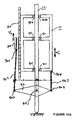
- FIG. 1E is an illustrative diagram (not to scale) of a WEC in which the shell (float) moves generally in phase with the waves and the column is untethered and can move generally out of phase with the motion of the waves with a LEG assembly connected on the outside of the shell of the WEC with means for providing velocity multiplication, in accordance with the invention;
- FIG. 1 D 1 is a more detailed diagram (not to scale) of a velocity multiplication system embodying the invention
- FIG. 1 D 2 is a diagram (not to scale) of a velocity multiplication system with the LEG positioned on the inside wall of the WEC shell;
- FIG. 1 D 3 is another diagram (not to scale) of a velocity multiplication system with the coils of a LEG installed along the outside wall of the WEC shell and the PMA passing along the outside of the coils;
- FIGS. 1 D 4 , 1 D 5 and 1 D 6 illustrate different configurations of LEGs positioned in WECs with velocity multiplication in accordance with the invention
- FIG. 1 D 7 is a diagram of (not to scale) of a velocity multiplication system in which the levering apparatus is positioned above the shell;
- FIG. 1 D 8 is a simplified diagram illustrating the principles of velocity multiplication of the invention.
- FIG. 2 is a cross-section diagram illustrating that the central column of the WEC may be multi-sided (e.g., a square column), with the inner wall of the shell having a face parallel to each side of the central column and with LEG assemblies located along the outer walls of the shell;
- multi-sided e.g., a square column
- FIGS. 3A , 3 B, 3 C and 3 D depict, illustratively, different configurations of magnetic arrays and induction coil assemblies suitable for use in practicing the invention
- FIG. 4A is illustrative of a LEG with a “surface” permanent magnet assembly configuration using electrically conductive wire, coils, bars, or foil for practicing the invention
- FIG. 4B is illustrative of a LEG with a “buried” permanent magnet assembly configuration using electrically conductive wires, coils, bars, or foils, for practicing the invention.
- FIGS. 5 a and 5 b are waveform diagrams illustrating improved voltage and power generated with LEGs installed in WECs, in accordance with the invention.
- Wave energy converters suitable for practicing the invention may include systems of the type shown in FIGS. 1A , 1 B, and 1 C.
- FIG. 1A shows a neutrally buoyant shell 10 typically submerged below the surface of the ocean with a tethered or anchored vertical column (spar) 12 .
- FIG. 1B shows a buoyant shell typically floating at the surface of the ocean also with a tethered or anchored vertical column (spar) 12 .
- FIG. 1C illustrates a dual wave energy absorber where the shell 10 and the spar 12 move relative to each other, the shell generally in phase with the waves and the spar tending to move out of phase with the shell and/or the ocean waves.
- the WECs may include one, or more, power take off (PTO) devices which include a linear electric generator (LEG) device 20 connected between the “shell” and the “spar”.
- PTO power take off
- LEG linear electric generator
- any WEC which includes first and second structures (e.g., a shell and a column) which, in response to forces such as those produced by ocean waves, move relative to each other may be suitable for practicing the invention.
- a PTO which includes a linear electric generator (LEG) 20 , may be coupled between the first and second structures to convert their relative motion into electrical energy, directly.
- LEG linear electric generator
- the PTO may be placed in many different locations, providing a high degree of freedom in the design of the physical configuration of the system.
- a linear electric generator (LEG) is proposed as the WEC's power take-off (PTO) device for a number of reasons.
- the projected efficiency of the all-electric system is estimated to be above 90% at rated force and velocity. This efficiency is well above the less than 80% efficiency of the existing hydraulic-electric system.
- the hydraulic components are also expensive, have limited life and reliability, and present installation and maintenance challenges. The elimination of the hydraulic components is an important reason for using LEGs.
- a significant benefit of the LEG is that it enables implementation of significant improvement in efficiency and survivability features.
- One aspect of the invention is that it enables implementing an active impedance matching system (AIMS) which includes feeding back power to the buoy (WEC) during a portion of each wave cycle.
- AIMS active impedance matching system
- WEC buoy
- the life of a hydraulic motor, when operated as a pump, is shortened significantly.
- the LEG can be operated as a motor and/or as a generator, depending on the direction of current flow and applied mechanical force.
- the LEG enables active impedance matching, with a resultant increase in WEC efficiency.
- a LEG can also be configured with essentially unlimited stroke. This feature has enormous benefit in terms of WEC structural design and survivability.
- the impact forces not the wave forces, control the structural design.
- existing WECs have limited stroke, driven by the finite length of the hydraulic cylinder or other mechanical PTO devices, which requires a mechanical system with end stops and dampers to absorb the impact loads.
- the anchor, universal joint, and column must also be designed to handle these loads.
- the force on the structural components is limited to that exerted by the power take-off device (the LEG in this case).
- the power take-off device the LEG in this case
- passive damping With the addition of copper or aluminum plates at the end of normal power take-off stroke, passive damping (braking) can be implemented. This damping serves to take energy out of the buoy in storm conditions.
- the structural design of a WEC using LEG systems is greatly simplified.
- the WECs shown in FIGS. 1A , 1 B an 1 C, incorporating LEG assemblies as shown in FIGS. 1D and 1E are intended to be placed in a body of water (e. g., an ocean) and the waves cause the shell 10 to move up and down relative to the central column (piston or spar) 12 . That is, the up and down motion of ocean waves applies a force to the shell 10 , causing up and down motion of the shell relative to the column 12 which may be a stationary member of the wave energy converter system. Alternatively, the column 12 may also be a moving member, but whose movement tends to be out of phase with the motion of the shell.
- a body of water e. g., an ocean
- the waves cause the shell 10 to move up and down relative to the central column (piston or spar) 12 . That is, the up and down motion of ocean waves applies a force to the shell 10 , causing up and down motion of the shell relative to the column 12 which may be a stationary member of the wave energy
- the spar 12 is shown anchored and to be stationary with the shell 10 moving up and down.
- the shell 10 and the spar 12 may both move relative to each other, with the shell tending to move, generally, in a direction opposite to the spar.
- each LEG 20 normally includes a permanent magnet assembly (PMA), 22 , and an induction coil assembly (ICA), 24 .
- PMA permanent magnet assembly
- ICA induction coil assembly
- the PMA 22 and the ICA 24 need not be encased in a common sealed housing.
- Separately enclosed magnet and induction coil assemblies provide options not possible with known common-housing linear electric machines.
- the LEG assemblies can be placed above, below, on the inside or on the outside of a WEC shell.
- FIGS. 1D and 1E show that different LEG (e.g., 20 a , 20 b ) assemblies may be placed on the outside of the WEC shell.
- one part of the LEG e.g., one of the PMA and ICA
- the other part of the LEG e.g., the other one of the PMA and ICA
- Several link (radius) arms 92 ( i ) are rotatably coupled to column 12 via a pivot point (which functions as a fulcrum) 901 .
- Each link arm 92 i is a bar or like rigid body (or may be any quadrilateral-type plate) which functions as a lever, with the pivot point 901 being the fulcrum about which the lever 92 i rotates.
- One (input) end of each link arm 92 i is shown connected to one end ( 904 ) of the shell 10 by means of a rigid rod 927 i and its other, or output, end is shown connect via a rod 923 i to a PMA or ICA assembly.
- the shell moves, up or down, (see FIG. 1 D 1 ) the one (input) end 925 , 903 of the lever 92 moves in tandem, i.e., in phase, with the shell and at the same velocity (v 1 ).
- the other, or output, end 921 , 902 of lever 92 moves in a direction opposite to the shell (and to the input end 925 ) and the input end 925 of the lever at a velocity v 2 .
- FIG. 1 D 8 is a highly simplified cross-sectional diagram illustrating the invention.
- the lever 92 which is a rigid bar is rotatably mounted on shaft 12 via a pivot pin 901 , which, as already noted, functions as a fulcrum, about which the bar 92 can swing, up or down, or rotate.
- the input end 925 of lever 92 is connected (and linked) via a rod 927 to one end 904 of shell 10 .
- the output end, 921 , of the lever is connected (linked) to one end of a rod 923 whose other end is connected to a PMA 22 .
- An ICA 24 is attached to the outside wall of the shell 10 .
- the shell 10 moves down at a speed v 1 as a result of an ocean wave.
- the shell 10 causes the input end 925 of lever 92 to be pushed down at a speed of v 1 .
- the length “a” of arm 92 is equal to the length “b”, then the output end 921 of lever 92 will move at the same rate as the input end; but, in the opposite direction (i.e., 180 degrees out of phase).
- the output end 921 drives the rod 923 and the PMA 22 .
- the lever may be described as a rigid body having two ends, with an intermediate point between the two ends, connected to the column.
- FIG. 1 D 8 the ICA is shown connected to the shell and the output end of the lever is shown connected to the PMA. But, it should be understood that the PMA could be connected to the shell and the ICA could be driven from the output end 921 of the lever via rod 923 .
- a desirable feature of this design is that the relative stator-magnet velocity may be increased substantially for producing greater electric output. As a result, the LEG force requirement and size can be decreased (e.g., halved). A disadvantage of this approach is the limited stroke that can be achieved.
- the amplitude and frequency of the voltage obtained from a LEG is a function of the velocity with which the magnets and the coils interact (i.e., the speed at which one passes over, or by, the other).
- doubling the velocity of the coils (or magnets) passing the magnets (or coils) of the LEG results in a doubling the amplitude of the voltage produced within or across the ICA.
- the coil voltage (e) produced is equal to N d ⁇ /dt; where N is a flux coupling factor and ⁇ is the magnetic flux between the PMA and the ICA. If a given change in d ⁇ occurs in 1 ⁇ 2 the time, then the amplitude of the output voltage is doubled. Consequently, it is highly desirable to increase the velocity of the coils passing along the magnets. Especially when the voltages have to be rectified and the rectifier networks cause fixed losses.
- the shaft 12 is tethered and the shell 10 is positioned about the shaft and remains so positioned; but it can move up and down relative to the central shaft 12 by means of shaft bearings 910 , 911 which enable the shell to slide up and down.
- the LEG assembly 20 includes: (a) a PMA 22 which is located on, or along, the outside wall of the shell and which runs along the length of the shell 10 ; and (b) an ICA 24 also located on the outside of the shell, exterior to the PMA.
- a radius arm 92 is rotatably connected to column 12 at a pivot point (fulcrum) 901 , whereby the two opposite ends of radius arm 92 can swing up and down, like as see-saw.
- the input end, 925 , of radius arm 92 is linked to the shell 10 and moves up and down with the shell.
- the output end, 921 , of the radius arm 92 is coupled to the ICA (or the PMA) and causes the ICA (or the PMA) to move in a direction opposite to the direction in which the shell is moving.
- Velocity multiplication is obtained by varying the ratio of the length ( 92 a , 92 b ) of the arms extending from the pivot point to the ends of the radius arms. In FIG.
- a pressure differential between the top and bottom surfaces of the WEC 10 causes the shell 10 to move downward with velocity v 1 , as shown on FIG. 1 D 1 .
- the shell 10 travels in a path, generally parallel to the shaft 12 , with the shaft 12 passing through the bearings 910 , 911 .
- the shell 10 is connected to the radius arm 92 by means of link arm 927 .
- When the shell 10 moves down it causes the input end point 903 to be pushed down and output points 921 and 902 to be driven upward. Assume that the length of the link arm from input point 903 to the central pivot point 901 is “a” and that the length of the link arm from central pivot point 901 to output point 902 is “b”.
- the lever arm 92 By changing the dimensions of “a” and/or “b”, the lever arm 92 , rotatably connected to the shaft at pivot point 901 , can be used to produce different multiplication ratios. That is, the portion 92 a of radius arm 92 extends for a distance “a” between pivot point 901 and the input end 925 of the portion 92 b of arm 92 and extends a distance “b” between pivot point 901 and the output end 921 .
- the central portion of arm (or plate) 92 of FIG. 1 D 1 may be slotted to allow the lever arm or plate to be moved laterally in order to change the ratio of the length “a” to the length “b”.
- a twin plate or bar may be placed on the opposite side of the column with the two plates being joined to provide greater strength and balance.
- the arm 92 may be moved laterally along the slot and secured such that the distances “a” and “b” may be varied.
- the velocity v 2 is equal to velocity v 1 (but in the opposite direction); when “b” is greater than “a”, the velocity v 2 is greater than v 1 .
- v 2 is twice the value of v 1 .
- the relationship of v 2 to v 1 may be expressed as follows: v 2 is approximately equal to (b/a) times v 1 .
- the significance of the velocities v 1 and v 2 is that they determine the rate at which the PMA 22 and the ICA of LEG 20 pass by each other and the quality of the output voltages generated across the ICA.
- FIG. 1 D 1 The PMA is shown attached along the length of the WEC shell 10 .
- the ICA 24 is magnetically coupled (tightly) to the PMA 22 and is physically constrained to travel along the PMA.
- the ICA is driven by rod 923 which is in turn driven by the output of lever 92 .
- ICA 24 moves upward when the shell 10 moves downward, and moves down when the shell 10 moves upwards.
- By adjusting the ratio of 92 a to 92 b different relative velocities can be obtained between the PMA 22 (functioning as the rotor) and the ICA 24 (functioning as the stator) of the LEG.
- FIG. 1 D 2 illustrates that the LEG assembly may be located on the inside wall of the shell 10 .
- the operation of this configuration is otherwise similar to that of FIG. 1 D 1 .
- FIG. 1 D 3 illustrates that the induction coil assembly 24 may be laid out along the length of the shell and a permanent magnet assembly 22 can be coupled to one end of a rod 923 so as to move back and forth across and along the coil assembly.
- FIG. 1 D 4 illustrates that a section 150 u is formed at or above the top of the shell 10 and a section 150 d is formed at or below the bottom of the shell 10 .
- Sections 150 u and 150 d may be part of the LEG assembly and provide additional travel for the coil or magnetic assembly. Alternatively, sections 150 u and 150 d may include means for braking or damping the travel of the magnetic assembly and preventing it from going beyond the top or bottom of the shell 10 .
- Sections 150 u and 150 d may include, for example, shorted coils or a copper bar or any like apparatus which will provide a strong counter force to the movement of the magnetic assembly.
- FIG. 1 D 5 illustrates that the LEG may be formed in a groove in the external wall of the shell.
- FIG. 1 D 6 illustrates that the LEG assembly could also be located along the column within the shell.
- FIG. 1 D 7 illustrates that the lever-like apparatus 942 may be located above the shell with the rigid lever 942 rotatably mounted on the column 12 via a pivot pin 980 which functions as the fulcrum of the lever 942 .
- the shell is connected to the lever via a rod 943 extending from the end of arm 942 a to connecting pin 941 located on shell 10 a distance “a” from the central column.
- the other end of arm 942 b is connected via a rod 945 to a PMA 22 and driven over a coil assembly 24 .
- the ratio of the length of arms 942 a to arm 942 b may be selected to determine the multiple of v 2 as a function of v 1 .
- the operation of the structure is otherwise similar to that already described.
- FIG. 2 shows a cross section of four LEG assemblies mounted externally to the shell 10 and which may be driven, as discussed above.
- the inner column 12 may be a square column and the inner wall(s) 110 of the shell 10 may also form a square column surrounding the column 12 for preventing rotation of the shell relative to the column.
- Each LEG assembly includes a LEG support 123 , an ICA 24 mounted on support 123 , an air gap 125 , a PMA 22 , a magnetic support plate 122 and a LEG support plate 127 .
- the PMA 22 (or ICA 24 ) and its support may be connected (linked) to a connecting arm 923 to cause the assembly to move in a direction which is opposite to the motion of the shell as discussed above.
- the location and mounting of the ICA 24 and the PMA 22 may be interchanged, as already discussed.
- FIGS. 3A , 3 B, 3 C, and 3 D are illustrative diagrams showing four possible permanent magnet and induction coil geometries.
- the magnet assembly 22 a is relatively short and designed to move relative to the induction coil assembly 24 a which is designed to be relatively long (and to be stationary or move out of phase relative to the magnetic assembly).
- the induction coil assembly 24 b is designed to be short and to be moving relative to the magnetic assembly 22 b which is designed to be long (and to be stationary or move out of phase relative to the coil assembly).
- FIG. 3A the magnet assembly 22 a is relatively short and designed to move relative to the induction coil assembly 24 a which is designed to be relatively long (and to be stationary or move out of phase relative to the magnetic assembly).
- the induction coil assembly 24 b is designed to be short and to be moving relative to the magnetic assembly 22 b which is designed to be long (and to be stationary or move out of phase relative to the coil assembly).
- the magnetic assembly 22 c is designed to be long and to be moving relative to the corresponding induction coil assembly 24 c which is designed to be short (and stationary or move out of phase relative to the magnetic assembly).
- the induction coil assembly 24 d is designed to be long and to be moving relative to the corresponding permanent magnet assembly 22 d which is designed to be short (and stationary or move out of phase relative to the coil assembly). This shows four of the many possible variations in the geometries of the coil and magnet assemblies.
- magnetic and coil assemblies may both be capable of moving at the same time (preferably at different speeds and/or in opposite directions).
- the magnets may be mounted on the inner central column (spar or shaft) and the coils may be mounted on the outer member (on the inside or the outside of the shell).
- the coils may be mounted on the inner central column (spar or piston) and the magnets may be mounted on the outer member (shell or vessel).
- FIGS. 4A and 4B are cross-sectional diagrams showing the formation of two different permanent magnet assembly and coil assembly configurations.
- FIG. 4A shows a structure which may be termed a “surface” permanent magnet configuration.
- the permanent magnets 22 s are mounted on a ferromagnetic plate 122 s which is mounted on a magnetic support structure 127 s .
- the magnetic assembly may be enclosed in a non-ferromagnetic enclosure 411 .
- the magnets (mia, mib) of the magnetic assembly are affixed to the surface of the “magnetic” plate with the magnets magnetized in a direction perpendicular to the direction of relative motion between the induction coils and the magnets (mia, mib).
- Each magnet (mia—north-south pole) has a polarity opposite to that of its neighboring magnet (mib—south-north pole).
- the induction coil assembly 24 s includes a slotted armature of ferromagnetic material which functions as a yoke mounted on a coil support structure 123 s .
- the induction coil assembly is enclosed in a non-ferromagnetic enclosure 413 . As shown in FIG.
- a magnetic “circuit” is comprised of a north polarized magnet, an air gap between the north polarized magnet and the induction coil assemblies, the coils and yoke assembly, the air gap between a south polarized magnet and coil assemblies, the south polarized magnet, and the ferro-magnetic magnet backing plate. Mechanical force and motion are converted to electrical current and voltage by means of this electromagnetic conversion.
- the slots are perpendicular to the direction of relative motion between the magnet and coil assemblies.
- Each coil is formed of electrically conductive material (e.g., copper wire) that enters a slot on one side of the yoke, exits the slot on the other side, travels towards another slot located a distance of one magnetic pole pitch in the longitudinal direction and exits the same slot on the other side of the yoke.
- the number of slots and coils may be any multiple of two per magnet assembly pole pitch.
- a three-phase implementation would have three coils placed in six slots covering a longitudinal distance equal to that of the magnet pole pitch. This pattern of coils can be repeated over the length of the coil assembly and the coils can be connected in series, electrically, to increase the voltage output.
- the motion of the coils relative to the magnets causes a voltage to be induced in the coils that is proportional to the magnitude and rate of change of magnetic flux. Electric current flows through the coils when an external load is connected across the terminals of the coils.
- FIG. 4B shows a magnet support plate 127 x on which is mounted a non-ferromagnetic yoke 122 x on which is mounted a ferromagnetic plate which includes permanent magnets contained within the ferromagnetic plate.
- FIG. 4B shows two north poles were placed next to (and opposite) each other and two south poles next to each other.
- This structure is generally referred to as a “buried” permanent magnet configuration.
- Each one of the magnetic and coil assemblies are separately enclosed in non-ferromagnetic enclosures as shown in FIG. 4A .
- the “surface magnet” configuration of FIG. 4A as well as the “buried magnet” configuration of FIG. 4B are viable options for implementing the invention.
- FIG. 5 a shows the LEG output voltage as a function of the WEC shell-to-column differential speed (i.e., the speed of the shell relative to the column).
- LEG output voltage amplitude is proportional to speed.
- LEG output voltage is also proportional to magnetic flux and coil configuration.
- LEG output voltage frequency is shown also to be proportional to speed. This may be explained as follows. Each time a coil passes over a pole pair (north-south magnets) a voltage cycle is produced. If the coil passes over the pole pair in less time (due to increased velocity), the frequency of the output voltage is increased.
- FIG. 5 b shows LEG output power as a function of WEC shell to column differential speed.
- LEG power is maximum when the shell to column speed is greatest.
- the average power of the WEC is approximately one half the peak power.
- lever arm and LEG can be contained completely within the inner portion of the shell and the inner portion of the shell can be sealed.
- Elements 910 , 911 would be seals which would keep the internal compartment of the shell sealed. In this manner the LEG can be in an air tight compartment.
- a push rod from outside the shell would enter the inner portion of the shell through the seal to activate the lever arm and drive the PMA and/or the ICA.
Landscapes
- Engineering & Computer Science (AREA)
- Power Engineering (AREA)
- Mechanical Engineering (AREA)
- Chemical & Material Sciences (AREA)
- Combustion & Propulsion (AREA)
- General Engineering & Computer Science (AREA)
- Transportation (AREA)
- Other Liquid Machine Or Engine Such As Wave Power Use (AREA)
- Linear Motors (AREA)
- Connection Of Motors, Electrical Generators, Mechanical Devices, And The Like (AREA)
- Braking Arrangements (AREA)
- Reciprocating, Oscillating Or Vibrating Motors (AREA)
- Revetment (AREA)
- Control Of Eletrric Generators (AREA)
- Ac-Ac Conversion (AREA)
- Electric Clocks (AREA)
- Electromechanical Clocks (AREA)
Priority Applications (1)
| Application Number | Priority Date | Filing Date | Title |
|---|---|---|---|
| US11/080,718 US7310944B2 (en) | 2004-03-16 | 2005-03-15 | Wave energy converters (WECs) with velocity multiplication |
Applications Claiming Priority (2)
| Application Number | Priority Date | Filing Date | Title |
|---|---|---|---|
| US55366604P | 2004-03-16 | 2004-03-16 | |
| US11/080,718 US7310944B2 (en) | 2004-03-16 | 2005-03-15 | Wave energy converters (WECs) with velocity multiplication |
Publications (2)
| Publication Number | Publication Date |
|---|---|
| US20050235641A1 US20050235641A1 (en) | 2005-10-27 |
| US7310944B2 true US7310944B2 (en) | 2007-12-25 |
Family
ID=34994240
Family Applications (3)
| Application Number | Title | Priority Date | Filing Date |
|---|---|---|---|
| US11/080,718 Expired - Fee Related US7310944B2 (en) | 2004-03-16 | 2005-03-15 | Wave energy converters (WECs) with velocity multiplication |
| US11/080,319 Active - Reinstated US7141888B2 (en) | 2004-03-16 | 2005-03-15 | Antirotational structures for wave energy converters |
| US11/080,581 Expired - Fee Related US7168532B2 (en) | 2004-03-16 | 2005-03-15 | Wave energy converter (WEC) with magnetic braking |
Family Applications After (2)
| Application Number | Title | Priority Date | Filing Date |
|---|---|---|---|
| US11/080,319 Active - Reinstated US7141888B2 (en) | 2004-03-16 | 2005-03-15 | Antirotational structures for wave energy converters |
| US11/080,581 Expired - Fee Related US7168532B2 (en) | 2004-03-16 | 2005-03-15 | Wave energy converter (WEC) with magnetic braking |
Country Status (9)
| Country | Link |
|---|---|
| US (3) | US7310944B2 (fr) |
| EP (4) | EP1738071B1 (fr) |
| JP (4) | JP4870069B2 (fr) |
| AU (4) | AU2005223056B2 (fr) |
| CA (4) | CA2537111C (fr) |
| ES (4) | ES2904287T3 (fr) |
| NO (4) | NO20061973L (fr) |
| PT (2) | PT1733141E (fr) |
| WO (4) | WO2005089379A2 (fr) |
Cited By (18)
| Publication number | Priority date | Publication date | Assignee | Title |
|---|---|---|---|---|
| US20070188046A1 (en) * | 2004-06-06 | 2007-08-16 | Commissariat A L'energie Atomique | Energy recovery device |
| US20070266704A1 (en) * | 2006-05-01 | 2007-11-22 | Diana Bull | Wave energy converter (WEC) with heave plates |
| US20100041289A1 (en) * | 2008-08-15 | 2010-02-18 | Plasti-Fab Inc. | Wave energy buoy |
| US20100230965A1 (en) * | 2009-03-09 | 2010-09-16 | Natural Power Concepts, Inc. | System and method for generating electricity using grid of wind and water energy capture devices |
| US20110036085A1 (en) * | 2007-12-19 | 2011-02-17 | Hans Oigarden | Apparatus for wave power generation |
| US20110163547A1 (en) * | 2010-09-27 | 2011-07-07 | Dov Frishberg | Apparatus for converting the energy of waves on a body of water |
| WO2012024000A1 (fr) * | 2010-02-01 | 2012-02-23 | Oscilla Power Inc. | Machine permettant de collecter l'énergie des vagues dotée d'une performance améliorée |
| US20120139261A1 (en) * | 2009-05-13 | 2012-06-07 | William Dick | Wave energy conversion system |
| US8629572B1 (en) | 2012-10-29 | 2014-01-14 | Reed E. Phillips | Linear faraday induction generator for the generation of electrical power from ocean wave kinetic energy and arrangements thereof |
| US20160186715A1 (en) * | 2014-01-20 | 2016-06-30 | Mitchell Fait | Buoy for obtaining energy from a wave in a body of water |
| US9435316B2 (en) * | 2014-10-16 | 2016-09-06 | Industrial Technology Research Institute | Wave power generation system and motion control module thereof |
| US9624900B2 (en) | 2012-10-29 | 2017-04-18 | Energystics, Ltd. | Linear faraday induction generator for the generation of electrical power from ocean wave kinetic energy and arrangements thereof |
| WO2017205970A1 (fr) * | 2016-05-30 | 2017-12-07 | Singh Ishwar Ram | Générateur à induction linéaire utilisant une répulsion magnétique |
| US9853529B2 (en) | 2014-04-29 | 2017-12-26 | Ishwar Ram Singh | Linear induction generator using magnetic repulsion |
| US10011910B2 (en) | 2012-10-29 | 2018-07-03 | Energystics, Ltd. | Linear faraday induction generator for the generation of electrical power from ocean wave kinetic energy and arrangements thereof |
| US10047717B1 (en) | 2018-02-05 | 2018-08-14 | Energystics, Ltd. | Linear faraday induction generator for the generation of electrical power from ocean wave kinetic energy and arrangements thereof |
| US20190145373A1 (en) * | 2016-04-24 | 2019-05-16 | The Regents Of The University Of California | Submerged wave energy converter for shallow and deep water operations |
| US11002243B2 (en) | 2017-04-24 | 2021-05-11 | The Regents Of The University Of California | Submerged wave energy converter for deep water operations |
Families Citing this family (66)
| Publication number | Priority date | Publication date | Assignee | Title |
|---|---|---|---|---|
| GB0316869D0 (en) * | 2003-07-18 | 2003-08-20 | Kelly H P G | Method of operation for a self-protecting wave energy conversion plant |
| US7362003B2 (en) * | 2004-03-16 | 2008-04-22 | Ocean Power Technologies, Inc. | Coil switching circuit for linear electric generator |
| US7352073B2 (en) * | 2004-06-28 | 2008-04-01 | Ames P Foerd | Ocean wave energy converter having an improved generator and ballast control |
| JP2006187079A (ja) * | 2004-12-27 | 2006-07-13 | Hitachi Ltd | 円筒型リニアモータ,電磁サスペンション及びそれを用いた車両 |
| US7323790B2 (en) * | 2005-03-15 | 2008-01-29 | Ocean Power Technologies, Inc. | Wave energy converters (WECs) with linear electric generators (LEGs) |
| US7339285B2 (en) * | 2006-01-12 | 2008-03-04 | Negron Crespo Jorge | Hydroelectric wave-energy conversion system |
| US7345372B2 (en) * | 2006-03-08 | 2008-03-18 | Perpetuum Ltd. | Electromechanical generator for, and method of, converting mechanical vibrational energy into electrical energy |
| US7420287B2 (en) * | 2006-03-28 | 2008-09-02 | Aleksandr Smushkovich | Intermittent force powered electromagnetic converters especially for sea waves |
| WO2007121382A2 (fr) * | 2006-04-14 | 2007-10-25 | Ciiis, Llc | Générateur de puissance possédant une pluralite d'unités placées selon une disposition déterminée |
| US7557456B2 (en) * | 2006-05-05 | 2009-07-07 | Sri International | Wave powered generation using electroactive polymers |
| US7538445B2 (en) * | 2006-05-05 | 2009-05-26 | Sri International | Wave powered generation |
| EP2041449B1 (fr) * | 2006-07-05 | 2011-01-05 | Ab Skf | Ressort, ensemble ressort et amortisseur, ainsi que véhicule |
| US7476986B1 (en) * | 2006-08-07 | 2009-01-13 | Del Principe David M | Wave-action energy producing apparatus |
| DE102007015168A1 (de) * | 2007-03-27 | 2008-10-02 | Trithor Gmbh | Linearmaschine mit einem Primärteil und einem Sekundärteil |
| GB2439411B (en) | 2007-04-27 | 2008-07-23 | Perpetuum Ltd | An electromechanical generator for converting mechanical vibrational energy into electrical energy |
| EP2206013A4 (fr) * | 2007-05-31 | 2011-07-20 | Artificial Muscle Inc | Systèmes optiques employant des matériaux éléctroactifs compatibles |
| JP5602626B2 (ja) | 2007-06-29 | 2014-10-08 | アーティフィシャル マッスル,インク. | 感覚性フィードバック用途のための電気活性ポリマートランスデューサー |
| US7554215B1 (en) * | 2007-07-03 | 2009-06-30 | Paul Caragine | Generator and method for generating electricity from subsurface currents |
| DE102007041128B4 (de) * | 2007-08-30 | 2011-12-29 | Schmidtsdorff Elektromotoren Reparaturwerk Und -Handel | Schwinggenerator |
| US20090079199A1 (en) * | 2007-09-25 | 2009-03-26 | Tubel Paulo S | Electric generator operated by reciprocating wellbore pump and monitoring system used therewith |
| JP4649668B2 (ja) * | 2007-11-02 | 2011-03-16 | スミダコーポレーション株式会社 | 振動型電磁発電機 |
| ES2301443B1 (es) * | 2007-11-15 | 2009-08-25 | Acciona Energia, S.A. | Sistema de medicion de recursos eolicos en el mar, productor de energia y metodo de instalacion. |
| DE102008021576A1 (de) * | 2008-04-30 | 2009-11-05 | Robert Bosch Gmbh | Hydraulischer Wandler |
| EP2318697B1 (fr) * | 2008-08-28 | 2019-01-23 | Seabased AB | Centrale houlomotrice, et utilisation de celle-ci |
| DK176883B1 (da) * | 2008-09-19 | 2010-02-22 | Wavepiston Aps | Apparat til udvinding af bølgeenergi |
| KR101082076B1 (ko) * | 2008-10-08 | 2011-11-10 | 신익수 | 파력 발전 모듈, 그 파력 발전 모듈을 포함하는 파력 발전 유닛 및 그 파력 발전 유닛을 포함하는 파력 발전 장치 |
| GB0821835D0 (en) | 2008-11-28 | 2009-01-07 | Trident Energy Ltd | Low cost linear generator wave energy converters |
| US7816797B2 (en) * | 2009-01-07 | 2010-10-19 | Oscilla Power Inc. | Method and device for harvesting energy from ocean waves |
| EP2414668B1 (fr) * | 2009-03-30 | 2016-10-12 | Ocean Power Technologies, Inc. | Convertisseur d'énergie houlomotrice (wec) à dispositif de prise de force amélioré |
| EP2239793A1 (fr) | 2009-04-11 | 2010-10-13 | Bayer MaterialScience AG | Montage de film polymère électrique commutable et son utilisation |
| US20110057448A1 (en) * | 2009-09-08 | 2011-03-10 | Joseph Page | Wave energy converters |
| PT2504567E (pt) * | 2009-11-23 | 2016-01-26 | Ocean Power Technologies Inc | Conversor de energia das ondas e sistema de tomada de potência |
| JP4680317B2 (ja) * | 2010-03-26 | 2011-05-11 | スミダコーポレーション株式会社 | 振動型電磁発電機 |
| CN102918261B (zh) * | 2010-05-28 | 2015-07-15 | 西贝斯特公司 | 用于水下使用的线性发电机及产生电能的方法 |
| KR101145084B1 (ko) | 2010-06-03 | 2012-05-11 | 이형우 | 파력발전기 |
| US20120086205A1 (en) * | 2010-10-08 | 2012-04-12 | Balakrishnan Nair | Method and device for harvesting energy from ocean waves |
| GB2486279B (en) * | 2010-12-10 | 2013-11-06 | Trident Energy Ltd | Wave energy converter |
| AU2012211089B2 (en) * | 2011-01-28 | 2015-04-09 | Oscilla Power Inc. | Energy harvesting methods and devices, and applications thereof |
| WO2012118916A2 (fr) | 2011-03-01 | 2012-09-07 | Bayer Materialscience Ag | Procédés de fabrication automatisés pour la production de dispositifs et de films polymères déformables |
| EP2689284A4 (fr) | 2011-03-22 | 2014-08-20 | Bayer Ip Gmbh | Système lenticulaire à actionneur à polymère électroactif |
| US20140084727A1 (en) * | 2011-04-07 | 2014-03-27 | Cornell University | Electrical generator apparatus, system, method, and applications |
| US9255495B2 (en) * | 2011-08-24 | 2016-02-09 | Dresser-Rand Company | Magnetically-coupled damper for turbomachinery |
| US8810056B2 (en) | 2011-09-20 | 2014-08-19 | P. Foerd Ames | Ocean wave energy converter utilizing dual rotors |
| KR101635691B1 (ko) * | 2011-11-11 | 2016-07-01 | 미쓰비시덴키 가부시키가이샤 | 통형 리니어 모터 |
| JP5853659B2 (ja) * | 2011-12-12 | 2016-02-09 | オムロン株式会社 | 発電モジュール |
| WO2013142552A1 (fr) | 2012-03-21 | 2013-09-26 | Bayer Materialscience Ag | Procédés de fabrication de rouleau à rouleau pour la production de dispositifs à polymère électroactif autoréparant |
| WO2013192143A1 (fr) | 2012-06-18 | 2013-12-27 | Bayer Intellectual Property Gmbh | Cadre d'étirement pour processus d'étirement |
| WO2014066576A1 (fr) | 2012-10-24 | 2014-05-01 | Bayer Intellectual Property Gmbh | Diode polymère |
| CA2871570C (fr) | 2012-10-26 | 2018-02-20 | William Paul Sullivan | Systeme et appareil de generation d'electricite a partir du mouvement d'un fluide |
| JP5667149B2 (ja) * | 2012-11-08 | 2015-02-12 | 網矢 貞幸 | 波発電装置 |
| US8723353B1 (en) * | 2012-11-21 | 2014-05-13 | Barrie Franklin | Wave energy converter design incorporating an induction generator |
| DE102013201716B4 (de) * | 2013-02-01 | 2015-06-03 | Sinn Power Gmbh | Lineargenerator und linearantrieb |
| CN104131951A (zh) * | 2013-05-02 | 2014-11-05 | 罗才德 | 海洋能发电船 |
| CN103485972B (zh) * | 2013-10-09 | 2016-02-03 | 东南大学 | 一种潮流波浪能发电装置 |
| FR3016755B1 (fr) * | 2014-01-17 | 2017-11-24 | Save Ingenierie | Procede de gestion d'une machine electromagnetique permettant la modification de la topologie d'un circuit d'induits de ladite machine |
| JP6344942B2 (ja) * | 2014-03-27 | 2018-06-20 | 三輪精機株式会社 | キャブチルト装置 |
| CA2964449C (fr) | 2014-10-22 | 2021-06-08 | Helder Da Costa Goncalves | Dispositif de sterilisation utilisant du peroxyde d'hydrogene et de l'ozone vaporises et combines par l'intermediaire de multiples tubes capillaires |
| US9331548B1 (en) * | 2014-12-09 | 2016-05-03 | Mohammed Al Mattar | Devices and systems for generating sustainable energy from traffic |
| US10352290B2 (en) * | 2017-02-14 | 2019-07-16 | The Texas A&M University System | Method and apparatus for wave energy conversion |
| CN106877572B (zh) * | 2017-04-13 | 2018-10-23 | 江苏科技大学 | 一种张力膜式波浪能发电装置 |
| DK179738B1 (en) | 2017-10-11 | 2019-04-30 | Ravn Niels | Wind-Driven Energy Converting Device |
| GB2572351B (en) * | 2018-03-27 | 2020-08-26 | Perpetuum Ltd | An electromechanical generator for converting mechanical vibrational energy into electrical energy |
| US10720956B2 (en) * | 2018-09-06 | 2020-07-21 | Intel Corporation | Low loss transmitter receiver switch with transformer matching network |
| JP7054714B2 (ja) * | 2020-02-17 | 2022-04-14 | 本田技研工業株式会社 | 電動サスペンション装置 |
| CN112737213B (zh) * | 2021-01-18 | 2022-04-15 | Oppo广东移动通信有限公司 | 电子设备及其供电装置 |
| IT202100016361A1 (it) * | 2021-06-22 | 2022-12-22 | Alberto Roncan | Apparecchio di generazione di corrente elettrica a rendimento migliorato |
Citations (7)
| Publication number | Priority date | Publication date | Assignee | Title |
|---|---|---|---|---|
| US1223184A (en) * | 1916-07-11 | 1917-04-17 | August Victor Larson | Wave-motor. |
| US3970415A (en) * | 1975-04-10 | 1976-07-20 | Kaj Widecrantz | One way valve pressure pump turbine generator station |
| US4363213A (en) * | 1981-03-11 | 1982-12-14 | Paleologos George E | Combined body and power generating system |
| US5710464A (en) * | 1996-01-17 | 1998-01-20 | Kao; I. Nan | Power drive system for converting natural potential energy into a driving power to drive a power generator |
| US6328539B1 (en) * | 2000-06-30 | 2001-12-11 | Sheng Hu Hung | Hydraulic device powered by wave |
| US6644027B1 (en) * | 1999-07-16 | 2003-11-11 | Hugh-Peter Granville Kelly | Apparatus for protecting a wave energy converter |
| US6857266B2 (en) * | 2000-06-16 | 2005-02-22 | Wavebob Limited | Wave energy converter |
Family Cites Families (39)
| Publication number | Priority date | Publication date | Assignee | Title |
|---|---|---|---|---|
| US852232A (en) * | 1906-11-20 | 1907-04-30 | Ernest Kohler | Wave-motor. |
| US1244309A (en) * | 1916-09-14 | 1917-10-23 | William Clay Fox | Wave-motor. |
| US2962463A (en) * | 1958-07-14 | 1960-11-29 | Union Carbide Corp | Composition comprising styrene-acrylonitrile copolymer, plasticizer and wax and method of preparing same |
| US3362336A (en) * | 1965-10-23 | 1968-01-09 | Robert S. Kafka | Wave motion operated device |
| US3546473A (en) * | 1969-02-24 | 1970-12-08 | Alan H Rich | Oceanographic generator |
| FR2050601A5 (fr) * | 1969-06-18 | 1971-04-02 | Elf Entr Rech Activit | |
| GB1316950A (en) * | 1969-06-30 | 1973-05-16 | Univ North Wales | Electric generator |
| US3996176A (en) * | 1972-03-08 | 1976-12-07 | Zareh Lorenian | Method of manufacturing shaped members of synthetic thermoplastic materials free of softeners |
| US3918261A (en) * | 1974-04-10 | 1975-11-11 | Vernon Bailey | Wave and tide motor |
| FR2319015A2 (fr) * | 1975-07-22 | 1977-02-18 | Tintillier Jean Claude | Ameliorations apportees aux moteurs thermiques |
| US4260901A (en) * | 1979-02-26 | 1981-04-07 | Woodbridge David D | Wave operated electrical generation system |
| JPS55125364A (en) * | 1979-03-22 | 1980-09-27 | Yasuhiro Manabe | Power generator with use of vertical movement of wave |
| FR2480860A1 (fr) * | 1980-04-22 | 1981-10-23 | Notari Mario | Dispositif pour recuperer l'energie des vagues et la transformer en courant electrique |
| US4378178A (en) * | 1980-09-29 | 1983-03-29 | Roach Richard T | Offshore platform system and method |
| JPS57183263A (en) * | 1981-05-07 | 1982-11-11 | Fujitsu Ltd | Linear induction motor with magnetically stopping positioning function of secondary conductor |
| DE3314335A1 (de) * | 1983-04-20 | 1984-10-31 | Tillmann 6108 Weiterstadt Freudenberg | Motorlager |
| US4539485A (en) * | 1983-10-07 | 1985-09-03 | Neuenschwander Victor L | Wave activated generator |
| JP2518206B2 (ja) * | 1986-04-21 | 1996-07-24 | 株式会社安川電機 | ブラシレス直流リニアモ−タの巻線方法 |
| PH25051A (en) * | 1988-01-26 | 1991-01-28 | Lawrence C Burton | Wave energy system |
| JPH03179170A (ja) * | 1989-12-07 | 1991-08-05 | Kumagai Gumi Co Ltd | 波浪発電装置 |
| JPH0467762A (ja) * | 1990-07-04 | 1992-03-03 | Ricoh Co Ltd | リニア直流モータ |
| JPH04155903A (ja) * | 1990-10-19 | 1992-05-28 | Shin Etsu Chem Co Ltd | 永久磁石を用いた磁気浮上用磁気回路 |
| US5167786A (en) * | 1991-01-25 | 1992-12-01 | Eberle William J | Wave-power collection apparatus |
| JP2751684B2 (ja) * | 1991-08-26 | 1998-05-18 | 神鋼電機株式会社 | リニアモ−タの固定子 |
| US5347186A (en) * | 1992-05-26 | 1994-09-13 | Mcq Associates, Inc. | Linear motion electric power generator |
| JPH06280733A (ja) * | 1993-03-24 | 1994-10-04 | Taiyo Plant Kk | 電磁誘導式波力発電装置 |
| DE4338103A1 (de) * | 1993-11-08 | 1995-05-11 | Wolf Klemm | Vorrichtung zur Gewinnung von elektrischer Energie mit Hilfe der kinetischen Energie von Wasserwellen |
| JP3278665B2 (ja) * | 1995-02-13 | 2002-04-30 | ミネベア株式会社 | リニアパルスモータ |
| SE508308C2 (sv) * | 1996-04-29 | 1998-09-21 | Ips Interproject Service Ab | Vågenergiomvandlare |
| JPH11205911A (ja) * | 1998-01-07 | 1999-07-30 | Nkk Corp | リニア式走行装置における複数走行体の搬送方法 |
| GB9916779D0 (en) * | 1999-07-16 | 1999-09-15 | Kelly H P G | Sea wave to electrical energy conversion plant |
| KR100416923B1 (ko) * | 2001-04-20 | 2004-01-31 | 주식회사 신성기연 | 파력을 이용한 자가발전 수단을 구비한 표식수단 |
| US6515375B1 (en) * | 2001-07-25 | 2003-02-04 | The United States Of America As Represented By The Secretary Of The Navy | Adaptive wave motion electrical power generator |
| NZ534543A (en) * | 2002-01-10 | 2005-06-24 | Swedish Seabased Energy Ab | A wave-power unit and the use of a wave-power unit for production of electric power, a method of generating electric power and a system of components for manufacturing a linear generator for a wave-power unit |
| US6791206B1 (en) * | 2002-06-14 | 2004-09-14 | David D. Woodbridge | Method for making a stabilized energy conversion operating platform |
| US6791205B2 (en) * | 2002-09-27 | 2004-09-14 | Aqua Magnetics, Inc. | Reciprocating generator wave power buoy |
| US7140180B2 (en) * | 2003-01-22 | 2006-11-28 | Ocean Power Technologies, Inc. | Wave energy converter (WEC) device and system |
| SE0300869L (sv) * | 2003-03-27 | 2004-03-23 | Swedish Seabased Energy Ab | Vågkraftaggregat |
| US7199481B2 (en) * | 2003-11-07 | 2007-04-03 | William Walter Hirsch | Wave energy conversion system |
-
2005
- 2005-03-15 JP JP2007504006A patent/JP4870069B2/ja not_active Expired - Fee Related
- 2005-03-15 CA CA2537111A patent/CA2537111C/fr not_active Expired - Fee Related
- 2005-03-15 AU AU2005223056A patent/AU2005223056B2/en not_active Ceased
- 2005-03-15 US US11/080,718 patent/US7310944B2/en not_active Expired - Fee Related
- 2005-03-15 PT PT57257339T patent/PT1733141E/pt unknown
- 2005-03-15 ES ES05730007T patent/ES2904287T3/es active Active
- 2005-03-15 ES ES05728147.9T patent/ES2565454T3/es active Active
- 2005-03-15 AU AU2005223057A patent/AU2005223057B2/en not_active Ceased
- 2005-03-15 WO PCT/US2005/008753 patent/WO2005089379A2/fr active Application Filing
- 2005-03-15 ES ES05725734.7T patent/ES2553727T3/es active Active
- 2005-03-15 ES ES05725733.9T patent/ES2558882T3/es active Active
- 2005-03-15 AU AU2005222962A patent/AU2005222962B2/en not_active Ceased
- 2005-03-15 US US11/080,319 patent/US7141888B2/en active Active - Reinstated
- 2005-03-15 EP EP05725734.7A patent/EP1738071B1/fr not_active Not-in-force
- 2005-03-15 JP JP2007504015A patent/JP4860601B2/ja not_active Expired - Fee Related
- 2005-03-15 JP JP2007504063A patent/JP4758983B2/ja not_active Expired - Fee Related
- 2005-03-15 PT PT57257347T patent/PT1738071E/pt unknown
- 2005-03-15 CA CA2536603A patent/CA2536603C/fr not_active Expired - Fee Related
- 2005-03-15 US US11/080,581 patent/US7168532B2/en not_active Expired - Fee Related
- 2005-03-15 WO PCT/US2005/008752 patent/WO2005089378A2/fr active Application Filing
- 2005-03-15 WO PCT/US2005/008469 patent/WO2005089284A2/fr active Application Filing
- 2005-03-15 AU AU2005222973A patent/AU2005222973B2/en not_active Ceased
- 2005-03-15 EP EP05728147.9A patent/EP1725897B1/fr not_active Not-in-force
- 2005-03-15 WO PCT/US2005/008495 patent/WO2005089295A2/fr active Application Filing
- 2005-03-15 CA CA2536598A patent/CA2536598C/fr not_active Expired - Fee Related
- 2005-03-15 EP EP05725733.9A patent/EP1733141B1/fr not_active Not-in-force
- 2005-03-15 CA CA2537110A patent/CA2537110C/fr not_active Expired - Fee Related
- 2005-03-15 JP JP2007504062A patent/JP4994221B2/ja not_active Expired - Fee Related
- 2005-03-15 EP EP05730007.1A patent/EP1735175B1/fr active Active
-
2006
- 2006-05-03 NO NO20061973A patent/NO20061973L/no not_active Application Discontinuation
- 2006-05-03 NO NO20061961A patent/NO20061961L/no not_active Application Discontinuation
- 2006-05-03 NO NO20061969A patent/NO20061969L/no not_active Application Discontinuation
- 2006-05-03 NO NO20061971A patent/NO20061971L/no not_active Application Discontinuation
Patent Citations (7)
| Publication number | Priority date | Publication date | Assignee | Title |
|---|---|---|---|---|
| US1223184A (en) * | 1916-07-11 | 1917-04-17 | August Victor Larson | Wave-motor. |
| US3970415A (en) * | 1975-04-10 | 1976-07-20 | Kaj Widecrantz | One way valve pressure pump turbine generator station |
| US4363213A (en) * | 1981-03-11 | 1982-12-14 | Paleologos George E | Combined body and power generating system |
| US5710464A (en) * | 1996-01-17 | 1998-01-20 | Kao; I. Nan | Power drive system for converting natural potential energy into a driving power to drive a power generator |
| US6644027B1 (en) * | 1999-07-16 | 2003-11-11 | Hugh-Peter Granville Kelly | Apparatus for protecting a wave energy converter |
| US6857266B2 (en) * | 2000-06-16 | 2005-02-22 | Wavebob Limited | Wave energy converter |
| US6328539B1 (en) * | 2000-06-30 | 2001-12-11 | Sheng Hu Hung | Hydraulic device powered by wave |
Cited By (29)
| Publication number | Priority date | Publication date | Assignee | Title |
|---|---|---|---|---|
| US20070188046A1 (en) * | 2004-06-06 | 2007-08-16 | Commissariat A L'energie Atomique | Energy recovery device |
| US20070266704A1 (en) * | 2006-05-01 | 2007-11-22 | Diana Bull | Wave energy converter (WEC) with heave plates |
| US7877994B2 (en) * | 2006-05-01 | 2011-02-01 | Ocean Power Technologies, Inc. | Wave energy converter (WEC) with heave plates |
| US20110036085A1 (en) * | 2007-12-19 | 2011-02-17 | Hans Oigarden | Apparatus for wave power generation |
| US20100041289A1 (en) * | 2008-08-15 | 2010-02-18 | Plasti-Fab Inc. | Wave energy buoy |
| US7785163B2 (en) * | 2008-08-15 | 2010-08-31 | Plasti-Fab Inc. | Wave energy buoy |
| US8803346B2 (en) | 2009-03-09 | 2014-08-12 | Natural Power Concepts, Inc. | System and method for generating electricity using grid of wind and water energy capture devices |
| US20100230965A1 (en) * | 2009-03-09 | 2010-09-16 | Natural Power Concepts, Inc. | System and method for generating electricity using grid of wind and water energy capture devices |
| US20120139261A1 (en) * | 2009-05-13 | 2012-06-07 | William Dick | Wave energy conversion system |
| WO2012024000A1 (fr) * | 2010-02-01 | 2012-02-23 | Oscilla Power Inc. | Machine permettant de collecter l'énergie des vagues dotée d'une performance améliorée |
| US20110163547A1 (en) * | 2010-09-27 | 2011-07-07 | Dov Frishberg | Apparatus for converting the energy of waves on a body of water |
| US7994651B2 (en) * | 2010-09-27 | 2011-08-09 | Dov Frishberg | Apparatus for converting the energy of waves on a body of water |
| US8946919B2 (en) | 2012-10-29 | 2015-02-03 | Reed E. Phillips | Linear faraday induction generator for the generation of electrical power from ocean wave kinetic energy and arrangements thereof |
| US9644601B2 (en) | 2012-10-29 | 2017-05-09 | Energystics, Ltd. | Linear faraday induction generator for the generation of electrical power from ocean wave kinetic energy and arrangements thereof |
| US8629572B1 (en) | 2012-10-29 | 2014-01-14 | Reed E. Phillips | Linear faraday induction generator for the generation of electrical power from ocean wave kinetic energy and arrangements thereof |
| US8952560B2 (en) | 2012-10-29 | 2015-02-10 | Reed E. Phillips | Linear faraday induction generator for the generation of electrical power from ocean wave kinetic energy and arrangements thereof |
| US8963358B2 (en) | 2012-10-29 | 2015-02-24 | Reed E. Phillips | Linear faraday induction generator for the generation of electrical power from ocean wave kinetic energy and arrangements thereof |
| US8946920B2 (en) | 2012-10-29 | 2015-02-03 | Reed E. Phillips | Linear faraday induction generator for the generation of electrical power from ocean wave kinetic energy and arrangements thereof |
| US10011910B2 (en) | 2012-10-29 | 2018-07-03 | Energystics, Ltd. | Linear faraday induction generator for the generation of electrical power from ocean wave kinetic energy and arrangements thereof |
| US9476400B2 (en) | 2012-10-29 | 2016-10-25 | Energystics, Ltd. | Linear faraday induction generator including a symmetrical spring suspension assembly for the generation of electrical power from ocean wave kinetic energy and arrangements thereof |
| US9624900B2 (en) | 2012-10-29 | 2017-04-18 | Energystics, Ltd. | Linear faraday induction generator for the generation of electrical power from ocean wave kinetic energy and arrangements thereof |
| US20160186715A1 (en) * | 2014-01-20 | 2016-06-30 | Mitchell Fait | Buoy for obtaining energy from a wave in a body of water |
| US9853529B2 (en) | 2014-04-29 | 2017-12-26 | Ishwar Ram Singh | Linear induction generator using magnetic repulsion |
| US9435316B2 (en) * | 2014-10-16 | 2016-09-06 | Industrial Technology Research Institute | Wave power generation system and motion control module thereof |
| US20190145373A1 (en) * | 2016-04-24 | 2019-05-16 | The Regents Of The University Of California | Submerged wave energy converter for shallow and deep water operations |
| US10767618B2 (en) * | 2016-04-24 | 2020-09-08 | The Regents Of The University Of California | Submerged wave energy converter for shallow and deep water operations |
| WO2017205970A1 (fr) * | 2016-05-30 | 2017-12-07 | Singh Ishwar Ram | Générateur à induction linéaire utilisant une répulsion magnétique |
| US11002243B2 (en) | 2017-04-24 | 2021-05-11 | The Regents Of The University Of California | Submerged wave energy converter for deep water operations |
| US10047717B1 (en) | 2018-02-05 | 2018-08-14 | Energystics, Ltd. | Linear faraday induction generator for the generation of electrical power from ocean wave kinetic energy and arrangements thereof |
Also Published As
Similar Documents
| Publication | Publication Date | Title |
|---|---|---|
| US7310944B2 (en) | Wave energy converters (WECs) with velocity multiplication | |
| US7323790B2 (en) | Wave energy converters (WECs) with linear electric generators (LEGs) | |
| KR100988667B1 (ko) | 발전 효율과 회전력 향상이 이루어진 발전장치 | |
| US20120139261A1 (en) | Wave energy conversion system | |
| CN101595628B (zh) | 开关磁阻线性电动机/发电机 | |
| Li et al. | Design and analysis of a new parallel-hybrid-excited linear vernier machine for oceanic wave power generation | |
| CN101355285A (zh) | 多层组合式直线磁阻发电机及波浪发电装置 | |
| Bizzozero et al. | Dynamic model, parameter extraction, and analysis of two topologies of a tubular linear generator for seawave energy production | |
| CN111162651A (zh) | 一种双边直线开关磁阻发电机 | |
| Kim et al. | Design and Analysis of AFPM Coreless Motor for Electric Scooter | |
| IE85792B1 (en) | A wave energy conversion system |
Legal Events
| Date | Code | Title | Description |
|---|---|---|---|
| AS | Assignment |
Owner name: OCEAN POWER TECHNOLOGIES, NEW JERSEY Free format text: ASSIGNMENT OF ASSIGNORS INTEREST;ASSIGNORS:SABOL, THOMAS;STEWART, DAVID B.;REEL/FRAME:017647/0735 Effective date: 20050629 |
|
| STCF | Information on status: patent grant |
Free format text: PATENTED CASE |
|
| FPAY | Fee payment |
Year of fee payment: 4 |
|
| FPAY | Fee payment |
Year of fee payment: 8 |
|
| SULP | Surcharge for late payment |
Year of fee payment: 7 |
|
| FEPP | Fee payment procedure |
Free format text: MAINTENANCE FEE REMINDER MAILED (ORIGINAL EVENT CODE: REM.); ENTITY STATUS OF PATENT OWNER: SMALL ENTITY |
|
| LAPS | Lapse for failure to pay maintenance fees |
Free format text: PATENT EXPIRED FOR FAILURE TO PAY MAINTENANCE FEES (ORIGINAL EVENT CODE: EXP.); ENTITY STATUS OF PATENT OWNER: SMALL ENTITY |
|
| STCH | Information on status: patent discontinuation |
Free format text: PATENT EXPIRED DUE TO NONPAYMENT OF MAINTENANCE FEES UNDER 37 CFR 1.362 |
|
| FP | Lapsed due to failure to pay maintenance fee |
Effective date: 20191225 |