US7306266B2 - Appliance latch having a rotating latch hook mounted on a linear slide - Google Patents
Appliance latch having a rotating latch hook mounted on a linear slide Download PDFInfo
- Publication number
- US7306266B2 US7306266B2 US11/071,910 US7191005A US7306266B2 US 7306266 B2 US7306266 B2 US 7306266B2 US 7191005 A US7191005 A US 7191005A US 7306266 B2 US7306266 B2 US 7306266B2
- Authority
- US
- United States
- Prior art keywords
- latch
- strike
- carriage
- appliance
- spring
- Prior art date
- Legal status (The legal status is an assumption and is not a legal conclusion. Google has not performed a legal analysis and makes no representation as to the accuracy of the status listed.)
- Expired - Lifetime, expires
Links
Images


Classifications
-
- E—FIXED CONSTRUCTIONS
- E05—LOCKS; KEYS; WINDOW OR DOOR FITTINGS; SAFES
- E05C—BOLTS OR FASTENING DEVICES FOR WINGS, SPECIALLY FOR DOORS OR WINDOWS
- E05C3/00—Fastening devices with bolts moving pivotally or rotatively
- E05C3/12—Fastening devices with bolts moving pivotally or rotatively with latching action
- E05C3/16—Fastening devices with bolts moving pivotally or rotatively with latching action with operating handle or equivalent member moving otherwise than rigidly with the latch
- E05C3/22—Fastening devices with bolts moving pivotally or rotatively with latching action with operating handle or equivalent member moving otherwise than rigidly with the latch the bolt being spring controlled
- E05C3/24—Fastening devices with bolts moving pivotally or rotatively with latching action with operating handle or equivalent member moving otherwise than rigidly with the latch the bolt being spring controlled in the form of a bifurcated member
-
- A—HUMAN NECESSITIES
- A47—FURNITURE; DOMESTIC ARTICLES OR APPLIANCES; COFFEE MILLS; SPICE MILLS; SUCTION CLEANERS IN GENERAL
- A47L—DOMESTIC WASHING OR CLEANING; SUCTION CLEANERS IN GENERAL
- A47L15/00—Washing or rinsing machines for crockery or tableware
- A47L15/42—Details
- A47L15/4251—Details of the casing
- A47L15/4257—Details of the loading door
- A47L15/4259—Arrangements of locking or security/safety devices for doors, e.g. door latches, switch to stop operation when door is open
-
- D—TEXTILES; PAPER
- D06—TREATMENT OF TEXTILES OR THE LIKE; LAUNDERING; FLEXIBLE MATERIALS NOT OTHERWISE PROVIDED FOR
- D06F—LAUNDERING, DRYING, IRONING, PRESSING OR FOLDING TEXTILE ARTICLES
- D06F37/00—Details specific to washing machines covered by groups D06F21/00 - D06F25/00
- D06F37/42—Safety arrangements, e.g. for stopping rotation of the receptacle upon opening of the casing door
-
- D—TEXTILES; PAPER
- D06—TREATMENT OF TEXTILES OR THE LIKE; LAUNDERING; FLEXIBLE MATERIALS NOT OTHERWISE PROVIDED FOR
- D06F—LAUNDERING, DRYING, IRONING, PRESSING OR FOLDING TEXTILE ARTICLES
- D06F39/00—Details of washing machines not specific to a single type of machines covered by groups D06F9/00 - D06F27/00
- D06F39/12—Casings; Tubs
- D06F39/14—Doors or covers; Securing means therefor
-
- E—FIXED CONSTRUCTIONS
- E05—LOCKS; KEYS; WINDOW OR DOOR FITTINGS; SAFES
- E05B—LOCKS; ACCESSORIES THEREFOR; HANDCUFFS
- E05B17/00—Accessories in connection with locks
- E05B17/0025—Devices for forcing the wing firmly against its seat or to initiate the opening of the wing
-
- E—FIXED CONSTRUCTIONS
- E05—LOCKS; KEYS; WINDOW OR DOOR FITTINGS; SAFES
- E05C—BOLTS OR FASTENING DEVICES FOR WINGS, SPECIALLY FOR DOORS OR WINDOWS
- E05C5/00—Fastening devices with bolts moving otherwise than only rectilinearly and only pivotally or rotatively
-
- E—FIXED CONSTRUCTIONS
- E05—LOCKS; KEYS; WINDOW OR DOOR FITTINGS; SAFES
- E05B—LOCKS; ACCESSORIES THEREFOR; HANDCUFFS
- E05B17/00—Accessories in connection with locks
- E05B17/0025—Devices for forcing the wing firmly against its seat or to initiate the opening of the wing
- E05B17/0029—Devices for forcing the wing firmly against its seat or to initiate the opening of the wing motor-operated
-
- E—FIXED CONSTRUCTIONS
- E05—LOCKS; KEYS; WINDOW OR DOOR FITTINGS; SAFES
- E05C—BOLTS OR FASTENING DEVICES FOR WINGS, SPECIALLY FOR DOORS OR WINDOWS
- E05C19/00—Other devices specially designed for securing wings, e.g. with suction cups
- E05C19/02—Automatic catches, i.e. released by pull or pressure on the wing
- E05C19/024—Automatic catches, i.e. released by pull or pressure on the wing with a bifurcated latch
-
- Y—GENERAL TAGGING OF NEW TECHNOLOGICAL DEVELOPMENTS; GENERAL TAGGING OF CROSS-SECTIONAL TECHNOLOGIES SPANNING OVER SEVERAL SECTIONS OF THE IPC; TECHNICAL SUBJECTS COVERED BY FORMER USPC CROSS-REFERENCE ART COLLECTIONS [XRACs] AND DIGESTS
- Y10—TECHNICAL SUBJECTS COVERED BY FORMER USPC
- Y10T—TECHNICAL SUBJECTS COVERED BY FORMER US CLASSIFICATION
- Y10T292/00—Closure fasteners
- Y10T292/08—Bolts
- Y10T292/096—Sliding
- Y10T292/1037—Pivoted end
-
- Y—GENERAL TAGGING OF NEW TECHNOLOGICAL DEVELOPMENTS; GENERAL TAGGING OF CROSS-SECTIONAL TECHNOLOGIES SPANNING OVER SEVERAL SECTIONS OF THE IPC; TECHNICAL SUBJECTS COVERED BY FORMER USPC CROSS-REFERENCE ART COLLECTIONS [XRACs] AND DIGESTS
- Y10—TECHNICAL SUBJECTS COVERED BY FORMER USPC
- Y10T—TECHNICAL SUBJECTS COVERED BY FORMER US CLASSIFICATION
- Y10T292/00—Closure fasteners
- Y10T292/08—Bolts
- Y10T292/1043—Swinging
- Y10T292/1044—Multiple head
- Y10T292/1045—Operating means
- Y10T292/1047—Closure
-
- Y—GENERAL TAGGING OF NEW TECHNOLOGICAL DEVELOPMENTS; GENERAL TAGGING OF CROSS-SECTIONAL TECHNOLOGIES SPANNING OVER SEVERAL SECTIONS OF THE IPC; TECHNICAL SUBJECTS COVERED BY FORMER USPC CROSS-REFERENCE ART COLLECTIONS [XRACs] AND DIGESTS
- Y10—TECHNICAL SUBJECTS COVERED BY FORMER USPC
- Y10T—TECHNICAL SUBJECTS COVERED BY FORMER US CLASSIFICATION
- Y10T292/00—Closure fasteners
- Y10T292/08—Bolts
- Y10T292/1043—Swinging
- Y10T292/1044—Multiple head
- Y10T292/1045—Operating means
- Y10T292/1049—Rigid
Definitions
- the present invention relates to a latching mechanism for doors on household appliances and particularly to latching mechanisms that provide assistance in compressing a door gasket or the like.
- Appliances such as dishwashers and front-loading washing machines may have an access door with a gasket that must be compressed to seal water within a washing chamber. Small area, highly compliant gaskets may be sealed by pressure from the user during the closing the door. The gasket may then be held in a compressed state by a latch mechanism.
- Gaskets which require more force may be compressed by a latch mechanism having a lever operated by the user to engage a catch and draw the catch inward with a lever advantage to compress the gasket and hold the door shut.
- a closing lever may be avoided in latch mechanisms that provide an “over-center” spring mechanism.
- closing force on the door is used to energize a spring.
- the spring releases its energy in a manner to pull the door fully closed.
- An example an over-center spring mechanism is described in U.S. Pat. No. 4,497,513 to Sasaki.
- over-center spring mechanism energizes the spring as the door is opened and holds that energy until the door is closed again.
- An over-center design is still employed and therefore a slight compression of the spring is required when the door is closed to release the energy.
- a latch of this kind is disclosed in U.S. Pat. No. 2,833,578 to Burke.
- U.S. Pat. No. 6,290,270 to Spiessl shows a variation on Burke in which the latch spring is energized when the door is opened and held in the energized state by the rotation of a cam. When the door is closed, the cam is rotated by a strike to release the energized spring. This design reduces the force required to close the door by eliminating the need to compress an over-center spring mechanism during door closure.
- the cam is held on a lever, and the energized spring moves the lever and cam.
- the spring engages the lever “outboard” of the cam to produce the necessary force over the needed distance with a manageable spring size.
- the lever in this design provides for a relatively narrow latch but increases the required height of the latch because of the necessary length of the lever and the outboard position of the spring.
- the lever is subject to significant bending forces making it difficult to implement the lever using injection molded thermoplastic, a material that is otherwise desirable in this application.
- the present invention provides a latch in which a locking cam is held on a carriage that slides linearly, preferably under the force of a series of balanced springs.
- the present invention provides an appliance latch for retaining a strike and having a latch frame affixable to a portion of the appliance, for example, the door or appliance housing.
- a carriage slideably held by the latch frame moves along a line substantially parallel to an axis along which the latch receives the strike.
- At least one spring biases the carriage along this line in the direction from which the latch receives the strike.
- a rotating hook is supported by the carriage to move with the carriage and to rotate about an axis perpendicular to the line. The rotating hook rotates to capture a portion of the strike in a capture position when the strike enters the hook opening, and rotates to release the strike in a release position when the strike exits the hook opening.
- a catch holds the carriage in a first position along the line with the spring in a high state of compression when the rotating hook is in the release position and releases the carriage in a second position along the line with the spring in a lower state of compression when the rotating hook is in the capture position. In this way, energy stored in the spring when opening the latch is returned to aid in closing the latch.
- Multiple compression springs may bias the carriage in a direction along which the latch receives the strike.
- the multiple compression springs may be place symmetrically about the rotating hook, for example, at the corners of a rectangle surrounding the rotating hook.
- the carriage may slide on rails fixed with respect to the latch frame and the compression springs may symmetrically flank each rail.
- the rotating hook may include a cam surface compressed by the spring against a stop fixed with respect to the latch frame and the cam surface may have a high radius portion holding the carriage in the first position when the rotating hook is in the release position and the low radius portion releasing the carriage to a second position along the line with the spring in a lower state of compression when the rotating hook is in the capture position.
- the stop may be a rod extending between the rails along which the carriage slides.
- the appliance latch may further include a lock having a locked and unlocked state, the lock preventing the strike from exiting the latch when the lock is in the locked state.
- the lock in the locked state, may position a blocking member between the strike and structure fixed with respect to the latch frame so that a disengaging force on the strike does not place substantial force on the rotating hook or carriage.
- the lock may include a lock stop preventing the lock from moving to the locked state when the strike has not engaged the hook.
- the lock stop for example, may be attached to the carriage to interfere with a sliding lock bar of the lock when the carriage is in a first position and the lock stop may be spring loaded to allow some movement of the carriage under forces from the strike when the carriage is in the first position and the lock is in the locked state.
- a spring may be incorporated into the latch to bias the rotating hook toward the release position.
- the spring may be a leaf spring pressing against a surface of the rotating hook.
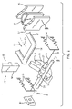
- FIG. 1 is a perspective view of the principal components of the latch of the present invention providing a linear carriage (abstracted for clarity) biased on springs and supporting a rotating hook abutting a stop to engage a strike;
- FIG. 2 is a cross-sectional view along line 2 — 2 of FIG. 1 showing the components of FIG. 1 assembled on the linear carriage in a first position with springs in a high state of compression and the rotating hook in the release position prior to receiving the strike;
- FIG. 3 is a figure similar to that of FIG. 2 showing the carriage in a second position with the springs in a lower state of compression and the rotating hook in the capture position;
- FIG. 4 is a view of the rotating hook showing its cam surfaces
- FIG. 5 is a front elevational view of the lock mechanism that may be used with the latch of the present invention showing electrical connections to a door close switch, a locking state switch and a bi-directional actuator;
- FIGS. 6 and 7 are fragmentary side views of the stop of FIG. 5 showing the spring-loaded plunger providing a lock stop preventing locking when the linear carriage is in the first position.
- an appliance latch 10 of the present invention works with a strike 12 , in this case, a U-shaped rod having a laterally extending strike bar 14 .
- the strike 12 may be attached to a first portion 15 of an appliance, for example the appliance door, to be received by the appliance latch 10 attached to a second portion 17 of the appliance, for example, the appliance housing against which the door is closed.
- the strike bar 14 of the strike 12 may engage a hook opening 16 of a rotating hook 18 .
- the rotating hook 18 rotates on axle 27 about an axis 25 generally perpendicular to axis 20 and may receive the strike along an axis 20 in a direction 22 .
- the rotating hook 18 is mounted to a linear carriage 24 of the appliance latch 10 .
- the linear carriage 24 is supported on a plurality of springs 26 to move in a line substantially along axis 20 .
- the springs 26 which may be helical compression springs, urge the linear carriage 24 along direction 22 .
- a stop 28 is positioned behind the rotating hook 18 with respect to the strike 12 and may be a laterally extending metal bar generally perpendicular to axis 20 .
- the stop 28 limits translative motion of the rotating hook 18 in direction 22 through interference between the stop 28 and cam surfaces 34 at the radial outer periphery of the rotating hook 18 .
- the stop 28 may also prevent rotation of the rotating hook 18 under certain circumstances to be described below.
- the stop 28 is held fixed by a pair of rails 30 (only one shown in FIG. 1 ) with respect to a latch frame 32 attached to the second portion 17 of the appliance.
- the rails 30 also provide a sliding support for the linear carriage 24 .
- the rotating hook 18 may be positioned approximately in the center of the linear carriage 24 and the springs 26 placed at comers of a rectangle circumscribing the rotating hook and symmetrically flanking about the axis of the rotating hook 18 and the rails 30 on which the linear carriage 24 rides to eliminate problems of binding or the like.
- the linear carriage 24 will be in a first state with springs 26 highly compressed and the linear carriage 24 moved fully forward in a direction opposite direction 22 .
- the linear carriage 24 is and held in this position with the springs 26 fully compressed by contact of a high-radius cam surface 34 a of the rotating hook 18 with the stop 28 held by the rail 30 .
- the springs 26 are sized to compress the gasket 35 into a sealing condition. Resistance of the gasket 35 to compression causes the rotating hook 18 to experience a clockwise force as the rotating hook 18 pulls against the strike 12 . Referring to FIGS. 3 and 4 , this clockwise force on the rotating hook 18 is resisted by a radially-extending cam surface 34 c positioned between the high-radius cam surface 34 a and the low-radius cam surface 34 b which blocks clockwise motion of the rotating hook 18 once the linear carriage 24 has moved along direction 22 away from its first position.
- a force may be applied to the strike 12 in a direction opposite direction 22 . Initially, this force draws the rotating hook 18 and the linear carriage 24 forward without rotation of the rotating hook 18 compressing springs 26 . Rotation of the rotating hook 18 is prevented by interference between stop 28 and radially-extending cam surface 34 c.
- a restoring clockwise torque may be exerted on the hook 18 by a leaf spring 42 to ensure that the rotating hook 18 stays a fully clockwise position with jarring or vibration.
- the leaf spring 42 has one end attached to the linear carriage 24 and the other end pressing radially inward against a spiral cam surface 44 so that the inward pressing of the leaf spring 42 provides a slight clockwise bias to the rotating hook 18 preventing it from being misaligned during closing of the appliance door per FIG. 2 .
- the end of the leaf spring 42 attached to the linear carriage 24 may have a hook end 46 allowing it to be snapped in place onto the linear carriage 24 after assembly of the rotating hook 18 to the linear carriage 24 .
- This design eliminates the need to install a torsion spring in compression around the axle 27 of the rotating hook 18 such as may prove difficult in manufacture.
- the present invention provides for lock 48 providing a bolt 50 shown in FIGS. 1 , 2 and 3 that may move between the latch frame 32 and the strike bar 14 when the appliance latch 10 is closed with the linear carriage 24 in the second position holding the door shut. Opening force (opposite direction 22 ) on the strike 12 pulls a lower lip 52 of the opening 16 of the hook 18 against the bolt 50 so that the rearward flat surface of the bolt 50 abuts a flat cam surface 54 of the lower lip 52 .
- the front surface of the bolt 50 away from the rotating hook 18 is fully supported by the latch frame 32 and ultimately the structure of the appliance housing or door on which the latch frame is mounted so that the bolt 50 also experiences primarily compressive as opposed to bending forces.
- the bolt 50 may also be molded of common thermoplastic materials.
- the bolt 50 may be attached to a slide 56 driven by a bi-directional solenoid 58 of type well-known in the art according to electrical signals provided to terminals 60 .
- the bi-directional solenoid may move the slide 56 to either of two lateral positions to push the bolt 50 leftward into position under the rotating hook 18 (per FIG. 3 ) or to retract the bolt 50 rightward (as shown in FIGS. 2 and 5 ).
- a pair of contacts 63 may communicate with the slide 56 to provide a signal through terminals 64 indicating that the bolt 50 is positioned to block the retraction of the strike 12 and a push button door closure switch 66 provides a signal that the door is closed through terminals 68 .
- a control circuit (not shown) attached to the terminals 60 , 64 and 68 may enforce a sequence of operations of the appliance latch 10 allowing the bolt 50 to be moved leftward to lock the appliance latch 10 only when the door is closed as indicated by switch 66 and to allow starting of the appliance only after confirmation of that locking has occurred per contacts 63 .
- the slide 56 may include a projection 72 extending from the slide 56 in a direction perpendicular to the slide that may engage a spring-loaded lock stop 70 to prevent locking of the appliance latch 10 when the linear carriage 24 has not fully retracted to the second position.
- a projection 72 extending from the slide 56 in a direction perpendicular to the slide that may engage a spring-loaded lock stop 70 to prevent locking of the appliance latch 10 when the linear carriage 24 has not fully retracted to the second position.
- the lock stop 70 interferes with movement of the slide 56 leftward to a locking position by interference between projection 72 and the lock stop 70 .
- the lock stop 70 also moves upward allowing passage of projection 72 and leftward movement of the slide 56 .
- the linear carriage 24 may be moved slightly by an attempted opening of the door.
- the lock stop 70 is spring loaded so as to retract slightly in this case, against the projection 72 .
- the lock stop 70 prevents the appliance latch 10 from being activated when the appliance latch 10 is not fully engaged and yet allows the linear carriage 24 to move slightly within a predefined range when it is in a locked condition.
Landscapes
- Engineering & Computer Science (AREA)
- Textile Engineering (AREA)
- Mechanical Engineering (AREA)
- Closing And Opening Devices For Wings, And Checks For Wings (AREA)
- Lock And Its Accessories (AREA)
Abstract
Description
Claims (22)
Priority Applications (3)
| Application Number | Priority Date | Filing Date | Title |
|---|---|---|---|
| US11/071,910 US7306266B2 (en) | 2004-03-05 | 2005-03-04 | Appliance latch having a rotating latch hook mounted on a linear slide |
| DE102006007418.1A DE102006007418B4 (en) | 2005-03-04 | 2006-02-17 | Appliance latch with twist lock hook attached to a linear carriage |
| CN200610059546A CN100580213C (en) | 2005-03-04 | 2006-03-03 | Instrument lock with rotary shackle mounted on linear slide |
Applications Claiming Priority (2)
| Application Number | Priority Date | Filing Date | Title |
|---|---|---|---|
| US55052604P | 2004-03-05 | 2004-03-05 | |
| US11/071,910 US7306266B2 (en) | 2004-03-05 | 2005-03-04 | Appliance latch having a rotating latch hook mounted on a linear slide |
Publications (2)
| Publication Number | Publication Date |
|---|---|
| US20050194795A1 US20050194795A1 (en) | 2005-09-08 |
| US7306266B2 true US7306266B2 (en) | 2007-12-11 |
Family
ID=36848303
Family Applications (1)
| Application Number | Title | Priority Date | Filing Date |
|---|---|---|---|
| US11/071,910 Expired - Lifetime US7306266B2 (en) | 2004-03-05 | 2005-03-04 | Appliance latch having a rotating latch hook mounted on a linear slide |
Country Status (3)
| Country | Link |
|---|---|
| US (1) | US7306266B2 (en) |
| CN (1) | CN100580213C (en) |
| DE (1) | DE102006007418B4 (en) |
Cited By (18)
| Publication number | Priority date | Publication date | Assignee | Title |
|---|---|---|---|---|
| US20050257813A1 (en) * | 2004-05-20 | 2005-11-24 | Shin Kap S | Dishwasher and door locking device for the same |
| US20050285412A1 (en) * | 2004-05-20 | 2005-12-29 | Lg Electronics Inc. | Dishwasher and door locking device for the same |
| US20070200368A1 (en) * | 2005-11-28 | 2007-08-30 | Oshkosh Truck Corporation | Compartment door latch mechanism |
| US20080169657A1 (en) * | 2005-03-05 | 2008-07-17 | Southco, Inc. | Rotary Pawl Latch And Rocker Switch |
| US20100052338A1 (en) * | 2007-05-24 | 2010-03-04 | Illinois Tool Works Inc. | Gasket-compensating latch mechanism |
| US20100077803A1 (en) * | 2008-04-30 | 2010-04-01 | Lg Electronics Inc. | Laundry machine |
| US20110285151A1 (en) * | 2010-05-19 | 2011-11-24 | Harris Corporation | Latch assembly, over-center reverse draw |
| US20120175894A1 (en) * | 2009-09-10 | 2012-07-12 | Illinois Tool Works Inc. | Appliance lock with mechanical door sensor |
| US20120292924A1 (en) * | 2009-11-26 | 2012-11-22 | Fabrizio Promutico | Door-Locking Device for Locking the Door of Household Appliance |
| WO2015167716A1 (en) | 2014-05-01 | 2015-11-05 | Illinois Tool Works Inc. | Low closure force motorized latch |
| US9370294B2 (en) | 2012-09-10 | 2016-06-21 | Illinois Tool Works Inc. | Stored energy gasket-compressing latch with reduced rotational friction |
| US20170362766A1 (en) * | 2016-06-20 | 2017-12-21 | Lg Electronics Inc. | Latch lock and home appliance including the same |
| CN108486828A (en) * | 2018-06-07 | 2018-09-04 | 温州天健电器有限公司 | A kind of door lock of washing machine |
| WO2018236850A1 (en) | 2017-06-23 | 2018-12-27 | Illinois Tool Works Inc. | APPARATUS DOOR LATCH SYSTEM WITH PRELOCKING RATCH ALIGNMENT SYSTEM AND APPARATUS WITH SAID DOOR LATCH SYSTEM |
| US20210238888A1 (en) * | 2020-01-31 | 2021-08-05 | Bitron S.P.A. | Door-lock device and household appliance equipped with such door-lock device |
| US11898369B2 (en) * | 2017-06-19 | 2024-02-13 | Illinois Tool Works Inc. | Door lock |
| US11982041B2 (en) | 2021-02-23 | 2024-05-14 | Whirlpool Corporation | Spring-loaded side swing hinge with feedback elimination |
| EP4467705A1 (en) | 2023-05-24 | 2024-11-27 | Arçelik Anonim Sirketi | A laundry washer and/or dryer comprising a door |
Families Citing this family (57)
| Publication number | Priority date | Publication date | Assignee | Title |
|---|---|---|---|---|
| US7900979B2 (en) * | 2003-06-27 | 2011-03-08 | Illinois Tool Works, Inc. | Low power consumption lock for appliance latch |
| US7306266B2 (en) | 2004-03-05 | 2007-12-11 | Illinois Tool Works, Inc. | Appliance latch having a rotating latch hook mounted on a linear slide |
| US7370901B2 (en) * | 2006-02-03 | 2008-05-13 | Toyota Motor Engineering & Manufacturing North America, Inc. | Glove box assembly |
| US7350841B2 (en) | 2006-02-03 | 2008-04-01 | Toyota Motor Engineering & Manufacturing North America, Inc. | Glove box assembly |
| DE102006037494B4 (en) * | 2006-08-10 | 2008-07-24 | Emz-Hanauer Gmbh & Co. Kgaa | Door closing device for a household electrical appliance, in particular a dishwashing machine |
| US20080314100A1 (en) * | 2006-09-25 | 2008-12-25 | Hao Min | Electric Anti-Impact Lock with Spring Accumulator |
| DE102006054414B3 (en) * | 2006-11-16 | 2008-01-31 | Miele & Cie. Kg | Door lock for a household appliance comprises a closing lever with a pivoting axle arranged in a position above the lock latch in the operating state of the appliance when the door is closed |
| DE202006018500U1 (en) * | 2006-12-05 | 2008-04-17 | Kiekert Ag | Motor vehicle door lock |
| DE102007044577B4 (en) | 2007-09-19 | 2009-11-05 | Emz-Hanauer Gmbh & Co. Kgaa | Door closing device for a household electrical appliance |
| KR100888167B1 (en) * | 2008-03-14 | 2009-03-10 | 동우정밀(주) | Door opening and closing unit |
| US8973956B2 (en) * | 2008-10-29 | 2015-03-10 | Nifco Inc. | Latch device |
| US8505987B2 (en) * | 2009-03-17 | 2013-08-13 | GM Global Technology Operations LLC | Electrically-activated hood latch and release mechanism |
| US20120102840A1 (en) * | 2009-07-07 | 2012-05-03 | 3Form, Inc. | Sliding partition fasteners |
| ITTO20090560A1 (en) | 2009-07-23 | 2011-01-24 | Illinois Tool Works | SELF-POSSIBLE DOOR LOCKING DEVICE FOR APPLIANCES, IN PARTICULAR A DISHWASHER |
| ES2386266A1 (en) * | 2009-08-25 | 2012-08-14 | BSH Electrodomésticos España S.A. | Dishwasher, in particular household dishwasher |
| KR100980441B1 (en) * | 2010-02-25 | 2010-09-07 | 두얼메카닉스 주식회사 | Door lock apparatus |
| IT1399631B1 (en) * | 2010-04-21 | 2013-04-26 | Elettrotecnica Rold Srl | "PUSH-PULL" CLOSING DEVICE |
| EP2439324B1 (en) * | 2010-10-07 | 2013-12-04 | Electrolux Home Products Corporation N.V. | Door for laundry machine |
| DE102010051518B4 (en) * | 2010-11-16 | 2014-04-24 | Emz-Hanauer Gmbh & Co. Kgaa | Door lock for a household electrical appliance |
| IT1404221B1 (en) * | 2011-01-24 | 2013-11-15 | Bitron Spa | DOOR-LOCK DEVICE FOR A DOOR OF A HOUSEHOLD APPLIANCE |
| US9243427B2 (en) | 2011-01-24 | 2016-01-26 | Carefusion 303, Inc. | Self-aligning modular latch |
| DE102011011662B4 (en) | 2011-02-18 | 2018-09-20 | Emz-Hanauer Gmbh & Co. Kgaa | Dishwasher with a door lock |
| ITTO20120087A1 (en) * | 2012-02-03 | 2013-08-04 | Elbi Int Spa | DOOR-LOCKING DEVICE FOR A APPLIANCE APPLIANCE IN PARTICULAR FOR A WASHING MACHINE, AS A DISHWASHER MACHINE. |
| DE102012203484A1 (en) * | 2012-03-06 | 2013-09-12 | BSH Bosch und Siemens Hausgeräte GmbH | household appliance |
| CN103356146B (en) * | 2012-04-09 | 2017-06-23 | 伊利诺斯工具制品有限公司 | Door lock with water-proof function and equipped with this kind of dish-washing machine of door lock |
| FR2989942B1 (en) * | 2012-04-30 | 2016-11-04 | Renault Sa | SYSTEM FOR LOCKING AN ANCHORING LEG OF A REMOVABLE MEMBER, IN PARTICULAR A TENDER FOR A VEHICLE, AND A VEHICLE THEREFOR |
| KR101575929B1 (en) * | 2013-06-05 | 2015-12-08 | 주식회사 니프코코리아 | Button Latch Device of Inner Door Having Double Door Type |
| ITTO20130691A1 (en) * | 2013-08-13 | 2015-02-14 | Elbi Int Spa | EQUIPMENT TO CHECK THE CLOSURE OF A DOOR OF A HOUSEHOLD APPLIANCE, IN PARTICULAR FOR A WASHING MACHINE, AS A DISHWASHER MACHINE. |
| WO2015189668A1 (en) * | 2014-06-13 | 2015-12-17 | Illinios Tool Works Inc. | An electromagnetic door lock |
| FR3028548A1 (en) | 2014-11-19 | 2016-05-20 | Bitron Spa | DOOR LOCKING DEVICE |
| CN104746982B (en) * | 2015-03-26 | 2016-08-31 | 芜湖美的洗涤电器制造有限公司 | Dish washing machine door latch mechanism and dish-washing machine |
| CN106048982B (en) * | 2015-04-10 | 2019-04-19 | 伊利诺斯工具制品有限公司 | Door lock |
| CN104948045B (en) * | 2015-05-27 | 2017-06-30 | 乐歌人体工学科技股份有限公司 | Self-locking mechanism |
| EP3118398B1 (en) * | 2015-07-16 | 2018-07-11 | Opacmare S.r.l. | Watertight door or window |
| CN105193294B (en) * | 2015-09-15 | 2017-07-28 | 佛山市千城产品设计有限公司 | Pressure oven |
| WO2017059911A1 (en) * | 2015-10-08 | 2017-04-13 | Arcelik Anonim Sirketi | Laundry machine having an improved door locking mechanism |
| KR102435757B1 (en) * | 2016-01-05 | 2022-08-25 | 엘지전자 주식회사 | Locker and Home Appliance having the same |
| US10329822B2 (en) * | 2016-04-04 | 2019-06-25 | Global Cooling, Inc. | Door latch with opening and closing mechanical advantage |
| US11519125B2 (en) * | 2016-07-06 | 2022-12-06 | Illinois Tool Works Inc. | Door lock |
| DE102016008317B4 (en) * | 2016-07-07 | 2018-10-31 | Emz-Hanauer Gmbh & Co. Kgaa | Door lock for a household electrical appliance |
| IT201600105630A1 (en) * | 2016-10-20 | 2018-04-20 | Bitron Spa | Improved double push-lock device. |
| CN106725207B (en) * | 2016-12-28 | 2023-04-28 | 广东格兰仕集团有限公司 | Door lock structure of dish washer |
| CN107287869A (en) * | 2017-07-14 | 2017-10-24 | 神龙电气有限公司 | Cloth drier door lock-switch |
| IT201700099948A1 (en) * | 2017-09-06 | 2019-03-06 | Elettrotecnica Rold Srl | DEVICE FOR CLOSING AND OPENING OF SHUTTERS, IN PARTICULAR OF HOUSEHOLD APPLIANCES SUCH AS WASHING MACHINES OR SIMILAR |
| US10829953B2 (en) | 2017-12-12 | 2020-11-10 | Haier Us Appliance Solutions, Inc. | Damped closure assembly for a microwave oven |
| CN109667111B (en) * | 2019-01-03 | 2022-09-23 | 无锡小天鹅电器有限公司 | Drum type washing machine's stopper and drum type washing machine |
| DE102019005564B3 (en) | 2019-05-10 | 2020-09-17 | Emz-Hanauer Gmbh & Co. Kgaa | Door lock for an electrical household appliance |
| EP3782800A1 (en) * | 2019-08-23 | 2021-02-24 | LayerWise N.V. | Three-dimensional printing system with improved build chamber |
| DE102019007428B3 (en) | 2019-10-24 | 2020-12-10 | Emz-Hanauer Gmbh & Co. Kgaa | Door lock for an electrical household appliance and a method for assembling such a device |
| DE102020124399B3 (en) | 2020-08-31 | 2021-10-21 | Emz-Hanauer Gmbh & Co. Kgaa | Electric household appliance and door lock therefor |
| PL4043635T3 (en) * | 2021-02-15 | 2024-02-19 | BSH Hausgeräte GmbH | Door lock for household apliance, and household appliance comprising such door |
| EP4338652B1 (en) * | 2021-05-13 | 2026-04-29 | Samsung Electronics Co., Ltd | Door opening and closing device for a dishwasher |
| EP4098554B1 (en) * | 2021-05-31 | 2023-10-25 | Airbus Operations GmbH | Door locking device and aircraft with door locking device |
| CN113585888B (en) * | 2021-08-27 | 2022-05-06 | 广东美的厨房电器制造有限公司 | Door locks and cooking utensils |
| CN117449708A (en) * | 2022-07-19 | 2024-01-26 | 广东美的厨房电器制造有限公司 | Locking components and cooking utensils |
| JP2025020091A (en) * | 2023-07-21 | 2025-02-12 | イリノイ トゥール ワークス インコーポレイティド | Door Lock Assembly and Electrical Equipment |
| JP2025020090A (en) * | 2023-07-21 | 2025-02-12 | イリノイ トゥール ワークス インコーポレイティド | Door Lock Assembly and Electrical Equipment |
Citations (19)
| Publication number | Priority date | Publication date | Assignee | Title |
|---|---|---|---|---|
| US775524A (en) * | 1904-05-31 | 1904-11-22 | John C Deggim | Window-sash lock. |
| US965125A (en) | 1909-08-17 | 1910-07-19 | Joseph E Terrell | Latch. |
| US1932829A (en) * | 1931-10-21 | 1933-10-31 | Stanley Works | Latch for refrigerator doors and the like |
| US2833578A (en) | 1956-11-14 | 1958-05-06 | Nat Lock Co | Refrigerator latch mechanism |
| US3968984A (en) | 1975-04-14 | 1976-07-13 | General Electric Company | Door latch |
| US3985023A (en) | 1975-11-04 | 1976-10-12 | General Electric Company | Door latch control means for a dishwasher |
| US4279321A (en) * | 1980-01-09 | 1981-07-21 | Paccar Inc | Latching system for a truck cab |
| US4497513A (en) | 1981-09-21 | 1985-02-05 | Tokyo Shibaura Denki Kabushiki Kaisha | Locking device for door of cooking apparatus |
| DE4317135C1 (en) | 1993-05-21 | 1994-09-01 | Zangenstein Elektro | Door fastening for electrical domestic appliances |
| DE4343975C2 (en) | 1993-12-22 | 1997-04-24 | Bosch Siemens Hausgeraete | Door lock for a household appliance |
| DE19540843A1 (en) | 1995-10-30 | 1997-05-07 | Zangenstein Elektro | Fastener for door of domestic electrical device, esp. dishwasher |
| DE19601228A1 (en) | 1996-01-15 | 1997-07-17 | Zangenstein Elektro | Door locking apparatus for washing machine etc. |
| US5725260A (en) * | 1994-11-08 | 1998-03-10 | Wilhelm Weidtmann Gmbh & Co. Kg | Locking arrangement for windows, doors or the like |
| DE19837248A1 (en) | 1998-07-28 | 2000-02-10 | Zangenstein Elektro | Door lock for domestic electrical apparatus, especially dish washer has closing spring tensioned in open position of door lock, this having movable gripping device joined to closing member |
| US6155616A (en) * | 1997-06-16 | 2000-12-05 | Randall C. Hansen | Locking mechanism and closure assembly including same |
| US6290270B1 (en) | 1998-07-28 | 2001-09-18 | Elektromanufactur Zangenstein Hanauer Gmbh & Co. Kgaa | Door lock for an electrical household appliance |
| US6390518B1 (en) * | 2000-08-15 | 2002-05-21 | Maytag Corporation | Latching mechanism for an appliance door |
| US20020073752A1 (en) * | 2000-12-01 | 2002-06-20 | Albert Dirnberger | Door Lock |
| EP1217117A1 (en) | 2000-12-22 | 2002-06-26 | Elektromanufaktur Zangenstein, Hanauer GmbH & Co. KGaA | Apparatus to lock and unlock a door closure for an electrical appliance |
Family Cites Families (5)
| Publication number | Priority date | Publication date | Assignee | Title |
|---|---|---|---|---|
| US1915492A (en) * | 1932-01-09 | 1933-06-27 | Eberhard Mfg Company | Hood fastener |
| US4045063A (en) * | 1975-12-18 | 1977-08-30 | Nasa | Load regulating latch |
| JP2590049B2 (en) * | 1994-10-24 | 1997-03-12 | タキゲン製造株式会社 | Latch device |
| US6966582B1 (en) * | 2001-11-02 | 2005-11-22 | France/Scott Fetzer Company | Lock rod clutch for oven latch |
| US7306266B2 (en) | 2004-03-05 | 2007-12-11 | Illinois Tool Works, Inc. | Appliance latch having a rotating latch hook mounted on a linear slide |
-
2005
- 2005-03-04 US US11/071,910 patent/US7306266B2/en not_active Expired - Lifetime
-
2006
- 2006-02-17 DE DE102006007418.1A patent/DE102006007418B4/en not_active Expired - Lifetime
- 2006-03-03 CN CN200610059546A patent/CN100580213C/en not_active Expired - Lifetime
Patent Citations (19)
| Publication number | Priority date | Publication date | Assignee | Title |
|---|---|---|---|---|
| US775524A (en) * | 1904-05-31 | 1904-11-22 | John C Deggim | Window-sash lock. |
| US965125A (en) | 1909-08-17 | 1910-07-19 | Joseph E Terrell | Latch. |
| US1932829A (en) * | 1931-10-21 | 1933-10-31 | Stanley Works | Latch for refrigerator doors and the like |
| US2833578A (en) | 1956-11-14 | 1958-05-06 | Nat Lock Co | Refrigerator latch mechanism |
| US3968984A (en) | 1975-04-14 | 1976-07-13 | General Electric Company | Door latch |
| US3985023A (en) | 1975-11-04 | 1976-10-12 | General Electric Company | Door latch control means for a dishwasher |
| US4279321A (en) * | 1980-01-09 | 1981-07-21 | Paccar Inc | Latching system for a truck cab |
| US4497513A (en) | 1981-09-21 | 1985-02-05 | Tokyo Shibaura Denki Kabushiki Kaisha | Locking device for door of cooking apparatus |
| DE4317135C1 (en) | 1993-05-21 | 1994-09-01 | Zangenstein Elektro | Door fastening for electrical domestic appliances |
| DE4343975C2 (en) | 1993-12-22 | 1997-04-24 | Bosch Siemens Hausgeraete | Door lock for a household appliance |
| US5725260A (en) * | 1994-11-08 | 1998-03-10 | Wilhelm Weidtmann Gmbh & Co. Kg | Locking arrangement for windows, doors or the like |
| DE19540843A1 (en) | 1995-10-30 | 1997-05-07 | Zangenstein Elektro | Fastener for door of domestic electrical device, esp. dishwasher |
| DE19601228A1 (en) | 1996-01-15 | 1997-07-17 | Zangenstein Elektro | Door locking apparatus for washing machine etc. |
| US6155616A (en) * | 1997-06-16 | 2000-12-05 | Randall C. Hansen | Locking mechanism and closure assembly including same |
| DE19837248A1 (en) | 1998-07-28 | 2000-02-10 | Zangenstein Elektro | Door lock for domestic electrical apparatus, especially dish washer has closing spring tensioned in open position of door lock, this having movable gripping device joined to closing member |
| US6290270B1 (en) | 1998-07-28 | 2001-09-18 | Elektromanufactur Zangenstein Hanauer Gmbh & Co. Kgaa | Door lock for an electrical household appliance |
| US6390518B1 (en) * | 2000-08-15 | 2002-05-21 | Maytag Corporation | Latching mechanism for an appliance door |
| US20020073752A1 (en) * | 2000-12-01 | 2002-06-20 | Albert Dirnberger | Door Lock |
| EP1217117A1 (en) | 2000-12-22 | 2002-06-26 | Elektromanufaktur Zangenstein, Hanauer GmbH & Co. KGaA | Apparatus to lock and unlock a door closure for an electrical appliance |
Cited By (30)
| Publication number | Priority date | Publication date | Assignee | Title |
|---|---|---|---|---|
| US20050285412A1 (en) * | 2004-05-20 | 2005-12-29 | Lg Electronics Inc. | Dishwasher and door locking device for the same |
| US7552738B2 (en) * | 2004-05-20 | 2009-06-30 | Lg Electronics Inc. | Dishwasher and door locking device for the same |
| US20050257813A1 (en) * | 2004-05-20 | 2005-11-24 | Shin Kap S | Dishwasher and door locking device for the same |
| US8104803B2 (en) * | 2005-03-05 | 2012-01-31 | Southco, Inc. | Rotary pawl latch and rocker switch |
| US20080169657A1 (en) * | 2005-03-05 | 2008-07-17 | Southco, Inc. | Rotary Pawl Latch And Rocker Switch |
| US20070200368A1 (en) * | 2005-11-28 | 2007-08-30 | Oshkosh Truck Corporation | Compartment door latch mechanism |
| US20100052338A1 (en) * | 2007-05-24 | 2010-03-04 | Illinois Tool Works Inc. | Gasket-compensating latch mechanism |
| US8376418B2 (en) | 2007-05-24 | 2013-02-19 | Illinois Tool Works Inc. | Gasket-compensating latch mechanism |
| US8256249B2 (en) | 2008-04-30 | 2012-09-04 | Lg Electronics Inc. | Laundry machine |
| US8132432B2 (en) * | 2008-04-30 | 2012-03-13 | Lg Electronics Inc. | Laundry machine |
| US20100083712A1 (en) * | 2008-04-30 | 2010-04-08 | Lg Electronics Inc. | Laundry machine |
| US20100077803A1 (en) * | 2008-04-30 | 2010-04-01 | Lg Electronics Inc. | Laundry machine |
| US9487907B2 (en) * | 2009-09-10 | 2016-11-08 | Illinois Tool Works, Inc. | Appliance lock with mechanical door sensor |
| US20120175894A1 (en) * | 2009-09-10 | 2012-07-12 | Illinois Tool Works Inc. | Appliance lock with mechanical door sensor |
| US8733802B2 (en) * | 2009-11-26 | 2014-05-27 | Bitron S.P.A. | Door-locking device for locking the door of household appliance |
| US20120292924A1 (en) * | 2009-11-26 | 2012-11-22 | Fabrizio Promutico | Door-Locking Device for Locking the Door of Household Appliance |
| US8360487B2 (en) * | 2010-05-19 | 2013-01-29 | Harris Corporation | Latch assembly, over-center reverse draw |
| US20110285151A1 (en) * | 2010-05-19 | 2011-11-24 | Harris Corporation | Latch assembly, over-center reverse draw |
| US9370294B2 (en) | 2012-09-10 | 2016-06-21 | Illinois Tool Works Inc. | Stored energy gasket-compressing latch with reduced rotational friction |
| US10844635B2 (en) | 2014-05-01 | 2020-11-24 | Illinois Tool Works Inc. | Low closure force motorized latch |
| WO2015167716A1 (en) | 2014-05-01 | 2015-11-05 | Illinois Tool Works Inc. | Low closure force motorized latch |
| US20170362766A1 (en) * | 2016-06-20 | 2017-12-21 | Lg Electronics Inc. | Latch lock and home appliance including the same |
| US10920362B2 (en) * | 2016-06-20 | 2021-02-16 | Lg Electronics Inc. | Latch lock and home appliance including the same |
| US11898369B2 (en) * | 2017-06-19 | 2024-02-13 | Illinois Tool Works Inc. | Door lock |
| WO2018236850A1 (en) | 2017-06-23 | 2018-12-27 | Illinois Tool Works Inc. | APPARATUS DOOR LATCH SYSTEM WITH PRELOCKING RATCH ALIGNMENT SYSTEM AND APPARATUS WITH SAID DOOR LATCH SYSTEM |
| US11272826B2 (en) | 2017-06-23 | 2022-03-15 | Illinois Tool Works Inc. | Appliance door latch system with pre-latching catch alignment system |
| CN108486828A (en) * | 2018-06-07 | 2018-09-04 | 温州天健电器有限公司 | A kind of door lock of washing machine |
| US20210238888A1 (en) * | 2020-01-31 | 2021-08-05 | Bitron S.P.A. | Door-lock device and household appliance equipped with such door-lock device |
| US11982041B2 (en) | 2021-02-23 | 2024-05-14 | Whirlpool Corporation | Spring-loaded side swing hinge with feedback elimination |
| EP4467705A1 (en) | 2023-05-24 | 2024-11-27 | Arçelik Anonim Sirketi | A laundry washer and/or dryer comprising a door |
Also Published As
| Publication number | Publication date |
|---|---|
| US20050194795A1 (en) | 2005-09-08 |
| DE102006007418A1 (en) | 2006-09-07 |
| DE102006007418B4 (en) | 2022-01-13 |
| CN1827995A (en) | 2006-09-06 |
| CN100580213C (en) | 2010-01-13 |
Similar Documents
| Publication | Publication Date | Title |
|---|---|---|
| US7306266B2 (en) | Appliance latch having a rotating latch hook mounted on a linear slide | |
| EP2147176B1 (en) | Gasket-compensating latch mechanism | |
| US9370294B2 (en) | Stored energy gasket-compressing latch with reduced rotational friction | |
| AU2006237307B2 (en) | Lock for a domestic appliance | |
| CN109252765B (en) | Pull up limit door latch with locking mechanism | |
| US9587837B2 (en) | Door lock device | |
| EP2140086B1 (en) | Piezo actuated slide latching mechanism | |
| US7766397B2 (en) | Electromechanical rotary pawl latch | |
| US4254582A (en) | Electrically actuated overhead garage door opener assembly | |
| EP3137707B1 (en) | Low closure force motorized latch | |
| US9903146B2 (en) | Bearing arrangement for a door | |
| CN112437855B (en) | Door lock system for appliances | |
| KR101666017B1 (en) | Apparatus for locking windows and doors | |
| KR20210098867A (en) | Door-lock device and household appliance equipped with such door-lock device | |
| US6247342B1 (en) | Lock with latch bolt for door or window | |
| KR20110003030U (en) | Automatic locks for windows and doors | |
| GB2346926A (en) | A door lock with means to reduce force required to open the door | |
| AU2011101046A4 (en) | Locking mechanism | |
| KR20080022284A (en) | Emergency locking release device of electronic door lock | |
| CN110273604B (en) | Locking mechanism and locking device | |
| US20210148626A1 (en) | Latching assemblies for door-in-door refrigerator appliances | |
| KR20090071533A (en) | Window lock | |
| EP1715121A2 (en) | Improvements in and relating to a latch mechanism |
Legal Events
| Date | Code | Title | Description |
|---|---|---|---|
| AS | Assignment |
Owner name: ARK-LES CORPORATION, MASSACHUSETTS Free format text: ASSIGNMENT OF ASSIGNORS INTEREST;ASSIGNORS:HAPKE, KENYON A.;SULIK, JAROD MICHAEL;REEL/FRAME:016359/0448 Effective date: 20050304 |
|
| AS | Assignment |
Owner name: ILLINOIS TOOL WORKS INC., ILLINOIS Free format text: ASSIGNMENT OF ASSIGNORS INTEREST;ASSIGNOR:ARK-LES CORPORATION;REEL/FRAME:019580/0631 Effective date: 20070719 Owner name: ILLINOIS TOOL WORKS INC.,ILLINOIS Free format text: ASSIGNMENT OF ASSIGNORS INTEREST;ASSIGNOR:ARK-LES CORPORATION;REEL/FRAME:019580/0631 Effective date: 20070719 |
|
| STCF | Information on status: patent grant |
Free format text: PATENTED CASE |
|
| FPAY | Fee payment |
Year of fee payment: 4 |
|
| FPAY | Fee payment |
Year of fee payment: 8 |
|
| MAFP | Maintenance fee payment |
Free format text: PAYMENT OF MAINTENANCE FEE, 12TH YEAR, LARGE ENTITY (ORIGINAL EVENT CODE: M1553); ENTITY STATUS OF PATENT OWNER: LARGE ENTITY Year of fee payment: 12 |