US730388A - Compasses. - Google Patents
Compasses. Download PDFInfo
- Publication number
- US730388A US730388A US14106703A US1903141067A US730388A US 730388 A US730388 A US 730388A US 14106703 A US14106703 A US 14106703A US 1903141067 A US1903141067 A US 1903141067A US 730388 A US730388 A US 730388A
- Authority
- US
- United States
- Prior art keywords
- legs
- handpiece
- pin
- compasses
- slots
- Prior art date
- Legal status (The legal status is an assumption and is not a legal conclusion. Google has not performed a legal analysis and makes no representation as to the accuracy of the status listed.)
- Expired - Lifetime
Links
- 239000002184 metal Substances 0.000 description 4
- 239000000463 material Substances 0.000 description 1
- 230000004048 modification Effects 0.000 description 1
- 238000012986 modification Methods 0.000 description 1
Images

Classifications
-
- B—PERFORMING OPERATIONS; TRANSPORTING
- B43—WRITING OR DRAWING IMPLEMENTS; BUREAU ACCESSORIES
- B43L—ARTICLES FOR WRITING OR DRAWING UPON; WRITING OR DRAWING AIDS; ACCESSORIES FOR WRITING OR DRAWING
- B43L9/00—Circular curve-drawing or like instruments
- B43L9/02—Compasses
Definitions
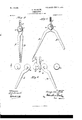
- Figure l is a face View of a pair of Compasses embodying my invention in its preferred form, the legs being closed.Y
- Fig. 3 represents the two legs and the central hand piece detached from one another.
- Figs. 4, 5, and 6 are similar views of a modiication hereinafter described.
- the two legs are shown at A B. They may be of any suitable contour and made of any suitable material, preferably cast metal or sheet metal, one of them, A, having a metal point and the other having a pencil-receiving socket and clamp like that which is the subject of my Patent No.-665,259, of .Iannary 1, 1901.
- the handpiece C is the handpiece, having its upper end of convenient shape to be taken between the fingers and its lower portion as aliat piece of metal, which is placed between the upper ends of the two legs A B, the parts being held together by the pivot-pin o, which passes throughthein, and washers n, one on each i side, the pivot-pin being headed down upon the washers.
- the handpiece C is capable of turning on the pivot-pin o just as the legs do, and as-it will be liable to follow the movement of one or the other of the legs it will thus be inclined from the vertical central position which it ought to occupy and must be brought back to that central position by hand before the Compasses can be conveniently ysaid slots it cannot escape therefrom.
- the preferred means for this purpose (shown in Figs. l, 2, and 3) consists of a curved outwardlyv and downwardly extending slot a. in the leg A, acorrespondingly shaped and ,located ⁇ slot b in leg B, a ver- 6o tical central slot c in that portion of the handpiece C below the pivot-pin o, and a pin d, which passes loosely through both slots t l) and the intermediate straight slot oA and has its ends headed, so that while it may move in o5 When the legs A B are closed, as in Fig.
- the handpiece C is vertical and the pin CZ is at thelowest ends of the three slots a b c and vertically under the pivot o.
- the pin d will rise in the slots a b c, and by reason of its engagement with these parts will-at all times maintain the handpiece in its upright central position no matter vwhat may be the spread of the compass- 7 5 legs. This I believe to be new with me beyond its particular structural embodiment herein illustrated.
- This pin While located vertically under the pivot o and corroo responding in function to the pin d in the structure illustrated in Figs. l to 3, is, however, a fixture in the handpiece and incapable ofmovement independently of the latter. Inasmuch as the pin by reason of its engagement with the legs AB must move up or down, according as they open or close, it becomes necessary to provide that the handpiece itself may be capable of such movement. To this end the handpiece atf the point where the pivot-pin 0 passes through it has a vertical slot c', (correspondingin function to lthe slot c in Figs. 1 to 3,) whereby the handpiece itself can rise and fall along with the pin d.
- the pivot-pin o is at Lhe'upper end of the slot c when the legs are closed, as in Fig. 4.
- the pin d When, however, the legs are opened, the pin d will be forced straight upwardly and the handpiece will rise with it, the slot c' permitting these movements, the parts then occupying the position shown in Fig. 5.
- compass-legs having outwardly and downwardly extending slots, a handpiece interposed between,and hung upon a common axis with, said legs, a pin engaging the handpiece and entering the slots in the compass-legs, and provisions for permitting the said pin to move in a right line up and down to 'and from the pivot, as the compasslegs are opened and closed, substantially as and for the purposes hereinbefore set forth.
Landscapes
- Surgical Instruments (AREA)
Description
, PATENTE] JUNE 9, 1903. G. OBBRBBGK;
COMPASSES.
APPLIGATION FILED JAN. 29, 1903,
2 SHEETS-SHEET 1.
N0 MODEL.
PATBNTBD JUNE 9, 190s.
G. OBBRBBGK. GoMPAssBs. APPLIGATIN FILED JAN. 29, 1903.
2 SHEBTMSHEBT 2.
` l NokMoDzL.
- UNITED? STATES PATENT Patented J' une '9, 190.
GEORGE OBERBECK, OF JERSEY CITY, NEW `JERSEY, ASSIGNOR TO EAGLE PENCIL COMPANY, OF NEW YORK, N. Y.
COMPASSES.
SPECIFIQATION formingpart of Letters Patent No. '730,388,5dated June 9, 1903. Application tiled January 29, 1903. Serial No. MLGGY. (Nortnodel.)
a vertical position in all positions of the legs,
whether the latter are closed or more or less spread apart.
I shall first describe the improvement by reference to the accompanying drawings, which illustrate compasses embodying the improvement, and will then point out in theclaims` those features of the same which I believe to be new and of my own invention. V
In the drawings, Figure l is a face View of a pair of Compasses embodying my invention in its preferred form, the legs being closed.Y
Eig. 2 is a like View of the same with the legs spread apart.v Fig. 3 represents the two legs and the central hand piece detached from one another. Figs. 4, 5, and 6 are similar views of a modiication hereinafter described.
The two legs are shown at A B. They may be of any suitable contour and made of any suitable material, preferably cast metal or sheet metal, one of them, A, having a metal point and the other having a pencil-receiving socket and clamp like that which is the subject of my Patent No.-665,259, of .Iannary 1, 1901.
C is the handpiece, having its upper end of convenient shape to be taken between the fingers and its lower portion as aliat piece of metal, which is placed between the upper ends of the two legs A B, the parts being held together by the pivot-pin o, which passes throughthein, and washers n, one on each i side, the pivot-pin being headed down upon the washers. The handpiece C is capable of turning on the pivot-pin o just as the legs do, and as-it will be liable to follow the movement of one or the other of the legs it will thus be inclined from the vertical central position which it ought to occupy and must be brought back to that central position by hand before the Compasses can be conveniently ysaid slots it cannot escape therefrom.
manipulated. To remedy this objection, I provide means bywhich the handpiece shall always be maintained in one and the same vertical central position whether the legs be open or shut. The preferred means for this purpose (shown in Figs. l, 2, and 3) consists of a curved outwardlyv and downwardly extending slot a. in the leg A, acorrespondingly shaped and ,located` slot b in leg B, a ver- 6o tical central slot c in that portion of the handpiece C below the pivot-pin o, and a pin d, which passes loosely through both slots t l) and the intermediate straight slot oA and has its ends headed, so that while it may move in o5 When the legs A B are closed, as in Fig. l, the handpiece C is vertical and the pin CZ is at thelowest ends of the three slots a b c and vertically under the pivot o. When the legs are spread 7o apart, the pin d will rise in the slots a b c, and by reason of its engagement with these parts will-at all times maintain the handpiece in its upright central position no matter vwhat may be the spread of the compass- 7 5 legs. This I believe to be new with me beyond its particular structural embodiment herein illustrated.
In the figures thus far described the pin d,
vwhose engagement with the handpiece main- 8o tains the latter in its vertical central position, rises and falls in a slot in the handpiece; but the same result can be reached by having the pin iixedly engage the handpiece, and
to make the handpiece itself capable of moving bodily up and down all that is needed being that the pin should have the capacity of moving up and down, (whether independently of or bodily with the handpiece,) so as to permit it to be actuated by the slots ct Z9 in the 9o legs. This modification is represented in Figs. 4, 5, and 6. In these figures A B are the compass-legs, and C is the handpiece. In the legs are slots o b, curved outwardly and downwardly in opposite directions, as in the other case. The handpiece has a pin d', which extends through the lower part of the handpiece and projects from each facethereof into slots a b of the legs. This pin, While located vertically under the pivot o and corroo responding in function to the pin d in the structure illustrated in Figs. l to 3, is, however, a fixture in the handpiece and incapable ofmovement independently of the latter. Inasmuch as the pin by reason of its engagement with the legs AB must move up or down, according as they open or close, it becomes necessary to provide that the handpiece itself may be capable of such movement. To this end the handpiece atf the point where the pivot-pin 0 passes through it has a vertical slot c', (correspondingin function to lthe slot c in Figs. 1 to 3,) whereby the handpiece itself can rise and fall along with the pin d. The pivot-pin o is at Lhe'upper end of the slot c when the legs are closed, as in Fig. 4. When, however, the legs are opened, the pin d will be forced straight upwardly and the handpiece will rise with it, the slot c' permitting these movements, the parts then occupying the position shown in Fig. 5.
Having described my improvement in compasses and the best way now known to me of carrying the same into practical effect, I state in conclusion lthat I do not restrict myself to the structural details hereinbefore set forth in illustration of the improvement, for manifestly the same can be varied without departure from my invention; but
What I claim' as new, 'and desire to secure by Letters Patent, is-
1. In compasses, compass-legs having outwardly and downwardly extending slots, a handpiece interposed between,and hung upon a common axis with, said legs, a pin engaging the handpiece and entering the slots in the compass-legs, and provisions for permitting the said pin to move in a right line up and down to 'and from the pivot, as the compasslegs are opened and closed, substantially as and for the purposes hereinbefore set forth.
2. In Compasses, and in combination, compass-legs and a handpiece interposed between, and pivoted upon a common axis with, said legs, slots a, b in the compass-legs, a slot c in the handpiece, and a pin d extending through and engaging all three of said slots a, b, c,
rsubstantially as and for the purposes hereinbefore set forth.
- In testimony whereof I have hereunto set my hand this 27th day of January, 1903.
GEORGE OBERBECK.
Witnesses:
SAMUEL KRAUs, P. H. BUCKMASTER.
Priority Applications (1)
| Application Number | Priority Date | Filing Date | Title |
|---|---|---|---|
| US14106703A US730388A (en) | 1903-01-29 | 1903-01-29 | Compasses. |
Applications Claiming Priority (1)
| Application Number | Priority Date | Filing Date | Title |
|---|---|---|---|
| US14106703A US730388A (en) | 1903-01-29 | 1903-01-29 | Compasses. |
Publications (1)
| Publication Number | Publication Date |
|---|---|
| US730388A true US730388A (en) | 1903-06-09 |
Family
ID=2798895
Family Applications (1)
| Application Number | Title | Priority Date | Filing Date |
|---|---|---|---|
| US14106703A Expired - Lifetime US730388A (en) | 1903-01-29 | 1903-01-29 | Compasses. |
Country Status (1)
| Country | Link |
|---|---|
| US (1) | US730388A (en) |
Cited By (7)
| Publication number | Priority date | Publication date | Assignee | Title |
|---|---|---|---|---|
| US2543138A (en) * | 1948-05-20 | 1951-02-27 | Francis E Vaughan | Compass |
| US2582585A (en) * | 1947-03-20 | 1952-01-15 | James Mfg Co Inc | Compass |
| US5090127A (en) * | 1991-03-21 | 1992-02-25 | Creative Works, L.P. | Safety compass |
| US5979066A (en) * | 1995-01-26 | 1999-11-09 | Buschle; Richard Dieter | Compass |
| USD453530S1 (en) | 2001-04-11 | 2002-02-12 | Manufacture d'Articles de Precision et de Dessin—M.A.P.E.D. | Compass |
| USD505451S1 (en) * | 2004-08-16 | 2005-05-24 | Maped | Compass |
| USD792516S1 (en) * | 2015-10-01 | 2017-07-18 | Maped | Compass head |
-
1903
- 1903-01-29 US US14106703A patent/US730388A/en not_active Expired - Lifetime
Cited By (7)
| Publication number | Priority date | Publication date | Assignee | Title |
|---|---|---|---|---|
| US2582585A (en) * | 1947-03-20 | 1952-01-15 | James Mfg Co Inc | Compass |
| US2543138A (en) * | 1948-05-20 | 1951-02-27 | Francis E Vaughan | Compass |
| US5090127A (en) * | 1991-03-21 | 1992-02-25 | Creative Works, L.P. | Safety compass |
| US5979066A (en) * | 1995-01-26 | 1999-11-09 | Buschle; Richard Dieter | Compass |
| USD453530S1 (en) | 2001-04-11 | 2002-02-12 | Manufacture d'Articles de Precision et de Dessin—M.A.P.E.D. | Compass |
| USD505451S1 (en) * | 2004-08-16 | 2005-05-24 | Maped | Compass |
| USD792516S1 (en) * | 2015-10-01 | 2017-07-18 | Maped | Compass head |
Similar Documents
| Publication | Publication Date | Title |
|---|---|---|
| US2489553A (en) | Adjustable support | |
| US730388A (en) | Compasses. | |
| US1769076A (en) | Garment hanger | |
| US1618088A (en) | Purse | |
| US1694470A (en) | Combination trunk | |
| US794409A (en) | Combined rule and square. | |
| US556840A (en) | Square | |
| USD153828S (en) | Design for a folding jewel chest | |
| US810729A (en) | Skirt-supporter. | |
| US357487A (en) | Combined squared calipers | |
| US851258A (en) | Baby-waist. | |
| USD136131S (en) | Design for a folding utility case | |
| US813415A (en) | Tailor's measure. | |
| USD73704S (en) | Design for a combination bench and wardrobe | |
| USD80621S (en) | Edward j | |
| USD72540S (en) | Design for an ash tray ob, article of similar nature | |
| USD171984S (en) | Levine support for a luggage handle | |
| US1520450A (en) | Cutter clearance gauge | |
| US774327A (en) | Drawing-compasses. | |
| US572739A (en) | Daniel b | |
| US671545A (en) | Cuff-holder. | |
| USD40606S (en) | Jacob k | |
| US1624788A (en) | Combination | |
| USD84216S (en) | Abraham sttderov | |
| USD173319S (en) | Cake tray or similar article |