US7276219B2 - Preparation of 157nm transmitting barium fluoride crystals with permeable graphite - Google Patents
Preparation of 157nm transmitting barium fluoride crystals with permeable graphite Download PDFInfo
- Publication number
- US7276219B2 US7276219B2 US10/981,889 US98188904A US7276219B2 US 7276219 B2 US7276219 B2 US 7276219B2 US 98188904 A US98188904 A US 98188904A US 7276219 B2 US7276219 B2 US 7276219B2
- Authority
- US
- United States
- Prior art keywords
- subgrain
- fluoride
- crystal
- optical
- transmission
- Prior art date
- Legal status (The legal status is an assumption and is not a legal conclusion. Google has not performed a legal analysis and makes no representation as to the accuracy of the status listed.)
- Expired - Fee Related, expires
Links
- 239000013078 crystal Substances 0.000 title claims abstract description 124
- 229910001632 barium fluoride Inorganic materials 0.000 title claims description 64
- OYLGJCQECKOTOL-UHFFFAOYSA-L barium fluoride Chemical compound [F-].[F-].[Ba+2] OYLGJCQECKOTOL-UHFFFAOYSA-L 0.000 title claims description 48
- OKTJSMMVPCPJKN-UHFFFAOYSA-N Carbon Chemical compound [C] OKTJSMMVPCPJKN-UHFFFAOYSA-N 0.000 title description 51
- 229910002804 graphite Inorganic materials 0.000 title description 49
- 239000010439 graphite Substances 0.000 title description 49
- 238000002360 preparation method Methods 0.000 title description 11
- 230000003287 optical effect Effects 0.000 claims abstract description 38
- 230000005540 biological transmission Effects 0.000 claims abstract description 33
- KRHYYFGTRYWZRS-UHFFFAOYSA-M Fluoride anion Chemical compound [F-] KRHYYFGTRYWZRS-UHFFFAOYSA-M 0.000 claims abstract description 30
- 229910001512 metal fluoride Inorganic materials 0.000 claims abstract 4
- 230000007547 defect Effects 0.000 claims description 12
- 238000001459 lithography Methods 0.000 claims description 4
- 238000004519 manufacturing process Methods 0.000 abstract description 6
- 238000000034 method Methods 0.000 description 35
- 239000012025 fluorinating agent Substances 0.000 description 34
- 230000008569 process Effects 0.000 description 28
- WUKWITHWXAAZEY-UHFFFAOYSA-L calcium difluoride Chemical compound [F-].[F-].[Ca+2] WUKWITHWXAAZEY-UHFFFAOYSA-L 0.000 description 24
- 230000035699 permeability Effects 0.000 description 22
- 229910001634 calcium fluoride Inorganic materials 0.000 description 21
- 239000000463 material Substances 0.000 description 20
- FPHIOHCCQGUGKU-UHFFFAOYSA-L difluorolead Chemical compound F[Pb]F FPHIOHCCQGUGKU-UHFFFAOYSA-L 0.000 description 17
- 239000000203 mixture Substances 0.000 description 13
- 239000012535 impurity Substances 0.000 description 12
- 239000007858 starting material Substances 0.000 description 12
- 238000001816 cooling Methods 0.000 description 10
- 239000002994 raw material Substances 0.000 description 10
- 238000002844 melting Methods 0.000 description 8
- 230000008018 melting Effects 0.000 description 8
- 150000001340 alkali metals Chemical class 0.000 description 6
- QVGXLLKOCUKJST-UHFFFAOYSA-N atomic oxygen Chemical compound [O] QVGXLLKOCUKJST-UHFFFAOYSA-N 0.000 description 6
- 239000006185 dispersion Substances 0.000 description 6
- 229910052760 oxygen Inorganic materials 0.000 description 6
- 239000001301 oxygen Substances 0.000 description 6
- 238000010521 absorption reaction Methods 0.000 description 5
- 230000008901 benefit Effects 0.000 description 5
- ODINCKMPIJJUCX-UHFFFAOYSA-N calcium oxide Inorganic materials [Ca]=O ODINCKMPIJJUCX-UHFFFAOYSA-N 0.000 description 5
- 238000002425 crystallisation Methods 0.000 description 5
- 238000000206 photolithography Methods 0.000 description 5
- 150000002222 fluorine compounds Chemical class 0.000 description 4
- 238000010438 heat treatment Methods 0.000 description 4
- 239000012768 molten material Substances 0.000 description 4
- 239000011148 porous material Substances 0.000 description 4
- 239000000843 powder Substances 0.000 description 4
- 239000007787 solid Substances 0.000 description 4
- 229910052783 alkali metal Inorganic materials 0.000 description 3
- 229910001515 alkali metal fluoride Inorganic materials 0.000 description 3
- 229910052784 alkaline earth metal Inorganic materials 0.000 description 3
- 229910001618 alkaline earth metal fluoride Inorganic materials 0.000 description 3
- 150000001342 alkaline earth metals Chemical class 0.000 description 3
- 239000000292 calcium oxide Substances 0.000 description 3
- BRPQOXSCLDDYGP-UHFFFAOYSA-N calcium oxide Chemical compound [O-2].[Ca+2] BRPQOXSCLDDYGP-UHFFFAOYSA-N 0.000 description 3
- 238000006243 chemical reaction Methods 0.000 description 3
- 238000000576 coating method Methods 0.000 description 3
- 238000011068 loading method Methods 0.000 description 3
- VYPSYNLAJGMNEJ-UHFFFAOYSA-N Silicium dioxide Chemical compound O=[Si]=O VYPSYNLAJGMNEJ-UHFFFAOYSA-N 0.000 description 2
- 230000004075 alteration Effects 0.000 description 2
- LDDQLRUQCUTJBB-UHFFFAOYSA-N ammonium fluoride Chemical compound [NH4+].[F-] LDDQLRUQCUTJBB-UHFFFAOYSA-N 0.000 description 2
- 238000004458 analytical method Methods 0.000 description 2
- 239000011324 bead Substances 0.000 description 2
- 239000011575 calcium Substances 0.000 description 2
- 238000007599 discharging Methods 0.000 description 2
- 239000003344 environmental pollutant Substances 0.000 description 2
- 239000005350 fused silica glass Substances 0.000 description 2
- 230000014759 maintenance of location Effects 0.000 description 2
- 238000012986 modification Methods 0.000 description 2
- 230000004048 modification Effects 0.000 description 2
- 231100000719 pollutant Toxicity 0.000 description 2
- 229920001343 polytetrafluoroethylene Polymers 0.000 description 2
- 239000004810 polytetrafluoroethylene Substances 0.000 description 2
- 239000004065 semiconductor Substances 0.000 description 2
- 238000007711 solidification Methods 0.000 description 2
- 230000008023 solidification Effects 0.000 description 2
- BHHYHSUAOQUXJK-UHFFFAOYSA-L zinc fluoride Chemical compound F[Zn]F BHHYHSUAOQUXJK-UHFFFAOYSA-L 0.000 description 2
- OYPRJOBELJOOCE-UHFFFAOYSA-N Calcium Chemical compound [Ca] OYPRJOBELJOOCE-UHFFFAOYSA-N 0.000 description 1
- YCKRFDGAMUMZLT-UHFFFAOYSA-N Fluorine atom Chemical compound [F] YCKRFDGAMUMZLT-UHFFFAOYSA-N 0.000 description 1
- 229920006362 Teflon® Polymers 0.000 description 1
- 238000000137 annealing Methods 0.000 description 1
- 229910052791 calcium Inorganic materials 0.000 description 1
- 229910052799 carbon Inorganic materials 0.000 description 1
- 239000007795 chemical reaction product Substances 0.000 description 1
- 239000003795 chemical substances by application Substances 0.000 description 1
- 239000011248 coating agent Substances 0.000 description 1
- 230000000052 comparative effect Effects 0.000 description 1
- 239000000356 contaminant Substances 0.000 description 1
- 238000001514 detection method Methods 0.000 description 1
- 238000009826 distribution Methods 0.000 description 1
- 230000000694 effects Effects 0.000 description 1
- 238000000921 elemental analysis Methods 0.000 description 1
- 230000008030 elimination Effects 0.000 description 1
- 238000003379 elimination reaction Methods 0.000 description 1
- 238000005516 engineering process Methods 0.000 description 1
- 229910052731 fluorine Inorganic materials 0.000 description 1
- 239000011737 fluorine Substances 0.000 description 1
- 238000009472 formulation Methods 0.000 description 1
- 239000007789 gas Substances 0.000 description 1
- 229910021397 glassy carbon Inorganic materials 0.000 description 1
- 230000010354 integration Effects 0.000 description 1
- 238000001393 microlithography Methods 0.000 description 1
- 238000002156 mixing Methods 0.000 description 1
- -1 polytetrafluoroethylene Polymers 0.000 description 1
- 239000000047 product Substances 0.000 description 1
- 230000005855 radiation Effects 0.000 description 1
- 230000000717 retained effect Effects 0.000 description 1
- 238000001228 spectrum Methods 0.000 description 1
- 229910001637 strontium fluoride Inorganic materials 0.000 description 1
- FVRNDBHWWSPNOM-UHFFFAOYSA-L strontium fluoride Chemical compound [F-].[F-].[Sr+2] FVRNDBHWWSPNOM-UHFFFAOYSA-L 0.000 description 1
- 239000000126 substance Substances 0.000 description 1
- 238000000411 transmission spectrum Methods 0.000 description 1
- XLYOFNOQVPJJNP-UHFFFAOYSA-N water Substances O XLYOFNOQVPJJNP-UHFFFAOYSA-N 0.000 description 1
Images


Classifications
-
- C—CHEMISTRY; METALLURGY
- C30—CRYSTAL GROWTH
- C30B—SINGLE-CRYSTAL GROWTH; UNIDIRECTIONAL SOLIDIFICATION OF EUTECTIC MATERIAL OR UNIDIRECTIONAL DEMIXING OF EUTECTOID MATERIAL; REFINING BY ZONE-MELTING OF MATERIAL; PRODUCTION OF A HOMOGENEOUS POLYCRYSTALLINE MATERIAL WITH DEFINED STRUCTURE; SINGLE CRYSTALS OR HOMOGENEOUS POLYCRYSTALLINE MATERIAL WITH DEFINED STRUCTURE; AFTER-TREATMENT OF SINGLE CRYSTALS OR A HOMOGENEOUS POLYCRYSTALLINE MATERIAL WITH DEFINED STRUCTURE; APPARATUS THEREFOR
- C30B11/00—Single-crystal growth by normal freezing or freezing under temperature gradient, e.g. Bridgman-Stockbarger method
- C30B11/002—Crucibles or containers for supporting the melt
-
- C—CHEMISTRY; METALLURGY
- C30—CRYSTAL GROWTH
- C30B—SINGLE-CRYSTAL GROWTH; UNIDIRECTIONAL SOLIDIFICATION OF EUTECTIC MATERIAL OR UNIDIRECTIONAL DEMIXING OF EUTECTOID MATERIAL; REFINING BY ZONE-MELTING OF MATERIAL; PRODUCTION OF A HOMOGENEOUS POLYCRYSTALLINE MATERIAL WITH DEFINED STRUCTURE; SINGLE CRYSTALS OR HOMOGENEOUS POLYCRYSTALLINE MATERIAL WITH DEFINED STRUCTURE; AFTER-TREATMENT OF SINGLE CRYSTALS OR A HOMOGENEOUS POLYCRYSTALLINE MATERIAL WITH DEFINED STRUCTURE; APPARATUS THEREFOR
- C30B11/00—Single-crystal growth by normal freezing or freezing under temperature gradient, e.g. Bridgman-Stockbarger method
-
- C—CHEMISTRY; METALLURGY
- C30—CRYSTAL GROWTH
- C30B—SINGLE-CRYSTAL GROWTH; UNIDIRECTIONAL SOLIDIFICATION OF EUTECTIC MATERIAL OR UNIDIRECTIONAL DEMIXING OF EUTECTOID MATERIAL; REFINING BY ZONE-MELTING OF MATERIAL; PRODUCTION OF A HOMOGENEOUS POLYCRYSTALLINE MATERIAL WITH DEFINED STRUCTURE; SINGLE CRYSTALS OR HOMOGENEOUS POLYCRYSTALLINE MATERIAL WITH DEFINED STRUCTURE; AFTER-TREATMENT OF SINGLE CRYSTALS OR A HOMOGENEOUS POLYCRYSTALLINE MATERIAL WITH DEFINED STRUCTURE; APPARATUS THEREFOR
- C30B29/00—Single crystals or homogeneous polycrystalline material with defined structure characterised by the material or by their shape
- C30B29/10—Inorganic compounds or compositions
- C30B29/12—Halides
Definitions
- the present invention relates generally to the preparation of fluoride crystals, and particularly to making of barium fluoride crystals with improved below 175 nm wavelength optical properties.
- said invention relates:
- Ultra-high performance optical systems are required in order to increase the density of integration of the electronic components on a semi-conductor plate and insofar as exposed light of low wavelength (lower than 248 nm) is necessary in order to improve the resolution.
- the most common technique up to now for obtaining such optical systems uses fused silica.
- Ultra-high performance far-ultraviolet optical systems with below 175 nm wavelengths would benefit from highly transmitting barium fluoride optical crystals.
- the present invention overcomes problems in the prior art and provides a means for economically providing high quality 157 nm transmitting fluoride crystal blanks for optical lithography lens element blanks that can be used to improve the manufacturing of integrated circuits with 157 nm vacuum ultraviolet wavelengths.
- Said crystals comprised of barium fluoride are in principle obtained according to the process known as the Stockbarger-Bridgman process, which is familiar to the person skilled in the art.
- the crystal is generated from a molten starting material crystal feedstock in slowly lowering (generally at a speed between 0.3 and 5 mm/h, more generally between 1 and 3 mm/h) a crucible (or a stack of crucibles) containing said molten material through a solidification zone which is provided in an oven.
- the crucible(s) is (are) made from a material which is resistant to chemical attack from the material that it contains. In general, it is (a) crucible(s) in graphite of high purity.
- the graphite does have the drawback of being porous (of being a material having open porosity), and it is recommended to coat the internal walls of such graphite crucibles with an appropriate internal coating, in order to block the porosity of said walls.
- the crystals are preferably prepared in the absence of water, of air and of any other source of oxygen. They are thus generally prepared under vacuum in the presence of a fluorinating agent. Said fluorinating agent provides for the elimination of oxygen, especially of that introduced in the form of oxide as impurity in the starting material crystal feedstock.
- PbF 2 is the most utilised fluorinating agent, insofar as its manipulation does not present any particular difficulty, insofar as it is solid at ambient temperature and insofar as it has, itself and its corresponding oxide (PbO), a high vapour pressure at the temperatures of use of crystallisation ovens. Said PbF 2 acts, within the context of the preparation of CaF 2 crystals, notably according to the reaction: CaO+PbF 2 ⁇ CaF 2 +PbO.
- One aspect of the invention relates to a process of preparing a barium fluoride optical crystal which includes loading a crucible with a mixture of a barium fluoride optical crystal starting material crystal, feedstock which contains at least one oxide as impurity, and an effective and non-excess amount of at least one fluorinating agent which is solid at ambient temperature, melting said mixture within said crucible, growing the barium fluoride crystal, by controlled cooling of the barium fluoride molten mixture, controlled cooling of said barium fluoride crystal to ambient temperature, and recovering said barium fluoride crystal wherein the oxide(s) resulting from the reaction between said fluorinating agent(s) and said oxide(s), the impurity or impurities, and the fluorinating agent components (particularly lead from lead fluoride) can be discharged from said crucible, in view of the crucible and the intrinsic permeability of the material constituting it.
- the present invention includes a method of making an optical barium fluoride crystal with increased below 170 nm transmission by providing a barium fluoride crystal producing permeable graphite crucible for containing the barium fluoride, said permeable graphite crucible comprised of a permeable graphite having a permeability of which, measured according to the DIN 51935 Standard, is greater than 4 cm 2 /s, forming a molten barium fluoride melt in said graphite crucible comprised of said graphite having a permeability greater than 4 cm 2 /s and forming a barium fluoride crystal from said molten fluoride melt, said formed barium fluoride crystal having an increased far-ultraviolet transmission with intrinsic internal transmission at 157 nm ⁇ 99% per cm.
- the present invention includes an optical barium fluoride crystal producing graphite crucible for making an optical barium fluoride crystal with increased 157 nm transmission, said graphite crucible comprised of a graphite having a permeability of which, measured according to the DIN 51935 Standard, is greater than 4 cm 2 /s, preferably the graphite has a permeability in the range of 5 to 15 cm 2 /s.
- the invention comprises a barium fluoride crystalline optical lithography lens element blank with 157 nm transmission above 99%/cm and preferably with large dimension diameters greater than 300 mm.
- the barium fluoride crystalline optical element blank includes crystalline subgrains which have crystalline subgrain structures.
- the barium fluoride crystalline optical element blank includes at least a first subgrain structure and a second subgrain structure.
- the second subgrain structure is adjacent to and abuts the first subgrain structure at a first defect boundary formed by dislocation defects.
- the first defect boundary has an adjacent first subgrain-second subgrain boundary angle.
- the first subgrain-second subgrain boundary angle is less than two minutes and the blank has an impurity level less than 0.2 ppm Pb by weight.
- the barium fluoride crystal has a 157 nm internal transmission of at least 99.2%/cm.
- the invention includes a method of making a barium fluoride crystalline optical lithography lens element blank.
- the method of making includes forming a barium fluoride crystalline melt from a barium fluoride feedstock with less than 150 ppm of oxygen in a machined crucible of permeable graphite, crystallizing the barium fluoride melt into a barium fluoride crystalline member preferably with a large dimension ⁇ 200 mm, and annealing the fluoride crystalline member.
- the method further includes qualifying the annealed fluoride crystalline member to provide a fluoride crystalline optical lithography lens element blank with a 157 nm internal absorption coefficient less than 0.0022/cm and a maximum surface subgrain disorientation boundary angle ⁇ 2 minutes.
- FIG. 1 shows an embodiment of the invention.
- FIG. 2 shows an embodiment of the invention.
- FIG. 3 shows an embodiment of the invention.
- FIG. 4 shows an embodiment of the invention.
- FIG. 5 shows an embodiment of the invention.
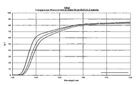
- FIG. 6 illustrates the deep UV transmision of BaF 2 sample No. 6-2 that is described in Table 3.
- the process of preparing a crystal of the invention comprises:
- said crucible is in general loaded with a mixture de synthetic CaF 2 powder, which contains CaO as impurity, and PbF 2 (fluorinating agent).
- the crucible in question can very well not be a single one.
- the process of the invention can effectively be carried out, just as the process of the prior art, with a stack of n crucibles, which is moved with a translatory motion along its vertical axis.
- the fluorinating agent(s) which is (are) incorporated is (are) not incorporated in an excess amount. In this way, it (they) cannot pollute the crystals prepared.
- the oxide(s) (PbO in the context specified above (in a purely illustrative manner) of preparation of (mono)crystals of CaF 2 ) resulting from the reaction between said fluorinating agent(s) (PbF 2 ) and said oxide(s), the impurity or impurities (CaO), can be discharged from said crucible, in view of the dimensions of said crucible and of the intrinsic permeability of the material constituting it.
- the crucible(s) which intervene(s) for carrying out the process of the invention is (are) optimised, as to its (their) size and its (their) intrinsic permeability, such that the crystals prepared no longer contain—in any case, less than 0.1 ppm—any element corresponding to the formulation of the fluorinating agents (element Pb, in the context specified above (in a purely illustrative manner) of preparation of (mono)crystals of CaF 2 , with intervention of PbF 2 as fluorinating agent).
- element Pb in the context specified above (in a purely illustrative manner) of preparation of (mono)crystals of CaF 2 , with intervention of PbF 2 as fluorinating agent).
- the fluorinating agent (even the fluorinating agents) acts (act) and leave no trace.
- the fluorinating agent(s) react and the reaction products can discharge totally. There is thus no pollution of the crystals prepared.
- the permeability of a porous material is a parameter which is perfectly defined by the DIN 51935 Standard: 1993-08 (entitled “Determination of the coefficient of permeability by means of the vacuum—decay method with air as experimental gas”), which is familiar to the person skilled in the art.
- Said permeability which is generally expressed in cm 2 /s, is in fact the resultant of several factors which relate to the porosity, such as:
- the process of the invention thus enables very pure crystals to be prepared (less than 0.1 ppm of contaminant in general, and especially less than 0.1 ppm of Pb when PbF 2 is used as fluorinating agent), insofar as the discharging of the impurities, which are generated following the intervention of the fluorinating agents, is mastered perfectly.
- the mastering of this discharging is based jointly on the dimensions of the crucible in question (said dimensions are inevitably limited such that the vapours have the possibility of diffusing (and of being discharged) within the molten material before its crystallisation (its solidification) and on the permeability of the material constituting said crucible.
- vapours in question diffuse within the molten material and discharge through the permeable walls of the crucible and through the surface of said molten material.
- said amount is rarely greater than 5% by weight of the starting material crystal feedstock which intervenes, that it is advantageously between 0.1 and 2% by weight of said starting material crystal feedstock.
- said fluorinating agent(s) is (are) selected from: PbF 2 , ZnF 2 , NH 4 F, NH 4 F.HF, PTFE (polytetrafluoroethylene: Teflon®), and mixtures thereof. It has already been seen, in the introduction of the present text, that PbF 2 is the most used fluorinating agent up to now. Its intervention is particularly recommended within the context of the present invention.
- the high permeability graphite crucible that are comprised of graphite having a DIN Standard (DIN 51935) greater than 4 cm 2 /s are utilized in conjunction with a gaseous fluorinating agent such as CF 4 .
- a gaseous fluorinating agent such as CF 4 .
- said crucible(s) is (are) in a graphite, the permeability of which, in accordance with the same Standard, is greater than 10 cm 2 /s.
- the material constituting the crucibles used is not forced to be graphite, but, obviously, said material is adapted to the constraints of the process carried out within it (presence of corrosive products, high temperatures . . . ).
- the pollutant oxide(s) generated during the crystallisation within the crystallisation crucible is (are), according to the invention, capable of being discharged from said crucible, by virtue of the dimensions of said crucible and the permeability of the material constituting it (them).
- the process of the invention is particularly suitable for preparing (mono)crystals of alkali metal and/or alkaline-earth metal fluorides. It enables the preparation of (mono)crystals, which are very pure, of alkali metal or alkaline-earth metal fluorides, and even the preparation of mixed (mono)crystals of fluorides of alkali metals and/or alkaline-earth metals, which are very pure, (mixtures of at least two alkali metals, of at least two alkaline-earth metals or of at least one alkali metal and at least one alkaline-earth metal).
- (mono)crystals of fluorides have been prepared of high optical quality; especially (mono)crystals of calcium and barium fluorides which have, at the wavelengths ( ⁇ ) indicated below, the intrinsic transmissions (T i ) specified below:
- Such monocrystals have obvious potential in laser and lithography industries.
- the process of the invention is more particularly suitable for preparing (mono)crystals of calcium fluoride (CaF 2 ).
- the process of the invention is advantageously carried out with a stack of crucibles, according to the Stockbarger-Bridgman method, i.e. that in its context, the controlled cooling of the molten mixture (for growing the (mono)crystals) is obtained by very slowly moving a stack of loaded crucibles from the top to the bottom, from a hot zone to a cold zone, of an oven having a vertical axis.
- the process of the invention is very advantageously carried out according to the improved Stockbarger-Bridgman method, as described in the French patent application FR 00 03 771 (24th Mar. 2000) not published as yet, i.e. with a translatory motion of the stack of loaded crucibles, continuously, the operations of loading of said crucibles being carried out without stopping the translatory motion (along the vertical axis) of the stack of crucibles.
- Said process of the invention is classically carried out with starting material crystal feedstock in the form of a powder, especially a synthetic powder (e.g. CaF 2 ). It may also advantageously be carried out with starting material crystal feedstock which intervenes in the form of beads.
- a synthetic powder e.g. CaF 2
- starting material crystal feedstock which intervenes in the form of beads.
- the process of the invention is advantageously carried out for preparing (mono)crystals of calcium fluoride (CaF 2 ), in the presence of PbF 2 (fluorinating agent); said calcium fluoride (starting material crystal feedstock) containing calcium oxide (CaO) as impurity.
- the process of the invention is advantageously carried out for preparing (mono)crystals of calcium fluoride (CaF 2 ), in the presence of CF 4 (gaseous fluorinating agent); said calcium fluoride (starting material crystal feedstock) containing calcium oxide (CaO) as impurity.
- CF 4 gaseous fluorinating agent
- the Stockbarger-Bridgman process was carried out, starting with synthetic CaF 2 powder, under the same conditions, in using graphite crucibles (stacks of such crucibles); the graphites (type A to D) not having the same characteristics.
- the crucibles used had the same geometry (cylindrical) and the same dimensions: 200 mm diameter for 50 mm height.
- the process of the invention was carried out with crucibles in graphite of type C and D.
- the crystals obtained were analysed chemically with the view to determining their lead (Pb) content.
- the inventors have themselves carried out considerable experimental work before identifying the critical parameter—the intrinsic permeability of the material constituting the crucible, the dimensions of said crucible being fixed—.
- the inventors have especially demonstrated that the means of implementation of the heating cycle (with the view to obtaining the melting of the starting material crystal feedstock) was not itself critical. This is the subject of the Comparative Example below.
- Graphite crucibles having the dimensions indicated in Example I, of type A and C were used (in stacks) to prepare crystals according to the Stockbarger-Bridgman method. Said method was carried out with different temperature rise cycles which are specified in Table II below.
- the increased far-ultraviolet transmission fluoride optical crystal producing graphite crucible is comprised of a graphite having a permeability of which, measured according to the DIN 51935 Standard, is greater than 4 cm 2 /s.
- the graphite permeability is greater than 5 cm 2 /s, more preferably greater than 6 cm 2 /s, more preferably greater than 7 cm 2 /s, more preferably greater than 8 cm 2 /s, more preferably greater than 9 cm 2 /s, more preferably greater than 10 cm 2 /s, more preferably greater than 11 cm 2 /s, more preferably greater than 12 cm 2 /s, more preferably greater than 13 cm 2 /s, more preferably greater than 14 cm 2 /s.
- the increased far-ultraviolet transmission fluoride optical crystal producing graphite crucible is comprised of a graphite having a Hg porosity of at least 16.7%, more preferably at least 17%, more preferably at least 18%, more preferably at least 19%, and more preferably a Hg porosity of at least 20%.
- Optical fluoride crystals comprised of barium fluoride are of interest for use in potential 157 nm lithography and laser systems. Barium Fluoride crystals are attractive materials for 157 nm photolithography.
- the interest in BaF 2 optical fluoride crystals stems from two possible functions in the stepper system. The first is for correction of chromatic aberration (color correction) and the second is correction of intrinsic birefringence.
- optical fluoride crystals comprised of barium fluoride are of interest is that mixed optical fluoride crystals including barium fluoride provide the potential of avoiding intrinsic birefringence at 157 nm, such as with a mixed optical fluoride crystal including barium fluoride and calcium fluoride.
- Chromatic aberration arises from the dependence on wavelength of the refractive index in a given material.
- Excimer laser sources have a finite bandwidth (about 1 pm at 157 nm), and therefore each component of the bandwidth “sees” a different refractive index. In refractive systems this leads to defocusing of the image on the wafer.
- One can correct for this by introducing a second material with a different dispersion than the first. At 193 nm color correction is achieved by matching the dispersion of CaF 2 and fused silica.
- BaF 2 is the likeliest alternative for a second material at 157 nm as it shares many of the attributes of CaF 2 : it has a band edge below 140 nm, it has cubic symmetry, it is stable, can be polished, and can be grown in large size (Table Dispersion of alkaline-earth fluorides).
- Crystals were grown in Stockbarger-Bridgeman crystal vacuum furnaces, an example of which is shown in FIG. 1 which can grow crystals up to 320 mm ⁇ 50 mm.
- Stockbarger-Bridgeman crystal vacuum furnaces were used for pretreatment of raw materials in batches up to 40 kg.
- Stockbarger-Bridgeman crystal vacuum furnaces were used to grow 64 mm rods for raw materials testing.
- the invention provides BaF 2 crystals with diameter of >300 mm grown with 157 nm transmission above 99 %/cm.
- Elemental analyses of BaF2 Raw Materials are shown in Table I—Analysis of BaF2 Raw Materials.
- a preferred BaF2 raw material contains less than 150 ppm oxygen, preferably less than 120 ppm oxygen. Oxygen content in the material A is estimated at greater than 2000 ppm.
- Crystals were grown in stacked graphite crucibles with the top crucible covered by a graphite plate. The entire stack was housed in a graphite container. Two types of graphite were used. Low permeable graphite (less than 4 cm 2 /s) was used for runs 1 through 3 . Machined permeable graphite crucibles were used for runs 4 through 8 .
- the melting point of BaF2 is about 1368° C.; about 50° C. lower than that of CaF2.
- Pretreatment Raw material pretreatment was carried out in 40 kg batches in a Stockbarger-Bridgeman crystal vacuum furnace. The raw material were mixed with 3 wt. % PbF2 and loaded into stacked graphite crucibles. The heating profile is shown in FIG. 2 . Subsequent to pretreatment, 6 mm transmission samples are evaluated on a VUV spectrophotometer. Transmission spectra are shown in FIG. 3 . Note that only runs 6 , 7 , 10 , 14 , and 15 used virgin raw material. Pretreated densified purified barium fluoride crystal feedstock preferably has a 145 nm transmission >50%.
- FIG. 5 we show the VUV spectrum of 50 mm crystals from runs 3 , 6 , and 8 .
- the 157 nm internal transmission values calculated from MPL sets are given in Table 4.
- the invention provides for the growth of BaF2 crystals with 157 nm internal transmission >99 %/cm.
- the result obtained is especially interesting owing to the very large crystal size (320 mm).
- PbF2 fluorinating agent was used, and the invention provides for obtaining high required 157 nm transmission in optical fluoride crystals using Pb-based fluorinating agent technology. This is underscored by the lower melting point of BaF2 with respect to CaF2.
- the volatility of PbF2 is lower during BaF2 crystal growth conditions.
- the absence of Pb in the resulting crystals shows the benefit of using permeable graphite in the growth of optical fluoride crystals.
Landscapes
- Chemical & Material Sciences (AREA)
- Engineering & Computer Science (AREA)
- Crystallography & Structural Chemistry (AREA)
- Materials Engineering (AREA)
- Metallurgy (AREA)
- Organic Chemistry (AREA)
- Inorganic Chemistry (AREA)
- Crystals, And After-Treatments Of Crystals (AREA)
- Compounds Of Alkaline-Earth Elements, Aluminum Or Rare-Earth Metals (AREA)
Abstract
The present invention is directed to a method of making large diameter metal fluoride sungle crystals that can be used in optical lithograpby systems, for example, excimer laser that operate below 200 nm. In addition, the invention is directed to metal fluoride single crystals suitable for use in such lithographic ststems, such fluoride crystals having a internal transmission of ≧99.9% at 193 nm and ≧99.0% at 157 nm.
Description
This application is a divisional application and claims the priority of U.S. application No. 10/113,449, filed Mar. 28, 2002, which is titled “PREPARATION OF 157NM TRANSMITTING BARIUM FLUORIDE CRYSTALS WITH PERMEABLE GRAPHITE ”; and thus application further claims the priority and benefit of French Application No. 01 044232, filed Mar. 29, 2001 by M. Meyer-Fredholm and titled “Preparation of (mono)crystal”.
The present invention relates generally to the preparation of fluoride crystals, and particularly to making of barium fluoride crystals with improved below 175 nm wavelength optical properties.
More specifically, said invention relates:
to a process of preparing barium fluoride crystals, which is improved with reference to the purity of the crystals prepared with a permeable graphite crucible; and
to a process of preparing barium fluoride crystals in permeable graphite crucibles with the resulting barium fluoride crystals having an increased transmission in the far-ultraviolet (λ<170 nm) at about the 157 nm wavelength of the fluorine excimer laser output.
Ultra-high performance optical systems are required in order to increase the density of integration of the electronic components on a semi-conductor plate and insofar as exposed light of low wavelength (lower than 248 nm) is necessary in order to improve the resolution. The most common technique up to now for obtaining such optical systems uses fused silica. Ultra-high performance far-ultraviolet optical systems with below 175 nm wavelengths would benefit from highly transmitting barium fluoride optical crystals.
Slow progression by the semiconductor industry of the use of VUV light below 175 nm such as the 157 nm region light has been due to the lack of economically manufacturable high optically transmissive fluoride blanks and difficulties in manufacturing fluoride crystals which can be identified as high quality and qualified for their intended microlithography use. The present invention overcomes problems in the prior art and provides a means for economically providing high quality 157 nm transmitting fluoride crystal blanks for optical lithography lens element blanks that can be used to improve the manufacturing of integrated circuits with 157 nm vacuum ultraviolet wavelengths.
Said crystals comprised of barium fluoride are in principle obtained according to the process known as the Stockbarger-Bridgman process, which is familiar to the person skilled in the art. According to said process, the crystal is generated from a molten starting material crystal feedstock in slowly lowering (generally at a speed between 0.3 and 5 mm/h, more generally between 1 and 3 mm/h) a crucible (or a stack of crucibles) containing said molten material through a solidification zone which is provided in an oven. The crucible(s) is (are) made from a material which is resistant to chemical attack from the material that it contains. In general, it is (a) crucible(s) in graphite of high purity.
According to the teaching of U.S. Pat. Nos. 5,911,824 and 6,093,245, the graphite does have the drawback of being porous (of being a material having open porosity), and it is recommended to coat the internal walls of such graphite crucibles with an appropriate internal coating, in order to block the porosity of said walls. Carbon coatings, especially pyrolytic or vitreous carbon coatings, are described.
The crystals are preferably prepared in the absence of water, of air and of any other source of oxygen. They are thus generally prepared under vacuum in the presence of a fluorinating agent. Said fluorinating agent provides for the elimination of oxygen, especially of that introduced in the form of oxide as impurity in the starting material crystal feedstock. PbF2 is the most utilised fluorinating agent, insofar as its manipulation does not present any particular difficulty, insofar as it is solid at ambient temperature and insofar as it has, itself and its corresponding oxide (PbO), a high vapour pressure at the temperatures of use of crystallisation ovens. Said PbF2 acts, within the context of the preparation of CaF2 crystals, notably according to the reaction:
CaO+PbF2→CaF2+PbO.
CaO+PbF2→CaF2+PbO.
In practice, it is always delicate to optimise the intervention of said fluorinating agent. It is especially critical:
to adjust the rise in temperature of the mixture (for its melting) with the view to said optimisation;
to adjust the amount of said fluorinating agent, with the view to minimising any retention of Pb or other (according to the nature of said fluorinating agent in question) in the crystal prepared: such a retention has obviously disadvantageous repercussions on the performances of transmission and resistance to radiation of said crystal.
It is, within the context set forth above, with reference to the optimisation of the intervention of fluorinating agents, that the present invention has been developed.
One aspect of the invention relates to a process of preparing a barium fluoride optical crystal which includes loading a crucible with a mixture of a barium fluoride optical crystal starting material crystal, feedstock which contains at least one oxide as impurity, and an effective and non-excess amount of at least one fluorinating agent which is solid at ambient temperature, melting said mixture within said crucible, growing the barium fluoride crystal, by controlled cooling of the barium fluoride molten mixture, controlled cooling of said barium fluoride crystal to ambient temperature, and recovering said barium fluoride crystal wherein the oxide(s) resulting from the reaction between said fluorinating agent(s) and said oxide(s), the impurity or impurities, and the fluorinating agent components (particularly lead from lead fluoride) can be discharged from said crucible, in view of the crucible and the intrinsic permeability of the material constituting it.
In another embodiment, the present invention includes a method of making an optical barium fluoride crystal with increased below 170 nm transmission by providing a barium fluoride crystal producing permeable graphite crucible for containing the barium fluoride, said permeable graphite crucible comprised of a permeable graphite having a permeability of which, measured according to the DIN 51935 Standard, is greater than 4 cm2/s, forming a molten barium fluoride melt in said graphite crucible comprised of said graphite having a permeability greater than 4 cm2/s and forming a barium fluoride crystal from said molten fluoride melt, said formed barium fluoride crystal having an increased far-ultraviolet transmission with intrinsic internal transmission at 157 nm≧99% per cm.
In another embodiment, the present invention includes an optical barium fluoride crystal producing graphite crucible for making an optical barium fluoride crystal with increased 157 nm transmission, said graphite crucible comprised of a graphite having a permeability of which, measured according to the DIN 51935 Standard, is greater than 4 cm2/s, preferably the graphite has a permeability in the range of 5 to 15 cm2/s.
In an embodiment the invention comprises a barium fluoride crystalline optical lithography lens element blank with 157 nm transmission above 99%/cm and preferably with large dimension diameters greater than 300 mm. The barium fluoride crystalline optical element blank includes crystalline subgrains which have crystalline subgrain structures. The barium fluoride crystalline optical element blank includes at least a first subgrain structure and a second subgrain structure. The second subgrain structure is adjacent to and abuts the first subgrain structure at a first defect boundary formed by dislocation defects. The first defect boundary has an adjacent first subgrain-second subgrain boundary angle. The first subgrain-second subgrain boundary angle is less than two minutes and the blank has an impurity level less than 0.2 ppm Pb by weight. The barium fluoride crystal has a 157 nm internal transmission of at least 99.2%/cm.
In a preferred embodiment the invention includes a method of making a barium fluoride crystalline optical lithography lens element blank. The method of making includes forming a barium fluoride crystalline melt from a barium fluoride feedstock with less than 150 ppm of oxygen in a machined crucible of permeable graphite, crystallizing the barium fluoride melt into a barium fluoride crystalline member preferably with a large dimension ≧200 mm, and annealing the fluoride crystalline member. The method further includes qualifying the annealed fluoride crystalline member to provide a fluoride crystalline optical lithography lens element blank with a 157 nm internal absorption coefficient less than 0.0022/cm and a maximum surface subgrain disorientation boundary angle ≦2 minutes.
Additional features and advantages of various embodiments of the invention will be set forth in the detailed description which follows, and in part will be readily apparent to those skilled in the art from that description or recognized by practicing the invention as described herein, including the detailed description which follows, the claims, as well as the appended drawings.
It is to be understood that both the foregoing general description and the following detailed description present embodiments of the invention, and are intended to provide an overview or framework for understanding the nature and character of the invention as it is claimed. The accompanying drawings are included to provide a further understanding of the invention, and are incorporated into and constitute a part of this specification. The drawings illustrate various embodiments of the invention, and together with the description serve to explain the principles and operations of the invention.
The process of preparing a crystal of the invention comprises:
loading a crucible with a mixture of the appropriate starting material crystal feedstock which contains at least one oxide as impurity, and an effective and non-excess amount of at least one fluorinating agent which is solid at ambient temperature,
melting said mixture within said crucible,
growing the crystal, by controlled cooling of the molten mixture,
controlled cooling of said crystal to ambient temperature, and
recovering said crystal.
In this, it can be a Stockbarger-Bridgman process, or any other equivalent process, each of the steps of which is familiar to the person skilled in the art, which is thus carried out in order to obtain a mono- or polycrystalline crystal.
Thus, in order to prepare (mono)crystals of CaF2, said crucible is in general loaded with a mixture de synthetic CaF2 powder, which contains CaO as impurity, and PbF2 (fluorinating agent).
The crucible in question can very well not be a single one. The process of the invention can effectively be carried out, just as the process of the prior art, with a stack of n crucibles, which is moved with a translatory motion along its vertical axis.
The fluorinating agent(s) which is (are) incorporated is (are) not incorporated in an excess amount. In this way, it (they) cannot pollute the crystals prepared.
Characteristically, within the context of the invention, the oxide(s) (PbO, in the context specified above (in a purely illustrative manner) of preparation of (mono)crystals of CaF2) resulting from the reaction between said fluorinating agent(s) (PbF2) and said oxide(s), the impurity or impurities (CaO), can be discharged from said crucible, in view of the dimensions of said crucible and of the intrinsic permeability of the material constituting it.
The crucible(s) which intervene(s) for carrying out the process of the invention is (are) optimised, as to its (their) size and its (their) intrinsic permeability, such that the crystals prepared no longer contain—in any case, less than 0.1 ppm—any element corresponding to the formulation of the fluorinating agents (element Pb, in the context specified above (in a purely illustrative manner) of preparation of (mono)crystals of CaF2, with intervention of PbF2 as fluorinating agent).
Within the context of the process of the invention, the fluorinating agent (even the fluorinating agents) acts (act) and leave no trace. By virtue of its (their) controlled amount of intervention (effective and non-excess amount) and the original characteristics of the crucible employed, the fluorinating agent(s) react and the reaction products can discharge totally. There is thus no pollution of the crystals prepared.
In a non-obvious manner, within a context of optimisation of the intervention of the fluorinating agent(s), the inventors:
have demonstrated that the means of implementation of the temperature rise cycle (with the view to obtaining melting of the starting material crystal feedstock) did not constitute the determining factor of the purity (with reference to the fluorinating agent incorporated) of the crystals prepared;
have demonstrated that the purity of the material constituting the crucible was not directly responsible;
have clearly established a correlation between the intrinsic permeability of the crucible and the purity of the crystals prepared in said crucible. The more permeable the material constituting the crucible is, the less pollutant (introduced by the fluorinating agent(s) incorporated) is found in the crystals prepared. Obviously, the permeability of said crucible remains within a reasonable limit in order that the molten mixture be retained, in a stable manner, in said crucible.
The correlation established was, a priori, in no way obvious, and is entirely against the teaching of U.S. Pat. Nos. 5,911,824 and 6,093,245 set forth further up in the present text.
The permeability of a porous material (in this case of the crucibles used, which are in general graphite crucibles) is a parameter which is perfectly defined by the DIN 51935 Standard: 1993-08 (entitled “Determination of the coefficient of permeability by means of the vacuum—decay method with air as experimental gas”), which is familiar to the person skilled in the art. Said permeability, which is generally expressed in cm2/s, is in fact the resultant of several factors which relate to the porosity, such as:
the size of the pores,
their distribution within the mass,
the fact that they unblock or not in a given proportion.
Characteristically, the process of the invention thus enables very pure crystals to be prepared (less than 0.1 ppm of contaminant in general, and especially less than 0.1 ppm of Pb when PbF2 is used as fluorinating agent), insofar as the discharging of the impurities, which are generated following the intervention of the fluorinating agents, is mastered perfectly. The mastering of this discharging is based jointly on the dimensions of the crucible in question (said dimensions are inevitably limited such that the vapours have the possibility of diffusing (and of being discharged) within the molten material before its crystallisation (its solidification) and on the permeability of the material constituting said crucible. The vapours in question (PbO, in the context specified above (in a purely illustrative manner) of preparation of (mono)crystals of CaF2, with intervention of PbF2 as fluorinating agent) diffuse within the molten material and discharge through the permeable walls of the crucible and through the surface of said molten material.
Mention has been made of the intervention of an effective and non-excess amount of at least one fluorinating agent which is solid (at ambient temperature). In general, one sole such agent intervenes. It is however in no way excluded from the context of the invention that several of them intervene.
With reference to said effective and non-excess amount, it is indicated in a totally non-limiting way that said amount is rarely greater than 5% by weight of the starting material crystal feedstock which intervenes, that it is advantageously between 0.1 and 2% by weight of said starting material crystal feedstock.
With reference to the nature of said fluorinating agent(s), it is specified in the same way, i.e. in a totally non-limiting manner, that said fluorinating agent(s) is (are) selected from: PbF2, ZnF2, NH4F, NH4F.HF, PTFE (polytetrafluoroethylene: Teflon®), and mixtures thereof. It has already been seen, in the introduction of the present text, that PbF2 is the most used fluorinating agent up to now. Its intervention is particularly recommended within the context of the present invention.
In a preferred alternative embodiment of the invention, the high permeability graphite crucible that are comprised of graphite having a DIN Standard (DIN 51935) greater than 4 cm2/s are utilized in conjunction with a gaseous fluorinating agent such as CF4. Within the context of a preferred embodiment of the process of the invention, the crucible(s) which intervene(s) is (are) graphite crucible(s) the permeability of which, measured in accordance with the DIN Standard identified above (DIN 51935), is greater than 4 cm2/s. Within the context of a particularly preferred variant, said crucible(s) is (are) in a graphite, the permeability of which, in accordance with the same Standard, is greater than 10 cm2/s.
Generally, the intervention is recommended, in the process of the invention, of crucibles which are suitable for preparing crystals which have the following dimensions:
200 mm diameter, for 50 mm height,
300 mm diameter, for 80 mm height.
The intervention is particularly recommended of such graphite crucibles, the permeability of which is as indicated above.
The material constituting the crucibles used is not forced to be graphite, but, obviously, said material is adapted to the constraints of the process carried out within it (presence of corrosive products, high temperatures . . . ).
In any case, the pollutant oxide(s) generated during the crystallisation within the crystallisation crucible is (are), according to the invention, capable of being discharged from said crucible, by virtue of the dimensions of said crucible and the permeability of the material constituting it (them).
The process of the invention is particularly suitable for preparing (mono)crystals of alkali metal and/or alkaline-earth metal fluorides. It enables the preparation of (mono)crystals, which are very pure, of alkali metal or alkaline-earth metal fluorides, and even the preparation of mixed (mono)crystals of fluorides of alkali metals and/or alkaline-earth metals, which are very pure, (mixtures of at least two alkali metals, of at least two alkaline-earth metals or of at least one alkali metal and at least one alkaline-earth metal).
In accordance with the invention, (mono)crystals of fluorides have been prepared of high optical quality; especially (mono)crystals of calcium and barium fluorides which have, at the wavelengths (λ) indicated below, the intrinsic transmissions (Ti) specified below:
≦193 nm, Ti≧99.9 % and
≦157 nm, Ti≧99.0 %.
Such monocrystals have obvious potential in laser and lithography industries.
The process of the invention is more particularly suitable for preparing (mono)crystals of calcium fluoride (CaF2).
The process of the invention is advantageously carried out with a stack of crucibles, according to the Stockbarger-Bridgman method, i.e. that in its context, the controlled cooling of the molten mixture (for growing the (mono)crystals) is obtained by very slowly moving a stack of loaded crucibles from the top to the bottom, from a hot zone to a cold zone, of an oven having a vertical axis.
The process of the invention is very advantageously carried out according to the improved Stockbarger-Bridgman method, as described in the French patent application FR 00 03 771 (24th Mar. 2000) not published as yet, i.e. with a translatory motion of the stack of loaded crucibles, continuously, the operations of loading of said crucibles being carried out without stopping the translatory motion (along the vertical axis) of the stack of crucibles.
Said process of the invention is classically carried out with starting material crystal feedstock in the form of a powder, especially a synthetic powder (e.g. CaF2). It may also advantageously be carried out with starting material crystal feedstock which intervenes in the form of beads. Such alkali metal or alkaline-earth metal fluoride beads, their preparation and their use for preparing monocrystals are described in French patent application FR-A-2,799,194.
The person skilled in the art has understood perfectly that the presently claimed invention provides an advantage as regards the purity of the crystal prepared, that said crystal be obtained in a mono- or polycrystalline form.
The process of the invention is advantageously carried out for preparing (mono)crystals of calcium fluoride (CaF2), in the presence of PbF2 (fluorinating agent); said calcium fluoride (starting material crystal feedstock) containing calcium oxide (CaO) as impurity.
Alternatively the process of the invention is advantageously carried out for preparing (mono)crystals of calcium fluoride (CaF2), in the presence of CF4 (gaseous fluorinating agent); said calcium fluoride (starting material crystal feedstock) containing calcium oxide (CaO) as impurity.
This advantageous variant of implementation of the process of the invention is illustrated by the following Examples.
The Stockbarger-Bridgman process was carried out, starting with synthetic CaF2 powder, under the same conditions, in using graphite crucibles (stacks of such crucibles); the graphites (type A to D) not having the same characteristics. The characteristics in question—density, porosity, average pore diameter, Permeability—are indicated in Table I below.
The crucibles used had the same geometry (cylindrical) and the same dimensions: 200 mm diameter for 50 mm height.
The process of the invention was carried out with crucibles in graphite of type C and D.
Upon completion of the implementation of the process, the crystals obtained were analysed chemically with the view to determining their lead (Pb) content.
Said lead content is indicated in said Table I below (last line).
The presence of lead, within the crystals prepared in the crucibles in graphite of type A and B, was further confirmed by examination of the absorption band at 205 nm. In the same way, the <<absence>> of lead (the absence of said absorption band) within the crystals prepared in the crucibles in graphite of type C and D was confirmed.
It emerges without ambiguity from the consideration of the values indicated in said Table I that the more the graphite is permeable, the lower the residual lead content is. The crystals obtained in the crucibles in graphite of type A and B are not acceptable (due to their residual lead content, which is too high).
These results were not foreseeable in the light of the prior art teaching.
Thus, the inventors have themselves carried out considerable experimental work before identifying the critical parameter—the intrinsic permeability of the material constituting the crucible, the dimensions of said crucible being fixed—. The inventors have especially demonstrated that the means of implementation of the heating cycle (with the view to obtaining the melting of the starting material crystal feedstock) was not itself critical. This is the subject of the Comparative Example below.
| TABLE I | ||
| Graphite | ||
| A | B | C | D | ||
| Density (g/cm3) | 1.745 | 1.723 | 1.704 | 1.590 |
| Porosity (Hg) (%) | 15.8 | 16.1 | 16.7 | 22.6 |
| Average pore diameter (μm) | 2.2 | 19.1 | 6 | 21 |
| Permeability (cm2/s) | 0.13 | 2.6 | 4.6 | 14.7 |
| Pb content (ppm) | 1,000 to 1,500 | 5 to 20 | <0.2* | <0.2* |
| *below the limit of detection. | ||||
Graphite crucibles, having the dimensions indicated in Example I, of type A and C were used (in stacks) to prepare crystals according to the Stockbarger-Bridgman method. Said method was carried out with different temperature rise cycles which are specified in Table II below.
It is seen that the results, in terms of pollution (lead content of the crystals prepared), are not linked to the means of implementation of the heating, but only to the nature of the graphite constituting the crystallisation crucibles.
Preferably the increased far-ultraviolet transmission fluoride optical crystal producing graphite crucible is comprised of a graphite having a permeability of which, measured according to the DIN 51935 Standard, is greater than 4 cm2/s. Preferably the graphite permeability is greater than 5 cm2/s, more preferably greater than 6 cm2/s, more preferably greater than 7 cm2/s, more preferably greater than 8 cm2/s, more preferably greater than 9 cm2/s, more preferably greater than 10 cm2/s, more preferably greater than 11 cm2/s, more preferably greater than 12 cm2/s, more preferably greater than 13 cm2/s, more preferably greater than 14 cm2/s. Preferably the increased far-ultraviolet transmission fluoride optical crystal producing graphite crucible is comprised of a graphite having a Hg porosity of at least 16.7%, more preferably at least 17%, more preferably at least 18%, more preferably at least 19%, and more preferably a Hg porosity of at least 20%.
| TABLE II | |||
| {circle around (1)} (low temperature) | {circle around (2)} (high temperature) | ||
| Temperature rise | 0 to 600° C., at 50° C./ |
0 to 850° C., at 50° C./ |
| cycle | ||
| 600 to 800° C., at | 850 to 1200° C., at | |
| 10° C./ |
30° C./ |
|
| 800° C., for 12 h | 1,200° C., for 12 |
|
| 800 to 1,100° C., at | 1,200° C. to 1,520° C., at | |
| 20° C./ |
50° C./h | |
| 1,100 to 1,520° C., at | ||
| 50° C./h | ||
| Graphite A | Presence of lead | Presence of lead |
| Graphite C | No lead | No lead |
Optical fluoride crystals comprised of barium fluoride are of interest for use in potential 157 nm lithography and laser systems. Barium Fluoride crystals are attractive materials for 157 nm photolithography. The interest in BaF2 optical fluoride crystals stems from two possible functions in the stepper system. The first is for correction of chromatic aberration (color correction) and the second is correction of intrinsic birefringence. In a further aspect optical fluoride crystals comprised of barium fluoride are of interest is that mixed optical fluoride crystals including barium fluoride provide the potential of avoiding intrinsic birefringence at 157 nm, such as with a mixed optical fluoride crystal including barium fluoride and calcium fluoride.
Chromatic aberration arises from the dependence on wavelength of the refractive index in a given material. Excimer laser sources have a finite bandwidth (about 1 pm at 157 nm), and therefore each component of the bandwidth “sees” a different refractive index. In refractive systems this leads to defocusing of the image on the wafer. One can correct for this by introducing a second material with a different dispersion than the first. At 193 nm color correction is achieved by matching the dispersion of CaF2 and fused silica. BaF2 is the likeliest alternative for a second material at 157 nm as it shares many of the attributes of CaF2: it has a band edge below 140 nm, it has cubic symmetry, it is stable, can be polished, and can be grown in large size (Table Dispersion of alkaline-earth fluorides).
| TABLE |
| Dispersion of alkaline-earth fluorides |
| Absolute Index | dn/dT (near 20° C.) | Dispersion | Dispersion | |
| Material | (157.6299 nm)(ave) | (° C.−1) | dn/dλ (nm−1) | (from CaF2) |
| CaF2 | 1.559270 (±6 × 10⁻⁶) | 6.1 × 10⁻⁶/° C. (vac) | −0.002605 nm−1 | 0 |
| (20.00° C.) | (±0.3 × 10⁻⁶/° C.) | range: ±5 × 10⁻⁶ | ||
| SrF2 | 1.575583 (±6 × 10⁻⁶) | 3.9 × 10⁻⁶/° C. (vac) | −0.003056 nm−1 | ~+17.3% |
| (20.00° C.) | (±1.5 × 10⁻⁶/° C.) | (±4 × 10⁻⁶ nm−1) | ||
| BaF2 | 1.656690 (±6 × 10⁻⁶) | 8.6 × 10⁻⁶/° C. (vac) | −0.004376 nm−1 | ~+68.0% |
| (20.00° C.) | (±0.5 × 10⁻⁶/° C.) | (±4 × 10⁻⁶ nm−1) | ||
Intrinsic birefringence in CaF2 at 157 nm was brought to light after researchers at NIST demonstrated that the effect could be significant. In CaF2 the Δn<−110>−<001> is −18×10−7 at 157 nm. For BaF2, the Δn is +52×10−7. The fact that the Δn for CaF2 and BaF2 are of opposite sign suggests that one could arrive at a system with Δn=0 by mixing crystals of the two materials.
Crystals were grown in Stockbarger-Bridgeman crystal vacuum furnaces, an example of which is shown in FIG. 1 which can grow crystals up to 320 mm×50 mm. Stockbarger-Bridgeman crystal vacuum furnaces were used for pretreatment of raw materials in batches up to 40 kg. Stockbarger-Bridgeman crystal vacuum furnaces were used to grow 64 mm rods for raw materials testing.
The invention provides BaF2 crystals with diameter of >300 mm grown with 157 nm transmission above 99 %/cm.
Elemental analyses of BaF2 Raw Materials are shown in Table I—Analysis of BaF2 Raw Materials. A preferred BaF2 raw material contains less than 150 ppm oxygen, preferably less than 120 ppm oxygen. Oxygen content in the material A is estimated at greater than 2000 ppm.
| TABLE I |
| Analysis of BaF2 Raw Materials |
| A-high O | B-high O | C-high O | D-low O | |
| Li | 1.1 | 0.3 | 0.03 | 0.03 |
| Na | 1.4 | 0.8 | <0.01 | <0.01 |
| K | 2.5 | 0.9 | ||
| | ||||
| Cs | ||||
| Mg | ||||
| 1 | <0.2 | 0.01 | 0.01 | |
| |
6 | 0.6 | 0.6 | |
| Sr | 18.4 | 13.4 | 10 | 10 |
| Al | <0.2 | 0.2 | 0.2 | |
| Si | ||||
| Ge | ||||
| Tl | <0.01 | <0.01 | ||
| Pb | 1.6 | <0.2 | 0.01 | 0.01 |
| Sc | <0.2 | <0.2 | ||
| Y | <0.2 | <0.2 | <0.1 | <0.1 |
| Ti | ||||
| V | 0.3 | <0.2 | ||
| Cr | <0.2 | <0.2 | <0.01 | <0.01 |
| Mn | 0.2 | <0.2 | <0.01 | <0.01 |
| Fe | 3.4 | <0.2 | <0.1 | <0.1 |
| Co | <0.2 | <0.2 | <0.01 | <0.01 |
| Ni | 0.6 | <0.2 | <0.01 | <0.01 |
| Cu | <0.2 | <0.2 | <0.01 | <0.01 |
| Zn | <0.1 | <0.1 | ||
| Mo | <0.01 | <0.01 | ||
| Cd | <0.01 | <0.01 | ||
| La | 0.2 | <0.2 | <0.1 | <0.1 |
| Ce | <0.2 | <0.01 | <0.01 | |
| Yb | <0.2 | <0.2 | ||
| Gd | <0.2 | <0.2 | ||
| Tb | 0.4 | <0.2 | <0.01 | <0.01 |
| H2O 900° | ||||
| H2O 300° | 0.21% | |||
| NH4 | 0.06% | |||
| O(LECO) | 1760 | 1800 | <150 | |
Crystals were grown in stacked graphite crucibles with the top crucible covered by a graphite plate. The entire stack was housed in a graphite container. Two types of graphite were used. Low permeable graphite (less than 4 cm2/s) was used for runs 1 through 3. Machined permeable graphite crucibles were used for runs 4 through 8.
It should be noted here that the melting point of BaF2 is about 1368° C.; about 50° C. lower than that of CaF2.
Pretreatment—Raw material pretreatment was carried out in 40 kg batches in a Stockbarger-Bridgeman crystal vacuum furnace. The raw material were mixed with 3 wt. % PbF2 and loaded into stacked graphite crucibles. The heating profile is shown in FIG. 2 . Subsequent to pretreatment, 6 mm transmission samples are evaluated on a VUV spectrophotometer. Transmission spectra are shown in FIG. 3 . Note that only runs 6,7,10, 14, and 15 used virgin raw material. Pretreated densified purified barium fluoride crystal feedstock preferably has a 145 nm transmission >50%.
Crystal growth—Ten runs were performed and are summarized in Table 3. Of these, three ended in failure. The first three runs served for furnace debugging and were performed using low grade raw material A. Latter three runs (Run-3, Run-6 [6-1, 6-2], Run-8) will be discussed. The heating cycles of these runs is shown in FIG. 4 . The furnace charge, and PbF2 content may be found in Table 3.
In FIG. 5 we show the VUV spectrum of 50 mm crystals from runs 3, 6, and 8. The 157 nm internal transmission values calculated from MPL sets are given in Table 4.
| TABLE 3 |
| SUMMARY OF CRYSTAL GROWTH. |
| PbF2 | Raw | Time to reach | Permeable | |||||
| Added | material, | melting point | Graphite | Tint at 157 nm | ||||
| Run | (wt. %) | Kg | (Hours) | T | Crucible | %/ | Furnace | |
| 1 | 0.3 | A | 76 | 1440 hold | NO | |||
| 85.4 | 24 hours | |||||||
| 2 | 0.5 | A | 76 | 1455 hold | NO | |||
| 83.1 | 24 hours | |||||||
| 2a | 0.5 | A | 85 | 1450 hold | NO | |||
| 64.4 | 24 |
|||||||
| 3 | 0.2 | D | 85 | 1450 hold | NO | 96.9 | ||
| 52 | 24 hours | |||||||
| 4 | 0.2 | D | 1323 fast cooling | YES | Failure | |||
| 35.6 | ||||||||
| 4a | 0.2 | A | 85 | 1450 hold | YES | |||
| 31.3 | 48 |
|||||||
| 5 | 0.2 | D | 85 | 1440 hold | YES | Failure | ||
| 37.4 | 3 hours fast cooling | |||||||
| 6--1 | 0.2 | D | 66 | 1460 hot soak | YES | 96.4 | ||
| 31.3 | 48 |
|||||||
| 6--2 | 0.2 | D | 66 | 1460 hot soak | YES | 99.3 | ||
| 31.3 | 48 hours | |||||||
| 7 | 0.2 | D | 66 | 1475 hot soak | YES | |||
| 61.7 | 48 hours fast cooling | |||||||
| 8 | 0.2 | D | 66 | 1470 hold | YES | 98.3 | ||
| 59.8 | 48 hours fast cooling | |||||||
| fast cooling | ||||||||
| TABLE |
| 157 nm Internal Transmission |
| Crystal | Tint 157 nm | R2 of |
| 3 | 96.9%/cm | 0.977 |
| 6--1 | 96.4%/cm | 0.994 |
| 6--2 | 99.3%/cm | 0.942 |
| 8 | 98.3%/cm | 0.984 |
There is no absorption peak visible at 193 nm. This indicated that Pb has been effectively removed from the crystals. The Pb content of these crystals is <10 ppb based on absorption coefficient of Pb in BaF2 (0.0003 cm−1/ppb). The variable position of the band edge should also be noted. It can be seen in FIG. 5 that the band edge can shift up to 10 nm in BaF2.
The invention provides for the growth of BaF2 crystals with 157 nm internal transmission >99 %/cm. The result obtained is especially interesting owing to the very large crystal size (320 mm). PbF2 fluorinating agent was used, and the invention provides for obtaining high required 157 nm transmission in optical fluoride crystals using Pb-based fluorinating agent technology. This is underscored by the lower melting point of BaF2 with respect to CaF2. The volatility of PbF2 is lower during BaF2 crystal growth conditions. The absence of Pb in the resulting crystals shows the benefit of using permeable graphite in the growth of optical fluoride crystals.
It will be apparent to those skilled in the art that various modifications and variations can be made to the present invention without departing from the spirit and scope of the invention. Thus it is intended that the present invention cover the modifications and variations of this invention provided they come within the scope of the appended claims and their equivalents.
Claims (6)
1. A lithography excimer laser optical element blank optical fluoride crystal with increased far-ultraviolet transmission, said optical fluoride crystal including barium fluoride, said optical fluoride crystal including barium fluoride formed from a molten optical fluoride melt including barium fluoride, said optical fluoride crystal including barium fluoride having an increased far-ultraviolet transmission with an internal transmission at 157 mm≧99.3%/cm; and
said optical fluoride crystal having a plurality of crystalline subgrains, each of said subgrains having a crystalline subgrain structure, said optical fluoride crystal including at least a first subgrain structure and a second subgrain structure, said second subgrain structure adjacent and abutting said first subgrain structure at a first defect boundary formed by a plurality of dislocation defects, said boundary dislocation defects having an adjacent first subgrain-second subgrain boundary angle, said first subgrain-second subgrain boundary angle less than two minutes.
2. A lithography excimer laser optical element blank optical fluoride crystal with increased far-ultraviolet transmission as claimed in claim 1 , said optical fluoride crystal including barium fluoride with internal transmission at 157 nm ≧99.3%/cm having a 145 nm transmission >60%.
3. A barium fluoride optical fluoride crystal with increased far-ultraviolet transmission, said barium fluoride crystal having an increased far-ultraviolet transmission with an internal transmission at 157 nm≧99.30/cm and a 145 nm transmission >60%.
4. A barium fluoride optical fluoride crystal as claimed in claim 3 having a plurality of crystalline subgrains, each of said subgrains having a crystalline subgrain structure, said fluoride crystalline blank including at least a first subgrain structure and a second subgrain structure, said second subgrain structure adjacent and abutting said first subgrain structure at a first defect boundary farmed by a plurality of dislocation defects, said boundary dislocation defects having an adjacent first subgrain-second subgrain boundary angle, said first subgrain-second subgrain boundary angle less than two minutes.
5. A metal fluoride optical crystal suitable making optical elements for excimer laser use, said crystal is a barium fluoride crystal having an intrinsic transmission Ti≧99.9% at a wavelengths ≦193 nm and an intrinsic transmission Ti≧99.0% at a wavelengths ≦157 nm, and wherein said barium fluoride has an internal transmission at 157 nm≧99.3/cm having a 145 nm transmission >60%.
6. The metal fluoride crystal according to claim 5 , wherein said crystal is comprised of a plurality of crystalline subgrains, each of said subgrains having a crystalline subgrain structure, said crystal including at least a first subgrain structure and a second subgrain structure, said second subgrain structure being adjacent and abutting said first subgrain structure at a first defect boundary fanned by a plurality of dislocation defects, said boundary dislocation defects having an adjacent first subgrain-second subgrain boundary angle, said first subgrain-second subgrain boundary angle being less than two minutes.
Priority Applications (1)
| Application Number | Priority Date | Filing Date | Title |
|---|---|---|---|
| US10/981,889 US7276219B2 (en) | 2001-03-29 | 2004-11-05 | Preparation of 157nm transmitting barium fluoride crystals with permeable graphite |
Applications Claiming Priority (4)
| Application Number | Priority Date | Filing Date | Title |
|---|---|---|---|
| FR0104232A FR2822853B1 (en) | 2001-03-29 | 2001-03-29 | PREPARATION OF (MONO) CRYSTALS |
| FR01044232 | 2001-03-29 | ||
| US10/113,449 US6855203B2 (en) | 2001-03-29 | 2002-03-28 | Preparation of 157nm transmitting barium fluoride crystals with permeable graphite |
| US10/981,889 US7276219B2 (en) | 2001-03-29 | 2004-11-05 | Preparation of 157nm transmitting barium fluoride crystals with permeable graphite |
Related Parent Applications (1)
| Application Number | Title | Priority Date | Filing Date |
|---|---|---|---|
| US10/113,449 Division US6855203B2 (en) | 2001-03-29 | 2002-03-28 | Preparation of 157nm transmitting barium fluoride crystals with permeable graphite |
Publications (2)
| Publication Number | Publication Date |
|---|---|
| US20050115490A1 US20050115490A1 (en) | 2005-06-02 |
| US7276219B2 true US7276219B2 (en) | 2007-10-02 |
Family
ID=8861679
Family Applications (4)
| Application Number | Title | Priority Date | Filing Date |
|---|---|---|---|
| US10/107,283 Expired - Fee Related US6669778B2 (en) | 2001-03-29 | 2002-03-26 | Preparation of crystals |
| US10/113,449 Expired - Fee Related US6855203B2 (en) | 2001-03-29 | 2002-03-28 | Preparation of 157nm transmitting barium fluoride crystals with permeable graphite |
| US10/698,502 Abandoned US20040089223A1 (en) | 2001-03-29 | 2003-10-31 | Preparation of crystals |
| US10/981,889 Expired - Fee Related US7276219B2 (en) | 2001-03-29 | 2004-11-05 | Preparation of 157nm transmitting barium fluoride crystals with permeable graphite |
Family Applications Before (3)
| Application Number | Title | Priority Date | Filing Date |
|---|---|---|---|
| US10/107,283 Expired - Fee Related US6669778B2 (en) | 2001-03-29 | 2002-03-26 | Preparation of crystals |
| US10/113,449 Expired - Fee Related US6855203B2 (en) | 2001-03-29 | 2002-03-28 | Preparation of 157nm transmitting barium fluoride crystals with permeable graphite |
| US10/698,502 Abandoned US20040089223A1 (en) | 2001-03-29 | 2003-10-31 | Preparation of crystals |
Country Status (8)
| Country | Link |
|---|---|
| US (4) | US6669778B2 (en) |
| EP (1) | EP1373602A1 (en) |
| JP (2) | JP2004531444A (en) |
| AU (1) | AU2002255986A1 (en) |
| DE (1) | DE10296589T5 (en) |
| FR (1) | FR2822853B1 (en) |
| TW (2) | TWI227754B (en) |
| WO (2) | WO2002079550A1 (en) |
Families Citing this family (14)
| Publication number | Priority date | Publication date | Assignee | Title |
|---|---|---|---|---|
| US7660621B2 (en) | 2000-04-07 | 2010-02-09 | Medtronic, Inc. | Medical device introducer |
| FR2822853B1 (en) * | 2001-03-29 | 2003-06-27 | Corning Inc | PREPARATION OF (MONO) CRYSTALS |
| RU2001111055A (en) * | 2001-04-16 | 2003-04-10 | Репкина Тать на Александровна | MULTI-SECTION CONTAINER FOR GROWING CALCIUM FLUORIDE SINGLE CRYSTALS |
| US7704260B2 (en) | 2002-09-17 | 2010-04-27 | Medtronic, Inc. | Low profile instrument immobilizer |
| EP1475464A1 (en) * | 2003-05-06 | 2004-11-10 | Corning Incorporated | Method for producing an optical fluoride crystal |
| EP1722848A1 (en) | 2004-02-13 | 2006-11-22 | Medtronic, Inc. | Methods and apparatus for securing a therapy delivery device within a burr hole |
| DE102004008752A1 (en) * | 2004-02-23 | 2005-09-08 | Schott Ag | Production of large volume CaF 2 single crystals for use as optical devices with an optical axis parallel to the (100) or (110) crystal axis |
| FR2869327A1 (en) * | 2004-04-22 | 2005-10-28 | Univ Claude Bernard Lyon | CUPPER AND METHOD OF GROWING MASSIVE CRYSTALS AND, IN PARTICULAR, CAF2 MONOCRYSTALS |
| US20050241570A1 (en) * | 2004-04-22 | 2005-11-03 | Kherreddine Lebbou | Crucible and method for growing large crystals, in particular CaF2 monocrystals |
| DE102005059531A1 (en) * | 2005-12-13 | 2007-06-14 | Schott Ag | Preparation of highly pure, preferably radiation-stable large volume single crystals, useful in e.g. lenses, comprises producing a melt obtained from crystal raw material and controlled cooling under solidification |
| DE102010044017B4 (en) * | 2010-11-17 | 2013-06-20 | Carl Zeiss Smt Gmbh | Process for the preparation of alkali or alkaline earth fluoride crystals and crystals produced by the process |
| JPWO2022145019A1 (en) * | 2020-12-28 | 2022-07-07 | ||
| CN114180612A (en) * | 2021-12-09 | 2022-03-15 | 安徽光智科技有限公司 | Preparation method of high-purity barium fluoride of optical material |
| CN117568916A (en) * | 2023-11-03 | 2024-02-20 | 厦门钨业股份有限公司 | A large-size cesium iodide crystal single crystal growth method and descending furnace |
Citations (3)
| Publication number | Priority date | Publication date | Assignee | Title |
|---|---|---|---|---|
| US6669778B2 (en) * | 2001-03-29 | 2003-12-30 | Corning Incorporated | Preparation of crystals |
| US6782075B2 (en) * | 2001-08-27 | 2004-08-24 | Corning Incorporated | Method of making <200 nm wavelength fluoride crystal lithography/laser optical elements |
| US6894284B2 (en) * | 2001-12-13 | 2005-05-17 | Corning Incorporated | UV optical fluoride crystal elements for λ < 200nm laser lithography and methods therefor |
Family Cites Families (19)
| Publication number | Priority date | Publication date | Assignee | Title |
|---|---|---|---|---|
| US1374909A (en) * | 1918-05-31 | 1921-04-19 | Lava Crucible Company Of Pitts | Method of making graphite crucibles |
| US3655354A (en) * | 1968-05-23 | 1972-04-11 | Union Carbide Corp | Graphite crucibles for use in producing high quality quartz |
| EP0529594A1 (en) * | 1991-08-29 | 1993-03-03 | Ucar Carbon Technology Corporation | A glassy carbon coated graphite component for use in the production of silicon crystal growth |
| DE69506600T2 (en) * | 1994-03-11 | 1999-05-06 | Sumitomo Electric Industries, Ltd., Osaka | Process and crucible for producing a compound semiconductor crystal |
| US5911824A (en) * | 1997-12-16 | 1999-06-15 | Saint-Gobain Industrial Ceramics, Inc. | Method for growing crystal |
| DE19835613C2 (en) * | 1997-01-13 | 2002-12-12 | Aisin Seiki | Electrically conductive resin composition and its use for the production of molded resin parts |
| JPH10260349A (en) | 1997-03-18 | 1998-09-29 | Nikon Corp | Image formation optical system for ultraviolet-ray laser |
| JP3475407B2 (en) * | 1997-03-31 | 2003-12-08 | キヤノン株式会社 | Apparatus and method for producing fluoride crystal and crucible |
| JPH10279396A (en) * | 1997-03-31 | 1998-10-20 | Canon Inc | Fluoride crystal manufacturing equipment |
| CA2240695A1 (en) * | 1997-06-18 | 1998-12-18 | Saburou Tanaka | Method of manufacturing multiple-piece graphite crucible |
| JP4154744B2 (en) * | 1997-12-01 | 2008-09-24 | 株式会社ニコン | Calcium fluoride crystal production method and raw material treatment method |
| US6201634B1 (en) * | 1998-03-12 | 2001-03-13 | Nikon Corporation | Optical element made from fluoride single crystal, method for manufacturing optical element, method for calculating birefringence of optical element and method for determining direction of minimum birefringence of optical element |
| JP3631063B2 (en) * | 1998-10-21 | 2005-03-23 | キヤノン株式会社 | Method for purifying fluoride and method for producing fluoride crystal |
| JP4072269B2 (en) * | 1999-01-22 | 2008-04-09 | キヤノン株式会社 | Method for producing fluoride |
| KR20020036789A (en) | 1999-06-25 | 2002-05-16 | 알프레드 엘. 미첼슨 | Polishing of fluoride crystal optical lenses and preforms using cerium oxide for microlithography |
| US6200385B1 (en) * | 2000-03-20 | 2001-03-13 | Carl Francis Swinehart | Crucible for growing macrocrystals |
| US6277351B1 (en) * | 2000-03-20 | 2001-08-21 | Carl Francis Swinehart | Crucible for growing macrocrystals |
| US6860942B2 (en) * | 2001-03-29 | 2005-03-01 | Corning Incorporated | Preparation of crystals |
| US6669920B2 (en) * | 2001-11-20 | 2003-12-30 | Corning Incorporated | Below 160NM optical lithography crystal materials and methods of making |
-
2001
- 2001-03-29 FR FR0104232A patent/FR2822853B1/en not_active Expired - Fee Related
-
2002
- 2002-03-06 JP JP2002577950A patent/JP2004531444A/en not_active Withdrawn
- 2002-03-06 EP EP02702400A patent/EP1373602A1/en not_active Withdrawn
- 2002-03-06 WO PCT/EP2002/002460 patent/WO2002079550A1/en not_active Application Discontinuation
- 2002-03-26 US US10/107,283 patent/US6669778B2/en not_active Expired - Fee Related
- 2002-03-28 DE DE10296589T patent/DE10296589T5/en not_active Withdrawn
- 2002-03-28 US US10/113,449 patent/US6855203B2/en not_active Expired - Fee Related
- 2002-03-28 JP JP2002577949A patent/JP2004526654A/en not_active Withdrawn
- 2002-03-28 AU AU2002255986A patent/AU2002255986A1/en not_active Abandoned
- 2002-03-28 WO PCT/US2002/009803 patent/WO2002079549A2/en active Application Filing
- 2002-08-01 TW TW091117659A patent/TWI227754B/en active
- 2002-08-01 TW TW091117658A patent/TWI236507B/en not_active IP Right Cessation
-
2003
- 2003-10-31 US US10/698,502 patent/US20040089223A1/en not_active Abandoned
-
2004
- 2004-11-05 US US10/981,889 patent/US7276219B2/en not_active Expired - Fee Related
Patent Citations (3)
| Publication number | Priority date | Publication date | Assignee | Title |
|---|---|---|---|---|
| US6669778B2 (en) * | 2001-03-29 | 2003-12-30 | Corning Incorporated | Preparation of crystals |
| US6782075B2 (en) * | 2001-08-27 | 2004-08-24 | Corning Incorporated | Method of making <200 nm wavelength fluoride crystal lithography/laser optical elements |
| US6894284B2 (en) * | 2001-12-13 | 2005-05-17 | Corning Incorporated | UV optical fluoride crystal elements for λ < 200nm laser lithography and methods therefor |
Also Published As
| Publication number | Publication date |
|---|---|
| JP2004526654A (en) | 2004-09-02 |
| JP2004531444A (en) | 2004-10-14 |
| FR2822853A1 (en) | 2002-10-04 |
| WO2002079549A2 (en) | 2002-10-10 |
| DE10296589T5 (en) | 2004-04-22 |
| WO2002079549A3 (en) | 2003-02-13 |
| US6669778B2 (en) | 2003-12-30 |
| EP1373602A1 (en) | 2004-01-02 |
| US20020189527A1 (en) | 2002-12-19 |
| TWI227754B (en) | 2005-02-11 |
| US6855203B2 (en) | 2005-02-15 |
| AU2002255986A1 (en) | 2002-10-15 |
| US20030066477A1 (en) | 2003-04-10 |
| FR2822853B1 (en) | 2003-06-27 |
| WO2002079550A1 (en) | 2002-10-10 |
| TWI236507B (en) | 2005-07-21 |
| US20040089223A1 (en) | 2004-05-13 |
| US20050115490A1 (en) | 2005-06-02 |
Similar Documents
| Publication | Publication Date | Title |
|---|---|---|
| US7276219B2 (en) | Preparation of 157nm transmitting barium fluoride crystals with permeable graphite | |
| US6061174A (en) | Image-focusing optical system for ultraviolet laser | |
| US6630117B2 (en) | Making a dispersion managing crystal | |
| EP1130136B1 (en) | Process for manufacturing large single crystals of calcium fluoride and the use of the crystals in Photolithography | |
| US20010046091A1 (en) | Fluoride crystalline optical lithography lens element blank | |
| JPH10330114A (en) | Fluoride crystal, optical component, and manufacturing method | |
| JPH11228292A (en) | Raw material for producing fluoride crystal and purification method thereof, fluoride crystal and production method thereof, and optical component | |
| US6802901B2 (en) | Method of making high purity optical fluoride crystals | |
| US20030094129A1 (en) | Below 160NM optical lithography crystal materials and methods of making | |
| JP2005503313A (en) | UV light transmitting fluoride crystal for photolithography | |
| US20080213163A1 (en) | Method for Producing BaLiF3 Single Crystal | |
| CN102025099A (en) | Calcium fluoride optics with improved laser durability | |
| US20030104318A1 (en) | Photolithographic element blank calcium strontium fluoride UV transmitting mixed fluoride crystal with minimized spatial dispersion | |
| US6860942B2 (en) | Preparation of crystals | |
| US6773501B2 (en) | Method of making a <250 nm wavelength optical fluoride crystal and device | |
| US20050063894A1 (en) | Dispersion management optical lithography crystals for below 160nm optical lithography & method thereof | |
| JPH09315815A (en) | Fluorite, optical article using the same, and exposure apparatus for photolithography | |
| US20060279836A1 (en) | Last lens of immersion lithography equipment | |
| JP2004315255A (en) | Method for manufacturing fluoride crystal, fluoride crystal, optical system, and optical lithography device | |
| US5746991A (en) | Composition for growing laser crystals | |
| US20060037531A1 (en) | Furnace purification and metal fluoride crystals grown in a purified furnace | |
| EP1726995B1 (en) | Last lens of immersion lithography equipment | |
| Joo et al. | Growth of $ CaF_2 $ crystals by using multi-crucible set in vacuum Bridgman-Stockbarger (BS) method |
Legal Events
| Date | Code | Title | Description |
|---|---|---|---|
| AS | Assignment |
Owner name: CORNING INCORPORATED, NEW YORK Free format text: ASSIGNMENT OF ASSIGNORS INTEREST;ASSIGNORS:MEYER-FREDHOLM, MICHELE M. L.;PELL, MICHAEL A.;REEL/FRAME:015966/0267 Effective date: 20020606 |
|
| CC | Certificate of correction | ||
| REMI | Maintenance fee reminder mailed | ||
| LAPS | Lapse for failure to pay maintenance fees | ||
| STCH | Information on status: patent discontinuation |
Free format text: PATENT EXPIRED DUE TO NONPAYMENT OF MAINTENANCE FEES UNDER 37 CFR 1.362 |
|
| FP | Lapsed due to failure to pay maintenance fee |
Effective date: 20111002 |