US7269272B2 - Image processing apparatus for embedding information with a noise-multiplexed distribution, and method, computer program, and computer-readable storage medium therefor - Google Patents
Image processing apparatus for embedding information with a noise-multiplexed distribution, and method, computer program, and computer-readable storage medium therefor Download PDFInfo
- Publication number
- US7269272B2 US7269272B2 US10/600,532 US60053203A US7269272B2 US 7269272 B2 US7269272 B2 US 7269272B2 US 60053203 A US60053203 A US 60053203A US 7269272 B2 US7269272 B2 US 7269272B2
- Authority
- US
- United States
- Prior art keywords
- noise
- pixel block
- interest
- frequency component
- multiplexed
- Prior art date
- Legal status (The legal status is an assumption and is not a legal conclusion. Google has not performed a legal analysis and makes no representation as to the accuracy of the status listed.)
- Expired - Fee Related, expires
Links
Images


Classifications
-
- G—PHYSICS
- G06—COMPUTING OR CALCULATING; COUNTING
- G06T—IMAGE DATA PROCESSING OR GENERATION, IN GENERAL
- G06T1/00—General purpose image data processing
- G06T1/0021—Image watermarking
- G06T1/0092—Payload characteristic determination in a watermarking scheme, e.g. number of bits to be embedded
-
- G—PHYSICS
- G06—COMPUTING OR CALCULATING; COUNTING
- G06T—IMAGE DATA PROCESSING OR GENERATION, IN GENERAL
- G06T1/00—General purpose image data processing
- G06T1/0021—Image watermarking
- G06T1/0028—Adaptive watermarking, e.g. Human Visual System [HVS]-based watermarking
-
- G—PHYSICS
- G06—COMPUTING OR CALCULATING; COUNTING
- G06T—IMAGE DATA PROCESSING OR GENERATION, IN GENERAL
- G06T2201/00—General purpose image data processing
- G06T2201/005—Image watermarking
- G06T2201/0051—Embedding of the watermark in the spatial domain
-
- G—PHYSICS
- G06—COMPUTING OR CALCULATING; COUNTING
- G06T—IMAGE DATA PROCESSING OR GENERATION, IN GENERAL
- G06T2201/00—General purpose image data processing
- G06T2201/005—Image watermarking
- G06T2201/0061—Embedding of the watermark in each block of the image, e.g. segmented watermarking
-
- G—PHYSICS
- G06—COMPUTING OR CALCULATING; COUNTING
- G06T—IMAGE DATA PROCESSING OR GENERATION, IN GENERAL
- G06T2201/00—General purpose image data processing
- G06T2201/005—Image watermarking
- G06T2201/0083—Image watermarking whereby only watermarked image required at decoder, e.g. source-based, blind, oblivious
-
- G—PHYSICS
- G06—COMPUTING OR CALCULATING; COUNTING
- G06T—IMAGE DATA PROCESSING OR GENERATION, IN GENERAL
- G06T2201/00—General purpose image data processing
- G06T2201/005—Image watermarking
- G06T2201/0203—Image watermarking whereby the image with embedded watermark is reverted to the original condition before embedding, e.g. lossless, distortion-free or invertible watermarking
Definitions
- the present invention relates to an image processing apparatus and method which perform conversion for degrading the image quality and inversion for removing the image quality degradation for digital image data of a still or moving image in order to protect the copyright of the image, a computer program, and a computer-readable storage medium.
- a digital image used to process an image as digital data can be easily copied by a computer or the like and transmitted via a communication line without degrading the image quality, compared to a conventional analog image. This feature, however, makes it easy to illicitly copy and redistribute a digital image having a copyright or the like.
- Digital watermarks are roughly classified into an invisible digital watermark obtained by invisibly embedding watermark information such as copyright information or user information, and a visible digital watermark obtained by visibly forming in an image a watermark image such as the logotype of a company having a copyright.
- embedded watermark information cannot be recognized or is hardly recognized in an embedded image at a glance.
- Watermark information is rarely deleted, but is illicitly copied and distributed more frequently than visible watermark information. Even if a digital image is illicitly copied or distributed, watermark information remains in the digital image.
- An illicit user can be specified by a user ID or the like embedded as the watermark information.
- the visible digital watermark watermark information is visibly written in a digital image. It is difficult to directly utilize the digital image, suppressing illicit copying and illicit distribution.
- a conventional visible digital watermark embedding method the pixel value of an image representing copyright information such as the logotype of a copyright holder is replaced with the pixel value of an original image, embedding copyright information in the original image.
- the drawback of this method is that the original image cannot be reconstructed without difference information because the pixel value of the original image is lost.
- a digital content distributor uses a method of disclosing or distributing a reduced image (thumbnail image) or an image prepared by intentionally degrading the image quality of all or part of an original image in order to present rough contents of the image to the customer.
- One candidate of a means for degrading the image quality is a visible digital watermark containing the logotype of a copyright holder or the like. If the visible digital watermark is not reversible, the original image of a degraded-quality portion must be transmitted again. In this case, retransmission of only a key is safer than retransmission of the original image via a network in terms of the communication amount and tapping in retransmission. Online image delivery services require a method of removing image quality degradation by using a key.
- One of the techniques is a semi-disclosure technique.
- bit information at an arbitrary bit position is extracted in an arbitrary region of an original image, and subjected to arithmetic processing such as encryption based on a key, degrading the image quality of the original image.
- bit information of part of an original image is saved, and conversion processing based on a key is performed for an extracted bit string to control the image quality of an image to be disclosed. Inversion processing based on a key is done to reconstruct the original image from the quality-degraded image.
- the user wants to purchase the original image of a distributed image whose quality is degraded, he/she acquires a key used to convert the bit string.
- the user can acquire a completely reconstructed content from the partially scrambled image and the key.
- This method preserves the feature of an original image, but is a kind of scramble (encryption). This method does not fully consider the image quality against noise added by conversion processing.
- the image quality degradation of an image to be converted (scrambled) is determined by only a uniformly extracted bit string set in advance regardless of the feature of the image or the like. This method does not consider the human visual characteristic which is less sensitive to a change in luminance at a high luminance value and sensitive to a change at a low luminance value.
- the image quality degradation is not uniform at any grayscale.
- the present invention has been made to overcome the conventional drawbacks, and has as its object to provide an image processing apparatus and method which multiplex noise on multilevel image data to reversibly embed visible additional information with a noise-multiplexed distribution while maintaining the atmosphere of multilevel image data subjected to embedding, a computer program, and a computer-readable storage medium.
- an image processing apparatus has the following arrangement.
- an image processing apparatus which multiplexes noise on multilevel image data to embed visible additional information with a noise-multiplexed distribution comprises
- input means for inputting, as the additional information, information representing whether or not to multiplex noise for each pixel,
- determination means for determining on the basis of the additional information whether a pixel of interest in the multilevel image data is located at a position where noise is to be multiplexed
- specifying means for, when the determination means determines that the pixel of interest is located at the position where noise is to be multiplexed, specifying a bit region where noise is to be multiplexed on the basis of data of a neighboring region near the pixel of interest, and
- FIG. 1 is a flow chart showing reversible noise addition processing according to the first embodiment
- FIG. 2 is a view showing arithmetic processing contents
- FIG. 3 is a block diagram showing the internal arrangement of an arithmetic bit region determination unit which executes arithmetic bit region determination processing
- FIGS. 4A and 4B are tables showing examples of an arithmetic bit region determination table according to the first embodiment
- FIG. 5 is a block diagram showing the internal arrangement of a neighboring region selection/analysis unit which executes neighboring region selection/analysis processing
- FIG. 6 is a view showing the relationship between an original image and a noise-added image according to the first embodiment
- FIG. 7 is a flow chart showing reversible noise removal according to the first embodiment
- FIG. 8 is a view showing a minimum encoding unit in JPEG compression coding
- FIG. 9 is a view showing band division by discrete wavelet transform in JPEG 2000 compression coding
- FIG. 10 is a view showing an example of watermark image shape information according to the embodiment.
- FIG. 11 is a block diagram showing an apparatus according to the embodiment.
- a component used to embed a visible digital watermark is a luminance component which constitutes a color image. Since the color component does not change upon operating the luminance component, the brightness seems to have changed to the human eye. Hence, the luminance component is suitable for embedding a visible digital watermark.
- a component used to embed a visible digital watermark is not limited to a luminance component.
- R (Red), G (Green), and B (Blue) components can also be operated with good balance such that a visible digital watermark seems preferable to the human eye while preserving the feature of the image. This also applies to other components (e.g., C (Cyan), M (Magenta), and Y (Yellow)).
- an input image is an 8-bit grayscale image.
- An image comprised of R (Red), G (Green), and B (Blue) color components, or an image comprised of Y (Luminance) and U and V (two color difference components) color components can also be processed by a method according to the embodiments of the present invention.
- FIG. 10 shows an example of watermark image shape information representing a visible digital watermark embedded in an image in the embodiments.
- FIG. 10 illustrates a simple character string “ABC, DEF”.
- Watermark image shape information can be any image information such as the logotype of a copyright holder, an image photographing date and time, a personal name, a company name, a logotype, or an impressive pattern.
- Watermark image shape information may be a region of interest (e.g., a morbid portion of a medical image) in an image.
- watermark image shape information is a mask image having information of 1-bit pixels (binary) which defines a position where watermark processing (in the embodiments, noise is added or multiplexed) is performed (in FIG. 10 , a white alphabet region represents a region where a visible digital watermark is embedded).
- FIG. 11 is a block diagram showing an information processing apparatus which processes an image in the first embodiment.
- reference numeral 1 denotes a CPU which controls the whole apparatus; 2 , a ROM which stores a boot program, BIOS, and the like; and 3 , a RAM used as a work area for the CPU 1 .
- An OS, image processing program, or the like is loaded to the RAM 3 and executed.
- Reference numeral 4 denotes a hard disk device serving as an external storage device for storing an OS, image processing program, and image data files (including files before and after processing); 5 , an image input device such as an image scanner, a digital camera, a storage medium (memory card, flexible disk, CD-ROM, or the like) which stores an image file, or an interface for downloading an image from a network; 6 , a display device which displays an image and provides GUI for performing various operations; 7 , a keyboard; and 8 , a pointing device used to designate a desired position on a display screen and select various menus.
- an image input device such as an image scanner, a digital camera, a storage medium (memory card, flexible disk, CD-ROM, or the like) which stores an image file, or an interface for downloading an image from a network
- 6 a display device which displays an image and provides GUI for performing various operations
- 7 a keyboard
- 8 a pointing device used to designate a desired position on a display screen and select various
- the apparatus having the above arrangement is powered on, and the OS is loaded to the RAM 3 .
- An image processing program in the first embodiment is loaded to the RAM 3 and executed in accordance with a user instruction or automatic activation setting.
- FIG. 1 is a flow chart showing processing of a reversible noise addition apparatus according to the first embodiment of the present invention.
- an original image I comprised of a plurality of pixels each having a pixel position and pixel value
- watermark image shape information M comprised of a pixel position representing the shape of an embedded image
- a random number key R for generating a predetermined serial bit sequence expressed by binary numbers
- an arithmetic bit region determination table T_N which defines a bit region subjected to arithmetic processing among pixel values
- a visible intensity value S which defines the intensity of noise to be added
- NS neighboring pixel selection method
- NA neighboring pixel analysis method
- the original image I may be an image directly input from the image input device 5 or an image file temporarily saved in the HDD 4 .
- the image shape information M is information stored in the HDD 4 in advance, but may be freely created by the user.
- a function (program) for generating a random number may be executed.
- the arithmetic bit region determination table T and visible intensity value S may be input from the keyboard or the like, or may be saved as a file in the HDD in advance.
- the output destination of the output image W is the HDD 4 .
- the serial bit sequence may be fixed for the entire image, but is changed in accordance with the image embedding position on the basis of the random number key R in order to enhance security.
- step S 102 specific pixels in the original image I are sequentially selected prior to the following processing.
- the upper left corner is set as the start position, and one horizontal line is scanned right from the start position.
- the next line is scanned from left to right. This scanning is repeated. This also applies to noise removal.
- step S 104 an unprocessed pixel is selected from the input image (in the initial state, the upper left corner).
- step S 106 a position in watermark image shape information that corresponds to the selected pixel position in the original image, i.e., whether the pixel position is position “1” in image shape information (in this embodiment, a watermark image is embedded at a white pixel position, as described above) is determined. If the current pixel is a pixel subjected to embedding (multiplexing), the pixel position information is transferred to step S 108 . If the current pixel is located at a position other than “1” in the image shape information, i.e., at position “0”, processing for the pixel ends.
- Step S 108 determines a region near the embedding target pixel on the basis of the initially set neighboring region selection method NS.
- the pixel value in the neighboring region is analyzed in accordance with the initially set neighboring analysis method NA, generating a neighboring region analysis value.
- the neighboring region analysis value is comprised of a neighboring region pixel value serving as the predicted value of the embedding target pixel that is obtained from the neighboring region, and a neighboring region characteristic value containing the frequency characteristic of the neighboring region and the like (which will be described in detail later).
- step S 110 an arithmetic bit region to be processed by arithmetic processing in step S 112 is determined on the basis of the neighboring region analysis value generated in step S 108 and the visible intensity value S.
- step S 112 arithmetic processing is performed between the bit of the arithmetic bit region determined in step S 110 and a serial bit sequence generated from the random number key R input by initial setting in step S 102 .
- This arithmetic processing must be reversible.
- the first embodiment adopts exclusive-OR arithmetic processing.
- Arithmetic processing includes all reversible arithmetic processes such as modulo addition and modulo multiplication.
- step S 114 write processing of writing the value of the bit region of a corresponding input pixel in the output image W by the value of the processed arithmetic bit region is executed.
- step S 116 whether all pixels have been processed is determined. If NO in step S 116 , processing returns to step S 104 to continue the above-described processing until all pixels have been processed.
- FIG. 2 shows an example of operation in arithmetic processing according to the first embodiment.
- Reference numeral 202 denotes an input pixel value; 204 , a serial bit sequence generated from the random number key R; 206 , an exclusive-OR (XOR) of an input pixel and a corresponding bit position in a serial bit sequence; and 208 , an output pixel having undergone arithmetic processing.
- a bit position surrounded by a thick frame is an arithmetic bit region.
- the serial bit sequence 204 also serves as a key for decoding a pixel.
- a serial bit sequence corresponding to a region other than the arithmetic bit region is not required.
- a value in the thick frame in the exclusive-OR 206 is the arithmetic processing result (in this case, exclusive-OR) of the arithmetic bit region of an input pixel and the bit region of a corresponding serial bit sequence.
- the output pixel 208 is a result of writing the arithmetic processing result 206 as the value of the arithmetic bit region of a corresponding input pixel.
- the arithmetic bit region determines the maximum change amount ( ⁇ max) of the pixel value of an embedding target pixel.
- bit information belonging to the arithmetic bit region is processed to embed reversible noise.
- the arithmetic bit region is an element which determines the intensity of added reversible noise.
- the arithmetic bit region is determined on the basis of analysis of a neighboring region comprised of one or a plurality of pixel values near an embedding target pixel.
- an arithmetic bit region subjected to arithmetic processing is determined on the basis of analysis of a neighboring region comprised of adjacent pixel values or the like in order to embed a visible digital watermark in an embedding target pixel.
- the pixel values of adjacent pixels have a high correlation. That is, adjacent pixel positions often have almost the same pixel value.
- a change amount between neighboring pixels that can be perceived by the human eye is proper as a change amount of an embedding target pixel that can be perceived by the human eye.
- the human visual characteristic to luminance is nonlinear such that a change in luminance is hardly perceived at a high luminance and easily perceived at a low luminance.
- the maximum change amount ⁇ max of an embedding target pixel is finely set by referring to a neighboring pixel highly correlated to the embedding target pixel and considering the human visual characteristic. Addition of noise which is perceived almost similarly at any grayscale (luminance) of an original image is realized.
- a region constituted by neighboring pixels which determine an arithmetic bit region for embedding reversible noise in an embedding target pixel will be called a “neighboring region”.
- the neighboring region may be constituted by one or a plurality of pixels.
- the neighboring region suffices to be a region predicted to have a high correlation with an embedding target pixel, and need not always be adjacent to the embedding target pixel.
- Analysis of the pixel in the neighboring region may utilize not only a pixel value but also a statistical characteristic such as the frequency characteristic of a pixel value in the neighboring region or the variance of a pixel value in the neighboring region.
- the arithmetic region determination table T_N in which the maximum change amount ⁇ max is set large at a high-frequency portion or in a texture region may be designed. In this case, reversible noise which can be easily, uniformly recognized by the human eye even in the high-frequency-component region or texture region can be added.
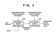
- FIG. 5 is a block diagram showing the internal arrangement of a neighboring region selection/analysis unit which executes neighboring region selection/analysis processing in step S 108 of FIG. 1 .
- the neighboring region selection/analysis unit comprises a neighboring region selection unit 502 and neighboring region analysis unit 504 .
- the neighboring region selection unit 502 receives image information (pixel position and pixel value), position information of an embedding target pixel, and the neighboring region selection method NS.
- the neighboring region selection unit 502 determines a neighboring region on the basis of the pieces of input information.
- the neighboring region may not be fixed in the entire image, but may be changed in accordance with the pixel position or predetermined key information.
- the neighboring region selection unit 502 outputs neighboring region information (pixel position, pixel value, and the like) to the neighboring region analysis unit 504 on the output stage.
- the neighboring region analysis unit 504 receives the neighboring region information (pixel position, pixel value, and the like) and the neighboring region analysis method NA, and analyzes the pixel value of the neighboring region on the basis of the pieces of input information.
- the neighboring region analysis unit 504 outputs a neighboring region analysis value (neighboring region pixel value and neighboring region characteristic value).
- FIG. 6 is a view showing part of an 8-bit grayscale input image 601 and an output image 602 (noise-added image) containing a visible digital watermark.
- Pixels (pixels 13 a , 14 a , 15 a , 18 a , 19 a , and 20 a ) surrounded by thick frames in FIG. 6 falls within the watermark image shape, and are pixels subjected to reversible noise embedding.
- the arithmetic bit region of the pixel 13 a is selected on the basis of a region near the pixel 13 a .
- the neighboring region is determined using the neighboring region selection means 502 .
- the neighboring region selection means 502 in the first embodiment selects a pixel left to a pixel of interest.
- a left adjacent pixel 12 a (pixel value “112”) is selected as a neighboring region. Selection of a plurality of pixel regions as neighboring regions will be described later.
- the pixel 12 a (pixel value “112”) is input to the neighboring region analysis unit 504 .
- the neighboring region analysis means 504 directly outputs the input pixel value “112” as a neighboring region analysis value.
- the arithmetic bit region of the embedding target pixel 13 a is determined on the basis of the neighboring region analysis value obtained by the preceding neighboring region selection/analysis processing.
- the first embodiment determines an arithmetic bit region as follows.
- FIG. 3 is a block diagram showing an arithmetic bit region determination unit which executes arithmetic bit region determination processing in step S 110 .
- An arithmetic bit region determination unit 300 receives a neighboring region analysis value 302 input from neighboring region selection/analysis processing in step S 108 , an initially set visible intensity value S ( 306 ), and an arithmetic bit region determination table T_N 304 .
- the arithmetic bit region determination unit 300 determines the arithmetic bit region of an embedding target pixel on the basis of the neighboring region analysis value 302 , arithmetic bit region determination table T_N 304 , and visible intensity value S 306 , and outputs the arithmetic bit region as arithmetic bit region information 308 .
- the arithmetic bit region determination table T_N is a lookup table used to determine an arithmetic bit region by arithmetic bit region determination processing in step S 110 .
- FIGS. 4A and 4B show examples of the arithmetic bit region determination table T_N which corresponds to the neighboring region analysis value (the pixel value of the pixel in the neighboring region).
- the arithmetic bit region at a pixel of interest shifts to a lower bit.
- reference numeral 401 denotes a neighboring region analysis value ( FIGS. 4A and 4B show only a neighboring region pixel value for descriptive convenience); 402 , an arithmetic bit region of an embedding target pixel that corresponds to the neighboring region analysis value (in FIGS. 4A and 4B , a bit position “Y” is an arithmetic bit region); and 403 , a maximum change amount ⁇ max calculated from the arithmetic bit region. A bit having no “Y” is not changed.
- the neighboring region analysis value in FIGS. 4A and 4B , the neighboring region pixel value calculated from the neighboring region
- the visible intensity value S have values which correspond to the arithmetic bit region.
- the arithmetic bit region determination means 300 selects either arithmetic bit region determination table in accordance with the visible intensity S.
- the arithmetic bit region determination unit 300 looks up the selected arithmetic bit region determination table T_N, and reads and outputs an arithmetic bit region which corresponds to the input neighboring region analysis value 302 and visible intensity value S 306 .
- step S 112 bit calculation is executed between a serial bit sequence as shown in FIG. 2 and the bit of the arithmetic bit region in the arithmetic bit region determined by the above-described method.
- step S 114 the arithmetic result in step S 112 is written in a corresponding arithmetic bit region of an output image.
- the outline of reversible noise removal processing according to the first embodiment will be briefly described with reference to FIG. 7 .
- the apparatus arrangement is substantially the same as that of the apparatus which embeds noise, and a detailed description thereof will be omitted.
- a reversible noise-embedded image W comprised of a plurality of pixels each having a pixel position and pixel value, watermark image shape information M comprised of a pixel position representing the shape of an embedded image, a random number key R for generating a predetermined serial bit sequence expressed by binary numbers, an arithmetic bit region determination table T_N which defines a bit region subjected to arithmetic processing among pixel values, and a visible intensity value S which defines the intensity of a visible digital watermark are input.
- An output image E is so set as to be identical to the input image W (a copy of the input image W is generated and used as the output image E).
- the watermark image shape information M, random number key R, arithmetic bit region determination table T_N, and visible intensity value S are used as key information for removing reversible noise.
- step S 704 an unprocessed pixel of the input image is selected.
- step S 706 whether noise is multiplexed on the selected pixel is determined on the basis of the pixel position in image shape information (position “0” or “1”). If NO in step S 706 , processing for the pixel ends.
- step S 706 processing advances to step S 708 to determine a region (left adjacent pixel in the first embodiment) near the embedding target pixel on the basis of the initially set neighboring region selection method NS.
- the pixel value in the neighboring region is analyzed in accordance with the initially set neighboring analysis method NA, generating a neighboring region analysis value.
- step S 710 an arithmetic bit region to be processed by arithmetic processing in step S 712 is determined on the basis of the neighboring region analysis value generated in step S 708 and the visible intensity value S.
- step S 712 inverse arithmetic processing is performed between the bit of the arithmetic bit region that is determined in step S 710 and a serial bit sequence generated from the random number key R input by initial setting in step S 702 .
- This arithmetic processing is inverse arithmetic processing (decoding processing) corresponding to arithmetic processing in embedding.
- an exclusive-OR is calculated for the arithmetic bit region by using the same serial bit as that used in embedding. As a result, the pixel value can be completely restored to an original pixel value.
- step S 714 write processing of writing, in a corresponding pixel of the output image E, the arithmetic bit region value obtained by processing the bit region value of the input pixel is executed.
- step S 716 whether all pixels have been processed is determined. If NO in step S 716 , processing returns to step S 704 to continue the above-described processing until all pixels have been processed.
- the neighboring region selection method must select a neighboring region so as to refer to the pixel value of a neighboring region used to determine an arithmetic bit region in inverse arithmetic processing (removal of reversible noise).
- a pixel left adjacent to an embedding target pixel is referred to as a neighboring region, and reversible noise is added/removed to/from the pixel of interest.
- the neighboring region must be completely reconstructed to an original image.
- the leftmost vertical line of image shape information is changed to “0”, in other words, is excluded from the noise embedding target.
- the start pixel remains original and satisfactorily functions as a neighboring region in noise removal of each line in the left-to-right direction.
- the start pixel of each line is permitted to be a noise multiplexing target, no neighboring region exists, and the arithmetic bit region is fixed.
- the left adjacent pixel 12 a (pixel value “112”) is selected and analyzed as a neighboring region.
- “112” is output as the neighboring region pixel value of the neighboring region analysis value.
- a pixel value “126” is calculated for the pixel 13 a (pixel value “116”) by arithmetic processing (exclusive-OR) between the bit values in the arithmetic bit region of the pixel 13 a and a serial bit sequence.
- the pixel value “126” is written in the pixel 13 a of the output image 602 .
- the processing target shifts to the pixel 14 a .
- the arithmetic bit region of the pixel 14 a is determined using the arithmetic bit region determination table T_N by referring to the left adjacent pixel 13 a (pixel value “116” before change) of the input image 601 .
- a pixel value “98” is calculated for the pixel 14 a (pixel value “114”) by arithmetic processing between the arithmetic bit region and the serial bit sequence.
- the pixel value “98” is written in the pixel 14 a of the output image 602 .
- the pixel values of left adjacent pixels before change are sequentially read out to embed reversible noise.
- a step of removing reversible noise embedded in the above-described way will be explained.
- pieces of necessary information such as a noise-multiplexed image, visible intensity, image shape information, and random number key have already been input, as described above.
- the left adjacent reconstructed pixel 12 a (pixel value “112”) of the output image 602 is selected and analyzed as a neighboring region. As a result, “112” is output as the neighboring region pixel value of the neighboring region analysis value.
- the arithmetic bit region of the pixel 13 a is determined using the arithmetic bit region determination table T_N (selected by the visible intensity S).
- a restored pixel value “116” is calculated for the pixel 13 a (pixel value “126” after watermark embedding) by arithmetic processing between the bit value of the arithmetic bit region and a serial bit sequence.
- the pixel value “116” is written in the pixel 13 a of the output image 601 (original image).
- the removal target pixel shifts to the pixel 14 a .
- the left adjacent pixel 13 a of the input image 601 but the left adjacent reconstructed pixel 13 a (restored pixel value “116”) in the reconstructed output image 602 is selected and analyzed.
- “116” is output as the neighboring region pixel value of the neighboring region analysis value.
- the arithmetic bit region of the pixel 14 a is determined using the arithmetic bit region determination table T_N.
- a pixel value “114” is calculated for the pixel 14 a (pixel value “98”) by arithmetic processing between the bit value of the arithmetic bit region and the serial bit sequence.
- the pixel value “114” is written in the pixel 14 a of the output image 602 (original image).
- the pixel values of adjacent reconstructed pixels are sequentially selected and analyzed to determine the same arithmetic bit region as that in embedding, completely removing reversible noise.
- a pixel left adjacent to an embedding target pixel is selected as a neighboring region for descriptive convenience.
- a pixel on an immediately preceding line at the same position in the main scanning direction may be selected as a neighboring region.
- a reconstructed pixel is referred to.
- a region of a plurality of pixels may be selected and analyzed as a neighboring region.
- the neighboring region selection unit selects the pixels 7 a , 8 a , and 12 a as a region near the pixel 13 a of interest.
- the neighboring region analysis unit predicts the pixel value of the embedding target pixel 13 a from the pixel values of the pixels 7 a , 8 a , and 12 a , and sets the predicted value as a neighboring region pixel value.
- the neighboring region selection unit may select four left pixels 1 a , 2 a , 6 a , and 7 a as a region near the pixel 13 a .
- the neighboring region analysis means may also calculate a variance, frequency coefficient, and the like in the neighboring region, and set them as neighboring region characteristic values.
- An arithmetic bit region corresponding to the variance, frequency coefficient, and the like is defined in the arithmetic bit region determination table T_N.
- the arithmetic bit region corresponding to an input pixel value “112” as a neighboring region analysis value (neighboring region pixel value) is defined by B 4 , B 3 , and B 1 .
- the reversible noise addition method of the first embodiment can finely set an arithmetic bit region on the basis of a neighboring region pixel value almost equal to the value of an embedding target pixel and a neighboring region analysis value obtained from a neighboring region characteristic value near the embedding target pixel.
- reversible noise may stop, as described above.
- removing reversible noise from the pixel having no neighboring region it is known that no reversible noise is added. Removal of reversible noise need not be executed until the neighboring region is obtained.
- arithmetic bit processing may be done for a fixed arithmetic bit region determined only in accordance with the visible intensity value S.
- inverse arithmetic processing is performed for the arithmetic bit region determined only in accordance with the visible intensity value S, thereby removing reversible noise.
- an arithmetic bit region is determined in accordance with the neighboring region analysis value for the pixel value of an input image which attains the size of a neighboring region determined by the neighboring region selection method NS.
- the human visual characteristic is more sensitive to a change in luminance value at a lower luminance value and less sensitive to a change in luminance value at a higher luminance value.
- the uniform color space is also effective for determining the arithmetic bit region (maximum change amount ⁇ max).
- the first embodiment can set the pixel value change amount such that the noise amount added by arithmetic processing changes in accordance with the image grayscale in a region represented by watermark image shape information of an original image while maintaining the feature of an original image.
- no original image is required for removing added noise.
- Introduction of high-security cryptography to arithmetic processing makes it difficult to remove added noise.
- the arithmetic bit region determination table T_N is used to determine an arithmetic bit region.
- An arithmetic bit region determination function F expressed by a formula can also be used, and this method also falls within the scope of the present invention.
- a server which services images on the Internet is installed. Images containing additional information having undergone processing in FIG. 1 , and pieces of specific information (image shape information M, random number key R, arithmetic bit region determination table T, and visible intensity S) for reconstructing the respective images are stored and managed.
- the user selects and downloads a desired image.
- the downloaded image contains visible additional information (e.g., a photographer name and photographing date and time), as described above, and can satisfactorily present the atmosphere of the entire image.
- the user notifies the server that he/she wants to reconstruct the downloaded image into an original image (e.g., by clicking a corresponding button on a browser or the like).
- the server transmits not the original image itself but pieces of information (image shape information M, random number key R, arithmetic bit region determination table T, and visible intensity value S) which are specific to the image and necessary for reconstruction (this can prevent leakage of the original image).
- these pieces of information are encrypted by a private key, which enhances security.
- the user PC receives these pieces of information, and performs processing of executing processing shown in FIG. 7 .
- the random number key R a common function for generating a random number is held in the server and client, instead of transmitting a random number itself. Only an initial parameter for generating a random number is transmitted. If the same parameter is used for all images, all images held by the server can be undesirably reconstructed. To prevent this, the parameter is changed for each image.
- the first embodiment adopts two tables for determining an arithmetic bit region, as shown in FIGS. 4A and 4B . Three or more tables may also be adopted. B 7 (MSB) and B 6 are excluded from the arithmetic bit region. If the visible intensity is further increased or wanted to be increased, these bits can also be contained in the arithmetic region.
- the visible intensity S may be set freely by the user or automatically.
- the visible intensity S may be automatically determined using the range width and central luminance of the luminance distribution (histogram or the like may be created) of an original image as parameters.
- the arithmetic bit region in which visible noise is embedded is assigned to a relatively low bit region, and additional information by visible noise may be hardly seen.
- the arithmetic bit region is set up to a high bit so as to change the image to a high luminance. Accordingly, the visible intensity can be automatically increased.
- noise addition processing is done for each pixel.
- reversible noise is added to an image compression-coded by JPEG, JPEG 2000, or the like.
- a compression coding method such as JPEG or JPEG 2000 does not define an input color component.
- R Red
- G Green
- B Blue
- Y luminance
- Cb color difference
- Cr color difference
- a frequency conversion coefficient representing the luminance component of a color image compression-coded by JPEG or JPEG 2000 is used as a visible digital watermark embedding component. Such component can be embedded in a luminance value without any special processing.
- JPEG compression coding compression coding is performed for each block.
- a JPEG-compression-coded image has a minimum encoding unit (in general, 8 ⁇ 8 pixels), and basic compression coding processing is done for each unit.
- watermark image shape information is set not for each pixel but for the minimum encoding unit. This facilitates applying the method of the first embodiment.
- DCT transform is performed. If the pixel block is not located at a position where noise should be multiplexed, general JPEG encoding is done. If the pixel block is determined to be located at the multiplexing position, the same processing as that in the first embodiment is executed for bits which constitute a DC component value obtained as a result of DCT transform. At this time, the visible intensity value S is referred to, similar to the first embodiment. As a neighboring region, a DC component after orthogonal transform of a neighboring pixel block is used.
- reference numeral 801 denotes an image block in the minimum encoding unit in JPEG compression coding.
- DCT Discrete Cosine Transform
- Reference numeral 802 denotes a DC component (average value) of a DCT coefficient obtained for the minimum encoding unit after DCT transform. The remaining 63 coefficients are AC coefficients.
- the average value in the minimum encoding unit ( 801 ) can be changed by performing arithmetic bit region calculation processing described in the first embodiment for the DC component of the DC coefficient in the minimum encoding unit. Reversible noise can be added to each block.
- watermark image shape information is information which designates the minimum encoding unit block subjected to embedding
- image shape information M can be reduced.
- JPEG whether to perform multiplexing for the 8 ⁇ 8 pixel unit is determined.
- One pixel of image shape information corresponds to 8 ⁇ 8 pixels of an original image (the capacity is reduced to 1/64).
- a block to be processed undergoes noise embedding is determined on the basis of image shape information before inverse DCT transform. If the pixel is determined not to be subjected to noise embedding, the block is decoded by general processing. If the pixel is determined to be subjected to noise embedding, an arithmetic bit region at a DC component is obtained (specified) by looking up an arithmetic bit region determination table T determined by the visible intensity value S. An arithmetic bit region is determined from the restored DC component of a neighboring region by looking up the table. Logical calculation (exclusive-OR calculation according to the first embodiment) with a serial bit sequence generated by a random number is performed to reconstruct the image.
- JPEG compression coding data is discarded by quantization processing, and the image cannot be completely reconstructed into an original image.
- at least an image from which noise is removed to almost an original image can be obtained at the same quality as a decoding result by general JPEG.
- DCT coefficients in a plurality of neighboring minimum encoding unit blocks or another DCT coefficient in the minimum encoding unit serving as an embedding target block may be used.
- An AC coefficient as an AC component in the minimum encoding unit serving as an embedding target block represents the frequency characteristic of the embedding target block, and can be effectively adopted as the neighboring region analysis value (neighboring region characteristic value).
- a JPEG 2000-compression-coded image is compression-coded by dividing the image stepwise by the band from a low frequency to a high frequency by using DWT (Discrete Wavelet Transform) while holding image shape information.
- DWT Discrete Wavelet Transform
- FIG. 9 is a view showing band division by discrete wavelet transform in JPEG 2000 compression coding.
- LL is a low-frequency-component subblock as a result of performing DWT twice. All pixels which constitute the subblock LL undergo the same embedding as that in the first embodiment.
- the neighboring region to be referred to may be the subblock LL of an adjacent pixel block.
- the DWT coefficients of other subblocks (subbands) HL 2 , LH 2 , HH 2 , HL 1 , LH 1 , and HH 1 which constitute a tree structure together with LL in the block of interest may be used as neighboring regions.
- Information on the frequency characteristic of an embedding target section in an original image can be obtained from the DWT coefficients of subbands.
- the DWT coefficients of subbands are effective as a neighboring region characteristic value which determines a visible digital watermark intensity.
- an arithmetic bit region determination table must be designed in consideration of the fact that the DWT coefficient takes a positive or negative value.
- a 1-bit bit plane having the same size as the image size is prepared for ROI (Region Of Interest).
- ROI Region Of Interest
- the watermark image shape information When watermark image shape information is to be presented like a visible digital watermark to the image appreciator in the absence of any ROI, the watermark image shape information may be set in ROI.
- visible logotype information representing copyright information is described in ROI.
- the logotype information can be first presented to the appreciator, explicitly presenting the copyright holder of the content to the user.
- Watermark image shape information has been encoded together with an image as ROI information. Key information necessary to remove reversible noise can be reduced.
- Watermark image shape information necessary to remove reversible noise can also be attached to a predetermined position such as the header of an image file. Reconstruction of a noise-added image into an original image requires only necessary key information in addition to the image file, reducing the delivered information amount.
- a key (and watermark image shape information) necessary to remove reversible noise has a relatively small information amount, and can be attached to a predetermined position such as the header of an image file.
- the key (and watermark image shape information) may be encrypted by predetermined cryptography (e.g., public key cryptography), and attached to a predetermined position such as the header of an image file.
- the first embodiment has described only an exclusive-OR (XOR calculation) as cryptography.
- the present invention can also adopt secret key cryptography such as DES or public key cryptography by collecting a plurality of arithmetic bit regions into a predetermined processing unit (e.g., 64 bits).
- a neighboring region must have been reconstructed in removing reversible noise from an embedding target pixel.
- a region left adjacent to the embedding target pixel is set as a neighboring region, a predetermined number of bits must be collected from the arithmetic bit regions of a plurality of pixels in the vertical direction and encrypted.
- cryptography belonging to stream cryptography capable of processing for one to several bits may be employed.
- the second embodiment has exemplified DES as cryptography, but may adopt another secret key cryptography such as AES, FEAL, IDEA, RC2, RC4, RC5, MISTY, Caesar cryptography, Viginere cryptography, Beaufort cryptography, Playfair cryptography, Hill cryptography, or Vernam cryptography.
- the second embodiment has exemplified a still image, but the same principle can also be applied to a moving image.
- reversible noise can be relatively easily embedded using an intermediate frame as an embedding target.
- Motion JPEG 2000 reversible noise can be repetitively embedded by the same method as that of JPEG 2000 compression coding in the time frame direction.
- addition of reversible noise to a moving image also falls within the scope of the present invention.
- the present invention has mainly described addition of reversible noise corresponding to the pixel value of an image.
- a visible digital watermark can also be embedded by adding strong noise to watermark image shape information. Embedding of a visible digital watermark using the above-described method of the present invention also falls within the scope of the present invention.
- An OS or the like running on the computer performs part or all of processing.
- program codes read out from the storage medium are written in the memory of a function expansion board inserted into the computer or the memory of a function expansion unit connected to the computer, and the CPU of the function expansion board or function expansion unit performs part or all of actual processing on the basis of the instructions of the program codes.
- functions equal to those of the embodiments can be realized, the same effects can be obtained, and the objects of the present invention can be achieved.
- an input image and key are input, and some of the building values of the building elements of the input image are referred to for the building values of the building elements of the input image.
- Calculation based on the key is executed to change the building values.
- Reversible noise can be embedded in an original image with high security in accordance with the feature of the input image, satisfactorily protecting copyrights.
- the reversible noise-embedded image and key are input, and calculation reverse to the above calculation is executed. As a result, the reversible noise can be removed to reconstruct the original image.
- noise can be multiplexed on the image data to reversibly embed visible additional information with a noise-multiplexed distribution.
Landscapes
- Physics & Mathematics (AREA)
- General Physics & Mathematics (AREA)
- Engineering & Computer Science (AREA)
- Theoretical Computer Science (AREA)
- Editing Of Facsimile Originals (AREA)
- Image Processing (AREA)
- Television Signal Processing For Recording (AREA)
- Television Systems (AREA)
- Compression Or Coding Systems Of Tv Signals (AREA)
Applications Claiming Priority (2)
| Application Number | Priority Date | Filing Date | Title |
|---|---|---|---|
| JP2002191132A JP4054619B2 (ja) | 2002-06-28 | 2002-06-28 | 画像処理装置及び方法、並びにコンピュータプログラム及びコンピュータ可読記憶媒体 |
| JP2002-191132 | 2002-06-28 |
Publications (2)
| Publication Number | Publication Date |
|---|---|
| US20040001609A1 US20040001609A1 (en) | 2004-01-01 |
| US7269272B2 true US7269272B2 (en) | 2007-09-11 |
Family
ID=29774358
Family Applications (1)
| Application Number | Title | Priority Date | Filing Date |
|---|---|---|---|
| US10/600,532 Expired - Fee Related US7269272B2 (en) | 2002-06-28 | 2003-06-23 | Image processing apparatus for embedding information with a noise-multiplexed distribution, and method, computer program, and computer-readable storage medium therefor |
Country Status (2)
| Country | Link |
|---|---|
| US (1) | US7269272B2 (enExample) |
| JP (1) | JP4054619B2 (enExample) |
Cited By (1)
| Publication number | Priority date | Publication date | Assignee | Title |
|---|---|---|---|---|
| US20050165782A1 (en) * | 2003-12-02 | 2005-07-28 | Sony Corporation | Information processing apparatus, information processing method, program for implementing information processing method, information processing system, and method for information processing system |
Families Citing this family (6)
| Publication number | Priority date | Publication date | Assignee | Title |
|---|---|---|---|---|
| JP2004282677A (ja) * | 2003-01-21 | 2004-10-07 | Canon Inc | 画像処理方法 |
| US8049933B2 (en) * | 2003-09-17 | 2011-11-01 | Canon Kabushiki Kaisha | Copy-forgery-inhibited pattern image generation method and image processing apparatus |
| US20050058476A1 (en) | 2003-09-17 | 2005-03-17 | Canon Kabushiki Kaisha | Copy-forgery-inhibited pattern density parameter determination method, copy-forgery-inhibited pattern image generation method, and image processing apparatus |
| KR100643230B1 (ko) * | 2004-08-30 | 2006-11-10 | 삼성전자주식회사 | 디스플레이장치의 제어방법 |
| JP4653694B2 (ja) * | 2006-05-15 | 2011-03-16 | 株式会社エクシング | コンテンツ配信サーバ装置及びコンテンツ配信方法等 |
| CN111010490A (zh) * | 2019-12-12 | 2020-04-14 | 上海众源网络有限公司 | 水印添加方法、装置、电子设备及计算机可读存储介质 |
Citations (14)
| Publication number | Priority date | Publication date | Assignee | Title |
|---|---|---|---|---|
| JPH05110971A (ja) | 1991-01-24 | 1993-04-30 | Toshiba Corp | 画像作成装置 |
| US5530759A (en) * | 1995-02-01 | 1996-06-25 | International Business Machines Corporation | Color correct digital watermarking of images |
| JPH08256321A (ja) | 1995-01-17 | 1996-10-01 | Nippon Telegr & Teleph Corp <Ntt> | 画像データ変換装置およびその逆変換装置 |
| JP2000184173A (ja) | 1998-12-11 | 2000-06-30 | Canon Inc | 画像処理方法、装置、画像配付方法、システム及びコンピュータ読み取り可能な記憶媒体 |
| US6137892A (en) * | 1992-07-31 | 2000-10-24 | Digimarc Corporation | Data hiding based on neighborhood attributes |
| US6233347B1 (en) | 1998-05-21 | 2001-05-15 | Massachusetts Institute Of Technology | System method, and product for information embedding using an ensemble of non-intersecting embedding generators |
| US20010017709A1 (en) | 2000-01-31 | 2001-08-30 | Tomochika Murakami | Image processing apparatus and method, and storage medium |
| US20020002679A1 (en) | 2000-04-07 | 2002-01-03 | Tomochika Murakami | Image processor and image processing method |
| US20030099373A1 (en) * | 2001-11-27 | 2003-05-29 | Sanghyun Joo | Robust blind watermarking method in wavelet DC components |
| US6738493B1 (en) | 1998-06-24 | 2004-05-18 | Nec Laboratories America, Inc. | Robust digital watermarking |
| US6975746B2 (en) | 1993-11-18 | 2005-12-13 | Digimarc Corporation | Integrating digital watermarks in multimedia content |
| US6996248B2 (en) | 2001-06-13 | 2006-02-07 | Qualcomm, Incorporated | Apparatus and method for watermarking a digital image |
| US20060115112A1 (en) * | 2000-03-31 | 2006-06-01 | Intel Corporation | System and method for marking data and document distribution |
| US7174030B2 (en) * | 2001-02-06 | 2007-02-06 | Victor Company Of Japan, Ltd. | Method and apparatus for embedding and reproducing watermark into and from contents data |
-
2002
- 2002-06-28 JP JP2002191132A patent/JP4054619B2/ja not_active Expired - Fee Related
-
2003
- 2003-06-23 US US10/600,532 patent/US7269272B2/en not_active Expired - Fee Related
Patent Citations (16)
| Publication number | Priority date | Publication date | Assignee | Title |
|---|---|---|---|---|
| JPH05110971A (ja) | 1991-01-24 | 1993-04-30 | Toshiba Corp | 画像作成装置 |
| US6137892A (en) * | 1992-07-31 | 2000-10-24 | Digimarc Corporation | Data hiding based on neighborhood attributes |
| US6975746B2 (en) | 1993-11-18 | 2005-12-13 | Digimarc Corporation | Integrating digital watermarks in multimedia content |
| JPH08256321A (ja) | 1995-01-17 | 1996-10-01 | Nippon Telegr & Teleph Corp <Ntt> | 画像データ変換装置およびその逆変換装置 |
| JPH08241403A (ja) | 1995-02-01 | 1996-09-17 | Internatl Business Mach Corp <Ibm> | 画像の色変化のないディジタル・ウォーターマーキング |
| EP0725529A2 (en) | 1995-02-01 | 1996-08-07 | International Business Machines Corporation | Color correct digital watermarking of images |
| US5530759A (en) * | 1995-02-01 | 1996-06-25 | International Business Machines Corporation | Color correct digital watermarking of images |
| US6233347B1 (en) | 1998-05-21 | 2001-05-15 | Massachusetts Institute Of Technology | System method, and product for information embedding using an ensemble of non-intersecting embedding generators |
| US6738493B1 (en) | 1998-06-24 | 2004-05-18 | Nec Laboratories America, Inc. | Robust digital watermarking |
| JP2000184173A (ja) | 1998-12-11 | 2000-06-30 | Canon Inc | 画像処理方法、装置、画像配付方法、システム及びコンピュータ読み取り可能な記憶媒体 |
| US20010017709A1 (en) | 2000-01-31 | 2001-08-30 | Tomochika Murakami | Image processing apparatus and method, and storage medium |
| US20060115112A1 (en) * | 2000-03-31 | 2006-06-01 | Intel Corporation | System and method for marking data and document distribution |
| US20020002679A1 (en) | 2000-04-07 | 2002-01-03 | Tomochika Murakami | Image processor and image processing method |
| US7174030B2 (en) * | 2001-02-06 | 2007-02-06 | Victor Company Of Japan, Ltd. | Method and apparatus for embedding and reproducing watermark into and from contents data |
| US6996248B2 (en) | 2001-06-13 | 2006-02-07 | Qualcomm, Incorporated | Apparatus and method for watermarking a digital image |
| US20030099373A1 (en) * | 2001-11-27 | 2003-05-29 | Sanghyun Joo | Robust blind watermarking method in wavelet DC components |
Non-Patent Citations (6)
| Title |
|---|
| H. Daren, L. Jiufen, H. Jiwu, and L. Hongmei, "A DWT-Based Image Watermarking Algorithm," Proceedings of the IEEE International Conference on Multimedia and Expo, pp. 429-432, 2001. * |
| J.Huang, Y. Q.Shi, and Y.Shi, "Embedding image watermarks in DC components," IEEE Trans. Circuits Syst. Video Technol., vol. 10, pp. 974-979, Sep. 2000. * |
| S. D. Lin and C.-F. Chen, "A Robust DCT-Based Watermarking for Copyright Protection," IEEE Transactions on Consumer Electronics, 46(3), Aug. 2000, pp. 415-421. * |
| S. P. Mohanty, K. R. Ramakrishnan, and M. S. Kankanhalli, "A DCT domain watermarking technique for images," in Proc. IEEE Int. Conf. Multimedia Expo, 2000, pp. 1029-1032. * |
| Y. Hu and S. Kwong, "Wavelet domain adaptive visible watermarking," Electron. Lett., vol. 37, Sep. 2001. * |
| Y. K. Lee and L. H. Chen, "High capacity image steganographic model," Proc: Inst. Elect. Eng., Vis. Image Signal Processing, vol. 147, No. 3, pp. 288-294, 2000. * |
Cited By (2)
| Publication number | Priority date | Publication date | Assignee | Title |
|---|---|---|---|---|
| US20050165782A1 (en) * | 2003-12-02 | 2005-07-28 | Sony Corporation | Information processing apparatus, information processing method, program for implementing information processing method, information processing system, and method for information processing system |
| US7487151B2 (en) * | 2003-12-02 | 2009-02-03 | Sony Corporation | Information processing apparatus, information processing method, program for implementing information processing method, information processing system, and method for information processing system |
Also Published As
| Publication number | Publication date |
|---|---|
| JP2004040236A (ja) | 2004-02-05 |
| JP4054619B2 (ja) | 2008-02-27 |
| US20040001609A1 (en) | 2004-01-01 |
Similar Documents
| Publication | Publication Date | Title |
|---|---|---|
| US7197162B2 (en) | Image processing apparatus and method, computer program, and computer-readable storage medium | |
| US7200242B2 (en) | Image processing apparatus and method, computer program, and computer-readable storage medium | |
| Kutter et al. | Digital signature of color images using amplitude modulation | |
| Busch et al. | Digital watermarking: From concepts to real-time video applications | |
| JP3960597B2 (ja) | 符号生成装置、画像処理装置、符号生成プログラム、画像処理プログラムおよび記憶媒体 | |
| US6823455B1 (en) | Method for robust watermarking of content | |
| Yang et al. | A contrast-sensitive reversible visible image watermarking technique | |
| US6064764A (en) | Fragile watermarks for detecting tampering in images | |
| Pereira et al. | Optimal transform domain watermark embedding via linear programming | |
| US8238435B2 (en) | Modifying bitstreams | |
| JP3982686B2 (ja) | 符号生成装置、符号生成プログラム、および記憶媒体 | |
| US20040208339A1 (en) | Image processing apparatus, program, and storage medium that can selectively vary embedding specification of digital watermark data | |
| US7269273B2 (en) | Image processing apparatus for embedding information with a noise-multiplexed distribution, and method, computer program, and computer-readable storage medium therefor | |
| Cheddad et al. | Enhancing steganography in digital images | |
| US7269272B2 (en) | Image processing apparatus for embedding information with a noise-multiplexed distribution, and method, computer program, and computer-readable storage medium therefor | |
| US7606426B1 (en) | Image processing apparatus and method and storage medium | |
| Tsai et al. | Highly imperceptible video watermarking with the Watson's DCT-based visual model | |
| JP4118776B2 (ja) | 電子透かし埋め込み方法及び抽出方法、ならびに電子透かし装置 | |
| Negrat et al. | Variable length encoding in multiple frequency domain steganography | |
| Verma et al. | Robust color image watermarking scheme using JFIF-YCbCr color space in wavelet domain | |
| Genov | Digital watermarking of bitmap images | |
| Kothari et al. | Video watermarking in spatial domain | |
| Vural et al. | Robust digital cinema watermarking | |
| Jimson | Removable Visible Watermarking Using Discrete Fourier Transform | |
| JP2001257598A (ja) | 符号化装置及び復号化装置 |
Legal Events
| Date | Code | Title | Description |
|---|---|---|---|
| AS | Assignment |
Owner name: CANON KABUSHIKI KAISHA, JAPAN Free format text: ASSIGNMENT OF ASSIGNORS INTEREST;ASSIGNOR:MURAKAMI, TOMOCHIKA;REEL/FRAME:014225/0639 Effective date: 20030613 |
|
| STCF | Information on status: patent grant |
Free format text: PATENTED CASE |
|
| FPAY | Fee payment |
Year of fee payment: 4 |
|
| FPAY | Fee payment |
Year of fee payment: 8 |
|
| FEPP | Fee payment procedure |
Free format text: MAINTENANCE FEE REMINDER MAILED (ORIGINAL EVENT CODE: REM.); ENTITY STATUS OF PATENT OWNER: LARGE ENTITY |
|
| LAPS | Lapse for failure to pay maintenance fees |
Free format text: PATENT EXPIRED FOR FAILURE TO PAY MAINTENANCE FEES (ORIGINAL EVENT CODE: EXP.); ENTITY STATUS OF PATENT OWNER: LARGE ENTITY |
|
| STCH | Information on status: patent discontinuation |
Free format text: PATENT EXPIRED DUE TO NONPAYMENT OF MAINTENANCE FEES UNDER 37 CFR 1.362 |
|
| FP | Lapsed due to failure to pay maintenance fee |
Effective date: 20190911 |