US7254994B2 - Device for detecting and signaling a physical value when connected to a rim, and rim comprising such a device - Google Patents
Device for detecting and signaling a physical value when connected to a rim, and rim comprising such a device Download PDFInfo
- Publication number
- US7254994B2 US7254994B2 US10/818,551 US81855104A US7254994B2 US 7254994 B2 US7254994 B2 US 7254994B2 US 81855104 A US81855104 A US 81855104A US 7254994 B2 US7254994 B2 US 7254994B2
- Authority
- US
- United States
- Prior art keywords
- rim
- oscillating circuit
- proximity sensor
- discover
- detecting
- Prior art date
- Legal status (The legal status is an assumption and is not a legal conclusion. Google has not performed a legal analysis and makes no representation as to the accuracy of the status listed.)
- Expired - Lifetime
Links
- 230000011664 signaling Effects 0.000 title claims abstract description 15
- 239000003990 capacitor Substances 0.000 claims description 25
- 229910052751 metal Inorganic materials 0.000 claims description 5
- 239000002184 metal Substances 0.000 claims description 5
- 230000008878 coupling Effects 0.000 claims description 3
- 238000010168 coupling process Methods 0.000 claims description 3
- 238000005859 coupling reaction Methods 0.000 claims description 3
- 239000013589 supplement Substances 0.000 claims 2
- 230000001133 acceleration Effects 0.000 description 14
- DOSMHBDKKKMIEF-UHFFFAOYSA-N 2-[3-(diethylamino)-6-diethylazaniumylidenexanthen-9-yl]-5-[3-[3-[4-(1-methylindol-3-yl)-2,5-dioxopyrrol-3-yl]indol-1-yl]propylsulfamoyl]benzenesulfonate Chemical compound C1=CC(=[N+](CC)CC)C=C2OC3=CC(N(CC)CC)=CC=C3C(C=3C(=CC(=CC=3)S(=O)(=O)NCCCN3C4=CC=CC=C4C(C=4C(NC(=O)C=4C=4C5=CC=CC=C5N(C)C=4)=O)=C3)S([O-])(=O)=O)=C21 DOSMHBDKKKMIEF-UHFFFAOYSA-N 0.000 description 13
- 238000011156 evaluation Methods 0.000 description 8
- 230000008901 benefit Effects 0.000 description 4
- 238000005259 measurement Methods 0.000 description 4
- 238000012544 monitoring process Methods 0.000 description 4
- 230000010355 oscillation Effects 0.000 description 4
- 230000001939 inductive effect Effects 0.000 description 3
- 239000000853 adhesive Substances 0.000 description 2
- 230000001070 adhesive effect Effects 0.000 description 2
- 230000008859 change Effects 0.000 description 2
- 238000013016 damping Methods 0.000 description 2
- 238000013461 design Methods 0.000 description 2
- 238000010586 diagram Methods 0.000 description 2
- 230000005284 excitation Effects 0.000 description 2
- 238000000034 method Methods 0.000 description 2
- 230000008569 process Effects 0.000 description 2
- 229910000831 Steel Inorganic materials 0.000 description 1
- 230000003213 activating effect Effects 0.000 description 1
- 239000004411 aluminium Substances 0.000 description 1
- 229910052782 aluminium Inorganic materials 0.000 description 1
- XAGFODPZIPBFFR-UHFFFAOYSA-N aluminium Chemical compound [Al] XAGFODPZIPBFFR-UHFFFAOYSA-N 0.000 description 1
- 238000009529 body temperature measurement Methods 0.000 description 1
- 238000010276 construction Methods 0.000 description 1
- 230000001419 dependent effect Effects 0.000 description 1
- 238000011161 development Methods 0.000 description 1
- 230000018109 developmental process Effects 0.000 description 1
- 230000004069 differentiation Effects 0.000 description 1
- 230000000694 effects Effects 0.000 description 1
- 230000002349 favourable effect Effects 0.000 description 1
- 230000004044 response Effects 0.000 description 1
- 230000000717 retained effect Effects 0.000 description 1
- 238000005070 sampling Methods 0.000 description 1
- 239000010959 steel Substances 0.000 description 1
- 230000001960 triggered effect Effects 0.000 description 1
Images


Classifications
-
- B—PERFORMING OPERATIONS; TRANSPORTING
- B60—VEHICLES IN GENERAL
- B60C—VEHICLE TYRES; TYRE INFLATION; TYRE CHANGING; CONNECTING VALVES TO INFLATABLE ELASTIC BODIES IN GENERAL; DEVICES OR ARRANGEMENTS RELATED TO TYRES
- B60C23/00—Devices for measuring, signalling, controlling, or distributing tyre pressure or temperature, specially adapted for mounting on vehicles; Arrangement of tyre inflating devices on vehicles, e.g. of pumps or of tanks; Tyre cooling arrangements
- B60C23/02—Signalling devices actuated by tyre pressure
- B60C23/04—Signalling devices actuated by tyre pressure mounted on the wheel or tyre
- B60C23/0408—Signalling devices actuated by tyre pressure mounted on the wheel or tyre transmitting the signals by non-mechanical means from the wheel or tyre to a vehicle body mounted receiver
Definitions
- the invention relates to a device for detecting signaling a physical value of a rim.
- a device of that kind has been known from WO 03/011617 A1.
- the device described in that publication especially serves for determining and signaling an acceleration encountered at the device, the air pressure and/or the temperature prevailing in a pneumatic tire mounted on the rim.
- Such a device which will be described hereafter also as wheel sensor, usually determines the air pressure, acceleration values and/or the temperature at predetermined time intervals, and transmits them at predetermined time intervals equal or greater than the time intervals between the measurements, or else immediately when given threshold values are exceeded, to a receiver and evaluation unit in a vehicle equipped with wheels that are provided with such a wheel sensor.
- the wheel sensor being covered by the pneumatic tire, it is not visible from the outside.
- a bonding connection may be sufficiently reliable and durable under driving conditions. Still, it makes sense to consider means and ways of knowing when a wheel sensor should get detached from the rim for one reason or other. If that should happen, the sensor would be flung against the tire inside, by the centrifugal force produced by the driving motion, and would stay there as long as the vehicle continues to move rapidly, or if it reduces its speed, would roll about in an uncontrolled fashion inside the tire, which could damage or destroy the wheel sensor and/or the tire if this condition should persist for some time.
- WO 03/011616 A1 therefore suggests to investigate at regular intervals the physical values anyway measured by the wheel sensor, namely the acceleration values encountered at the wheel sensor and/or the temperature, in order to determine if the values so measured contain some information suggesting that the wheel sensor may have got detached from the rim.
- WO 03/011617 A1 suggests to observe the temperature because that value is clearly position-dependent.
- WO 03/011617 proposes to observe the acceleration occurring at the wheel sensor because that value may vary atypically when the wheel sensor gets detached from the rim.
- a device according to the invention hereinafter also described as wheel sensor—comprises a proximity sensor which is responsive to the rim. This provides considerable advantages.
- a proximity sensor which directly contacts the rim in a given mounting position of the wheel sensor
- a proximity sensor that responds to the rim in non-contact fashion provides a more reliable and cheaper solution.
- the proximity sensor is not operated continuously; instead, there is provided a timing circuit for activating the proximity sensor at predetermined time intervals, because in this case current consumption is limited and, if the current supply is provided by a battery, long service life can be achieved without battery change.
- the proximity sensor is activated simultaneously with one of the other sensors comprised in the device, especially simultaneously with a pressure sensor intended to measure air pressure in the tire. This guarantees that not only the tire pressure but also the position of the wheel sensor is checked at the time intervals that have been set in advance as a function of the particular safety requirements.
- the air pressure, temperature, acceleration values so determined and the signal of the proximity sensor can then be transmitted in current-saving fashion by a common data telegram.
- a capacitive proximity sensor can be formed by designing and arranging a first capacitor electrode in the wheel sensor in such a way that in the predetermined mounting position of the wheel sensor it will come to lie closely opposite the rim surface so that the rim acts as a second capacitor electrode which, together with the first capacitor electrode, forms a capacitor whose capacitance would vary strongly if the wheel sensor should drop off the rim.
- the proximity sensor comprises two capacitors each of them having a first electrode in the wheel sensor and both of them using the rim as a common coupling electrode. This embodiment provides the advantage that well-defined electric potentials are encountered on the electrodes of the proximity sensor capacitors even without any direct electric connection between the wheel sensor and the rim.
- the proximity sensor is an inductive sensor
- an inductor for example an electric coil
- the predetermined mounting position of the wheel sensor is located especially close to the rim surface. This has the effect that, with the wheel sensor in its predetermined mounting position, the inductive resistance of the coil is clearly higher than in cases where the wheel sensor has got detached from the rim and is more remote from the rim base.
- the proximity sensor comprises an electric oscillating circuit responsive to the rim.
- an oscillating circuit can be designed and used with advantage in different ways, by arranging either one or more capacitors provided in the oscillating circuit or one or more coils provided in the oscillating circuit, or both, in the wheel sensor in such a way that they come to lie especially close to the rim surface in the predetermined mounting position of the wheel sensor so that the rim surface has a clearly measurable influence on the capacitance, the inductivity or both values and, thus, on the behavior of the oscillating circuit.
- the natural frequency of the oscillating circuit of a wheel sensor which still occupies its predetermined mounting position, is shifted toward clearly lower frequencies due to the proximity of the rim to a coil, and the amplitude. of the oscillations is clearly dampened or even fully suppressed. If instead of a coil a capacitor of the oscillating circuit is influenced by the proximity of the rim, then the frequency of the oscillating circuit is likewise shifted toward lower frequencies when the wheel sensor occupies its predetermined mounting position, whereas the capacitive resistance increases when the wheel sensor has got detached from the rim.
- a detector circuit for example one which supplies a voltage signal the value of which provides a measure of the oscillating amplitude, its damping, frequency or frequency variation, depending on the particular design and arrangement of the oscillating circuit.
- Another possibility consists in checking if a response signal is provided and, if so, with which delay it is provided, after short-time excitation of the oscillating circuit.
- Known wheel sensors comprise a microprocessor or ASIC.
- the system clock pulse of the latter can be used with advantage for monitoring the frequency of the oscillating circuit because any frequency measurement can be referred back to a time measurement. So, no additional apparatus input for frequency measurement is required in this case.
- a detector circuit comprising a low-pass filter, a high-pass filter or a band-pass filter whose cut-off frequencies are selected so that differentiation is possible between the two states “wheel sensor position O.K.” and “wheel sensor detached” due to the fact that an oscillation excited in the oscillating circuit is permitted to pass in one of the two conditions whereas it is not in the other one of the two conditions.
- An advantageous possibility to detect relevant variations in the behavior of the oscillating circuit consists in providing an additional capacitor fed by the oscillating circuit, and further to provide a threshold-value detector that monitors the charging condition of such additional capacitor, the threshold-value detector being intended to provide a signal when the charging condition of the capacitor exceeds a given threshold value.
- the oscillating circuit When the oscillating circuit is heavily dampened by the proximity of the rim, it may present a low-ohmic charging path for the additional capacitor so that the latter may cause the threshold-value detector to respond.
- the oscillating circuit becomes a high-ohmic charging path for the additional capacitor so that the latter can no longer be charged up to the predetermined threshold value. In order to obtain clear results, it is necessary in this case that the additional capacitor be reset before every measuring process.
- FIG. 1 shows a radial section through a vehicle wheel with pneumatic tires, having a rim and a wheel sensor connected with the rim base,
- FIG. 2 shows an oblique view of the housing of a device according to the invention, illustrating the position of a circuit board:
- FIG. 3 shows a block diagram of a device according to the invention in combination with a rim
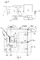
- FIG. 4 shows an example of a circuit of a device according to the invention.
- FIG. 1 shows a wheel having a rim 1 made from metal, especially from steel or aluminium.
- a pneumatic tire 2 is mounted on the rim 1 .
- a wheel sensor 3 arranged below the pneumatic tire 2 , is mounted on the rim base 4 , for example by bonding.
- the wheel sensor 3 mainly serves for monitoring air pressure in the tire 2 and comprises for this purpose a pressure sensor, preferably also a temperature sensor and an acceleration sensor, further a control circuit equipped with a microprocessor or an ASIC, and means for signaling the values so measured by means of a radio transmitter and an antenna.
- the measured values obtained are digitally encoded, supplemented by an identification code defining the particular wheel sensor 3 , and are transmitted by radio via a data bus to a receiver and evaluation unit arranged in the vehicle.
- the energy for the wheel sensor 3 is conveniently supplied by a battery 10 —see FIGS. 3 and 4 —but could be injected as well from the outside, by a sampling transmitter (transponder).
- the wheel sensor comprises an oscillator 5 and, as part of the oscillator, an oscillating circuit 6 which, in the predetermined mounting position of the wheel sensor 3 illustrated in FIG. 1 , is located directly adjacent the rim 1 , which latter influences the oscillating circuit 6 and is, therefore, likewise illustrated as a block in FIG. 2 .
- a detector circuit 16 which has its input connected to the output of the oscillator 5 .
- the wheel sensor 3 comprises an integrated circuit 7 , especially an ASIC or microprocessor.
- the output signal of the detector circuit 16 is supplied to one of the inputs of the integrated circuit 7 and is analyzed and evaluated in the integrated circuit 7 according to predetermined criteria in order to determine if the detector output signal indicates that the wheel sensor 3 occupies its predetermined position at the rim 1 or if it has got detached from the rim 1 .
- the integrated circuit 7 further controls a radio transmitter 8 with an antenna 9 so that it transmits the result of the evaluation of the detector output signal to the receiver and evaluation unit arranged in the vehicle. If the detector output signal indicates that the wheel sensor 3 has got detached from the rim 1 , radio transmitter 8 is immediately activated and caused to transmit that message to the receiver and evaluation unit. Otherwise, it will be sufficient to transmit an O.K. signal to the receiver and evaluation unit occasionally in order to inform the unit that the device according to the invention for monitoring the position of the wheel sensor on the rim 1 is still working.
- the integrated circuit 7 further monitors the other existing wheel sensors 3 , for example, the sensors for pressure, temperature, acceleration and, if necessary, for other physical values, evaluates the values obtained, if necessary, and causes them to be transmitted to the central receiver and evaluation unit provided in the vehicle.
- a battery 10 is provided for supplying the components of the wheel sensor with current.
- the integrated circuit 7 determines a clock frequency at which the oscillator is excited momentarily. Whether or not an oscillation is then encountered, and the frequency, amplitude and damping of such oscillation, then depend on the particular location of the oscillating circuit 6 , i.e. whether or not it occupies a position, in its predetermined mounting position, near the rim 1 within its range of influence. This is to be detected by a detector circuit 16 whose output signal is evaluated by the integrated circuit 7 . In order to ensure that in the predetermined mounting position of the wheel sensor 3 , as illustrated for example in FIG.
- the influence of the rim 1 on the oscillating circuit 6 is as great as possible, the oscillating circuit 6 or at least one of its components having a decisive influence on its behavior (a capacitance or inductance) should be arranged as close to the rim surface 1 as possible.
- This can be achieved by providing the frequency-determining components on the bottom surface of a circuit board 11 , which latter is mounted in the housing 12 of the wheel sensor 3 as close as possible to the bottom surface 13 of the housing and which may exhibit a corresponding concave curvature matching the curvature of the rim base 4 .
- the zone 14 on the circuit board 11 which includes the frequency-determining component of the circuit 6 , which is to be influenced by the rim 1 , should be arranged most conveniently at that point where the smallest distance exists between the circuit board 11 and the bottom surface 13 of the housing, as illustrated in FIG. 3 .
- FIG. 4 shows part of an embodiment of the circuit illustrated in FIG. 2 , but in greater detail.
- the oscillator 5 is designed as a Colpitts oscillator. This is a transistor oscillator with an emitter oscillating circuit which distinguishes itself by a particularly simple structure. It comprises an oscillating circuit 6 with an inductivity L 1 and two capacitors C 1 and C 2 fed via a transistor 15 connected as common emitter. The base of the transistor 15 is driven by the integrated circuit 7 via a voltage divider comprising the resistors R 1 and R 2 . A resistor R 3 is connected between the emitter of the transistor 15 and ground. The inductivity of the coil L 1 is influenced by the rim 1 located near the coil.
- the output of the oscillator 5 is connected to the input of the detector circuit 16 .
- the output signal of the oscillator 5 feeds, via a coil L 2 and a resistor R 6 , a capacitor C 3 whose voltage is sampled between R 6 and C 3 and supplied, via a resistor R 5 , to a connection 7 a of the integrated circuit 7 where a switching operating can be triggered by the voltage when it reaches a predetermined value.
- the oscillating circuit With the wheel sensor 3 in its predetermined mounting position, the oscillating circuit is 6 substantially dampened by the rim 1 so that it will oscillate either not at all or at a relatively low frequency when excited by the integrated circuit 7 via its connection 7 b .
- the integrated circuit 7 activates the radio transmitter 8 and causes it to emit a warning signal. Simultaneously with the excitation of the oscillating circuit 6 the integrated circuit 7 emits, via its connection 7 a , a reset signal which discharges the capacitor C 3 thereby preparing it for a new charging cycle via the oscillator 5 .
Abstract
Description
-
- A proximity sensor is capable of distinguishing clearly between a wheel sensor connected with the rim and one that has got detached from the rim.
- Temperature, driving style and acceleration encountered at the wheel sensor do not impair the unambiguity of the output signal supplied by the proximity sensor.
- A proximity sensor can be integrated into a conventional wheel sensor as an additional element without any difficulty.
- The electric output signal of the proximity sensor can be transmitted by radio, together with the other values of physical variables such as air pressure, temperature and centrifugal acceleration or path acceleration, to a receiver and evaluation unit provided in the vehicle using signaling means (radio transmitter) anyway provided as part of the wheel sensor.
- Components anyway provided in the wheel sensor, such as battery, radio transmitter, antenna, circuit board, integrated circuit (microprocessor or ASIC) can be used for the construction and operation of the proximity sensor so that little input is required only for its realization.
Claims (11)
Applications Claiming Priority (2)
| Application Number | Priority Date | Filing Date | Title |
|---|---|---|---|
| DE10316705A DE10316705B4 (en) | 2003-04-04 | 2003-04-04 | Device for connection to a rim and rim with such a device |
| DE10316705.6 | 2003-04-04 |
Publications (2)
| Publication Number | Publication Date |
|---|---|
| US20040261510A1 US20040261510A1 (en) | 2004-12-30 |
| US7254994B2 true US7254994B2 (en) | 2007-08-14 |
Family
ID=32842298
Family Applications (1)
| Application Number | Title | Priority Date | Filing Date |
|---|---|---|---|
| US10/818,551 Expired - Lifetime US7254994B2 (en) | 2003-04-04 | 2004-04-05 | Device for detecting and signaling a physical value when connected to a rim, and rim comprising such a device |
Country Status (4)
| Country | Link |
|---|---|
| US (1) | US7254994B2 (en) |
| EP (1) | EP1464518B1 (en) |
| AT (1) | ATE383253T1 (en) |
| DE (2) | DE10316705B4 (en) |
Cited By (19)
| Publication number | Priority date | Publication date | Assignee | Title |
|---|---|---|---|---|
| US20050110277A1 (en) * | 2002-05-10 | 2005-05-26 | Michelin Recherche Et Technique S.A. | System and method for generating electric power from a rotating tire's mechanical energy |
| US20060028326A1 (en) * | 2004-08-04 | 2006-02-09 | Siemens Aktiengesellschaft | Sensor device, method and device for monitoring a sensor device, and system having a sensor device |
| US20070156320A1 (en) * | 2000-09-08 | 2007-07-05 | Automotive Technologies International, Inc. | Vehicular Tire Monitoring Based on Sensed Acceleration |
| US20070257666A1 (en) * | 2004-08-10 | 2007-11-08 | Frederic Laure | Method And Device For The Detection Of The Separation Of An Electronic Module From A Vehicle To Which It Is Mounted |
| US7518495B2 (en) | 2003-11-18 | 2009-04-14 | Lear Corporation | Universal tire pressure monitor |
| US20120173073A1 (en) * | 2009-11-18 | 2012-07-05 | Continental Reifen Deutschland Gmbh | Method for detecting a tire module detached from the inner face of a tire for vehicles |
| US8502655B2 (en) | 2011-08-09 | 2013-08-06 | Continental Automotive Systems, Inc. | Protocol misinterpretation avoidance apparatus and method for a tire pressure monitoring system |
| US8576060B2 (en) | 2011-08-09 | 2013-11-05 | Continental Automotive Systems, Inc. | Protocol arrangement in a tire pressure monitoring system |
| US8692661B2 (en) | 2007-07-03 | 2014-04-08 | Continental Automotive Systems, Inc. | Universal tire pressure monitoring sensor |
| US8725330B2 (en) | 2010-06-02 | 2014-05-13 | Bryan Marc Failing | Increasing vehicle security |
| US8742914B2 (en) | 2011-08-09 | 2014-06-03 | Continental Automotive Systems, Inc. | Tire pressure monitoring apparatus and method |
| US8751092B2 (en) | 2011-01-13 | 2014-06-10 | Continental Automotive Systems, Inc. | Protocol protection |
| US9024743B2 (en) | 2011-08-09 | 2015-05-05 | Continental Automotive System, Inc. | Apparatus and method for activating a localization process for a tire pressure monitor |
| US20150276556A1 (en) * | 2014-03-31 | 2015-10-01 | Aktiebolaget Skf | Module for detecting a vibrational behavior of a mechanical component |
| US9446636B2 (en) | 2014-02-26 | 2016-09-20 | Continental Automotive Systems, Inc. | Pressure check tool and method of operating the same |
| US9517664B2 (en) | 2015-02-20 | 2016-12-13 | Continental Automotive Systems, Inc. | RF transmission method and apparatus in a tire pressure monitoring system |
| US9676238B2 (en) | 2011-08-09 | 2017-06-13 | Continental Automotive Systems, Inc. | Tire pressure monitor system apparatus and method |
| US10220660B2 (en) | 2015-08-03 | 2019-03-05 | Continental Automotive Systems, Inc. | Apparatus, system and method for configuring a tire information sensor with a transmission protocol based on vehicle trigger characteristics |
| US20190285513A1 (en) * | 2018-03-13 | 2019-09-19 | Aktiebolaget Skf | Spacer and sensor module for detecting a vibrational behavior of a mechanical component including the spacer |
Families Citing this family (15)
| Publication number | Priority date | Publication date | Assignee | Title |
|---|---|---|---|---|
| US6931920B2 (en) * | 2003-07-16 | 2005-08-23 | Lear Corporation | Tire monitoring system |
| JP4370941B2 (en) * | 2004-03-02 | 2009-11-25 | トヨタ自動車株式会社 | Wheels and wheels |
| US20050262934A1 (en) * | 2004-05-25 | 2005-12-01 | Sensfab Pte Ltd | Tyre pressure monitoring sensor |
| DE102005006904B4 (en) * | 2004-11-18 | 2014-10-30 | Volkswagen Ag | Tire pressure monitoring system for a vehicle |
| US7204136B2 (en) * | 2004-12-22 | 2007-04-17 | Tyco Electronics Corporation | Tire pressure sensor housing |
| US7271709B2 (en) * | 2005-08-18 | 2007-09-18 | Ford Global Technologies, Llc | Robust method and system for the automatic detection of a detached remote tire pressure sensor of a tire pressure monitoring system |
| DE102012216576A1 (en) * | 2012-09-17 | 2014-05-28 | Bayerische Motoren Werke Aktiengesellschaft | Tire pressure sensor for detecting air pressure of tire of motor car for e.g. storing tire information, has capacitor plates arranged in bottom portion where sensor is arranged to detect whether tire is installed or not |
| DE102012216577B4 (en) | 2012-09-17 | 2023-04-20 | Bayerische Motoren Werke Aktiengesellschaft | Storing tire information in a tire sensor |
| FR3029462B1 (en) * | 2014-12-08 | 2018-05-04 | Continental Automotive France | METHOD FOR DETECTING THE DETACHMENT OF A SENSOR DEVICE MOUNTED IN A WHEEL OF A VEHICLE |
| DE102015208187A1 (en) * | 2015-05-04 | 2016-11-10 | Bayerische Motoren Werke Aktiengesellschaft | Vehicle rim and vehicle wheel with vehicle rim |
| JP6567471B2 (en) * | 2016-06-30 | 2019-08-28 | 株式会社ブリヂストン | Acceleration sensor dropout determination method and acceleration sensor dropout determination apparatus |
| GB2573291B (en) | 2018-04-30 | 2020-09-02 | Schrader Electronics Ltd | Methods and apparatus for determining the orientation of a tire mounted device |
| US10836222B2 (en) * | 2018-10-26 | 2020-11-17 | Sensata Technologies, Inc. | Tire mounted sensors with controlled orientation and removal detection |
| WO2021038792A1 (en) * | 2019-08-29 | 2021-03-04 | 太平洋工業株式会社 | Transmitter, receiver, and transmission/reception system |
| US11385117B2 (en) | 2020-01-31 | 2022-07-12 | Sensata Technologies, Inc. | Tire pressure monitoring module with thru-valve construction |
Citations (6)
| Publication number | Priority date | Publication date | Assignee | Title |
|---|---|---|---|---|
| US3422415A (en) | 1965-12-20 | 1969-01-14 | Masuo Ichimori | Proximity detecting apparatus |
| US5801340A (en) | 1995-06-29 | 1998-09-01 | Invotronics Manufacturing | Proximity sensor |
| DE19951274A1 (en) | 1999-10-25 | 2001-08-16 | Lucas Varity Gmbh | Method and system for recognizing vehicle dynamic states |
| US6778075B2 (en) * | 2002-04-30 | 2004-08-17 | Continental Teves, Ag & Co., Ohg | Tire inflation monitoring system |
| US20040233050A1 (en) * | 2001-08-01 | 2004-11-25 | Joerg Burghardt | Telemetric tire pressure monitoring system |
| US20050011257A1 (en) * | 2003-07-16 | 2005-01-20 | Lear Corporation | Tire monitoring system |
Family Cites Families (1)
| Publication number | Priority date | Publication date | Assignee | Title |
|---|---|---|---|---|
| DE3629956A1 (en) * | 1986-09-03 | 1988-03-17 | Continental Gummi Werke Ag | Fault sensor for vehicle wheels with pneumatic tyres |
-
2003
- 2003-04-04 DE DE10316705A patent/DE10316705B4/en not_active Expired - Fee Related
-
2004
- 2004-03-25 DE DE502004005880T patent/DE502004005880D1/en not_active Expired - Lifetime
- 2004-03-25 AT AT04007147T patent/ATE383253T1/en not_active IP Right Cessation
- 2004-03-25 EP EP04007147A patent/EP1464518B1/en not_active Expired - Lifetime
- 2004-04-05 US US10/818,551 patent/US7254994B2/en not_active Expired - Lifetime
Patent Citations (6)
| Publication number | Priority date | Publication date | Assignee | Title |
|---|---|---|---|---|
| US3422415A (en) | 1965-12-20 | 1969-01-14 | Masuo Ichimori | Proximity detecting apparatus |
| US5801340A (en) | 1995-06-29 | 1998-09-01 | Invotronics Manufacturing | Proximity sensor |
| DE19951274A1 (en) | 1999-10-25 | 2001-08-16 | Lucas Varity Gmbh | Method and system for recognizing vehicle dynamic states |
| US20040233050A1 (en) * | 2001-08-01 | 2004-11-25 | Joerg Burghardt | Telemetric tire pressure monitoring system |
| US6778075B2 (en) * | 2002-04-30 | 2004-08-17 | Continental Teves, Ag & Co., Ohg | Tire inflation monitoring system |
| US20050011257A1 (en) * | 2003-07-16 | 2005-01-20 | Lear Corporation | Tire monitoring system |
Cited By (34)
| Publication number | Priority date | Publication date | Assignee | Title |
|---|---|---|---|---|
| US7693626B2 (en) | 2000-09-08 | 2010-04-06 | Automotive Technologies International, Inc. | Vehicular tire monitoring based on sensed acceleration |
| US20070156320A1 (en) * | 2000-09-08 | 2007-07-05 | Automotive Technologies International, Inc. | Vehicular Tire Monitoring Based on Sensed Acceleration |
| US20050110277A1 (en) * | 2002-05-10 | 2005-05-26 | Michelin Recherche Et Technique S.A. | System and method for generating electric power from a rotating tire's mechanical energy |
| US7429801B2 (en) * | 2002-05-10 | 2008-09-30 | Michelin Richerche Et Technique S.A. | System and method for generating electric power from a rotating tire's mechanical energy |
| US7518495B2 (en) | 2003-11-18 | 2009-04-14 | Lear Corporation | Universal tire pressure monitor |
| US20060028326A1 (en) * | 2004-08-04 | 2006-02-09 | Siemens Aktiengesellschaft | Sensor device, method and device for monitoring a sensor device, and system having a sensor device |
| US7400231B2 (en) * | 2004-08-04 | 2008-07-15 | Siemens Aktiengesellschaft | Sensor device, method and device for monitoring a sensor device, and system having a sensor device |
| US7750797B2 (en) * | 2004-08-10 | 2010-07-06 | Continental Automotive France | Method and device for the detection of the separation of an electronic module from a vehicle to which it is mounted |
| US20070257666A1 (en) * | 2004-08-10 | 2007-11-08 | Frederic Laure | Method And Device For The Detection Of The Separation Of An Electronic Module From A Vehicle To Which It Is Mounted |
| US8692661B2 (en) | 2007-07-03 | 2014-04-08 | Continental Automotive Systems, Inc. | Universal tire pressure monitoring sensor |
| US8742913B2 (en) | 2007-07-03 | 2014-06-03 | Continental Automotive Systems, Inc. | Method of preparing a universal tire pressure monitoring sensor |
| US9073393B2 (en) * | 2009-11-18 | 2015-07-07 | Continental Reifen Deutschland Gmbh | Method for detecting a tire module detached from the inner face of a tire for vehicles |
| US20120173073A1 (en) * | 2009-11-18 | 2012-07-05 | Continental Reifen Deutschland Gmbh | Method for detecting a tire module detached from the inner face of a tire for vehicles |
| US11186192B1 (en) | 2010-06-02 | 2021-11-30 | Bryan Marc Failing | Improving energy transfer with vehicles |
| US10124691B1 (en) | 2010-06-02 | 2018-11-13 | Bryan Marc Failing | Energy transfer with vehicles |
| US8725330B2 (en) | 2010-06-02 | 2014-05-13 | Bryan Marc Failing | Increasing vehicle security |
| US9393878B1 (en) | 2010-06-02 | 2016-07-19 | Bryan Marc Failing | Energy transfer with vehicles |
| US8841881B2 (en) | 2010-06-02 | 2014-09-23 | Bryan Marc Failing | Energy transfer with vehicles |
| US9114719B1 (en) | 2010-06-02 | 2015-08-25 | Bryan Marc Failing | Increasing vehicle security |
| US8751092B2 (en) | 2011-01-13 | 2014-06-10 | Continental Automotive Systems, Inc. | Protocol protection |
| US9676238B2 (en) | 2011-08-09 | 2017-06-13 | Continental Automotive Systems, Inc. | Tire pressure monitor system apparatus and method |
| US9024743B2 (en) | 2011-08-09 | 2015-05-05 | Continental Automotive System, Inc. | Apparatus and method for activating a localization process for a tire pressure monitor |
| US9259980B2 (en) | 2011-08-09 | 2016-02-16 | Continental Automotive Systems, Inc. | Apparatus and method for data transmissions in a tire pressure monitor |
| US8742914B2 (en) | 2011-08-09 | 2014-06-03 | Continental Automotive Systems, Inc. | Tire pressure monitoring apparatus and method |
| US9776463B2 (en) | 2011-08-09 | 2017-10-03 | Continental Automotive Systems, Inc. | Apparatus and method for data transmissions in a tire pressure monitor |
| US8502655B2 (en) | 2011-08-09 | 2013-08-06 | Continental Automotive Systems, Inc. | Protocol misinterpretation avoidance apparatus and method for a tire pressure monitoring system |
| US8576060B2 (en) | 2011-08-09 | 2013-11-05 | Continental Automotive Systems, Inc. | Protocol arrangement in a tire pressure monitoring system |
| US9446636B2 (en) | 2014-02-26 | 2016-09-20 | Continental Automotive Systems, Inc. | Pressure check tool and method of operating the same |
| US20150276556A1 (en) * | 2014-03-31 | 2015-10-01 | Aktiebolaget Skf | Module for detecting a vibrational behavior of a mechanical component |
| US9778146B2 (en) * | 2014-03-31 | 2017-10-03 | Aktiebolaget Skf | Module for detecting a vibrational behavior of a mechanical component |
| US9517664B2 (en) | 2015-02-20 | 2016-12-13 | Continental Automotive Systems, Inc. | RF transmission method and apparatus in a tire pressure monitoring system |
| US10220660B2 (en) | 2015-08-03 | 2019-03-05 | Continental Automotive Systems, Inc. | Apparatus, system and method for configuring a tire information sensor with a transmission protocol based on vehicle trigger characteristics |
| US20190285513A1 (en) * | 2018-03-13 | 2019-09-19 | Aktiebolaget Skf | Spacer and sensor module for detecting a vibrational behavior of a mechanical component including the spacer |
| US10704990B2 (en) * | 2018-03-13 | 2020-07-07 | Aktiebolaget Skf | Spacer and sensor module for detecting a vibrational behavior of a mechanical component including the spacer |
Also Published As
| Publication number | Publication date |
|---|---|
| DE10316705B4 (en) | 2006-10-19 |
| DE502004005880D1 (en) | 2008-02-21 |
| US20040261510A1 (en) | 2004-12-30 |
| EP1464518A3 (en) | 2006-02-08 |
| EP1464518B1 (en) | 2008-01-09 |
| DE10316705A1 (en) | 2004-10-28 |
| ATE383253T1 (en) | 2008-01-15 |
| EP1464518A2 (en) | 2004-10-06 |
Similar Documents
| Publication | Publication Date | Title |
|---|---|---|
| US7254994B2 (en) | Device for detecting and signaling a physical value when connected to a rim, and rim comprising such a device | |
| US11034329B2 (en) | Wheel fastener alarm | |
| EP2368724B1 (en) | Tire wear detection device | |
| JP2003508298A (en) | Device for monitoring the pressure in vehicle tires and providing wireless signal notification | |
| EP2508364B1 (en) | Improvements in or relating to micro-power systems for a self-powered monitoring sensor | |
| US3723966A (en) | Interrogating tire pressure indicator | |
| US6880394B2 (en) | Tire pressure monitoring system with low current consumption | |
| US6666080B2 (en) | Tire with a sensor and method for determining a wear variable of such a tire | |
| JPH07507513A (en) | Air pressure monitoring device for pneumatic tires for vehicles | |
| JP2005321958A (en) | Tire air pressure detection device | |
| US20080190186A1 (en) | Smart Memory Alloy Control | |
| US11065920B2 (en) | Tire-mounted sensor, diagnosis history memory device and diagnosis notification device | |
| JP4810894B2 (en) | Vehicle body side communication device for receiving tire pressure information, tire pressure transmitter for detecting and transmitting tire pressure of own wheel, and tire pressure monitoring system | |
| JP6128136B2 (en) | Tire pressure sensor unit, tire pressure notification device, and vehicle | |
| US7646195B2 (en) | Apparatus and method for sensing rotation of a wheel | |
| US20170334253A1 (en) | Wireless Tire Pressure Monitoring System and Operating Method Thereof | |
| CN105252972A (en) | Automobile tire monitoring system and low-power-consumption alarming method thereof | |
| US11951940B2 (en) | Wheel fastener alarm | |
| JP2004299536A (en) | Sensor system for tire | |
| JPS63306905A (en) | Tire air pressure detector | |
| GB2382205A (en) | System for detecting theft of vehicle wheels | |
| US7197921B2 (en) | System and method for detecting motion of an object | |
| WO2013157979A1 (en) | System for remote measurement and monitoring of physical magnitudes and method for remote measurement and monitoring of physical magnitudes | |
| US20060234775A1 (en) | Electronic communication system | |
| EP1533145A2 (en) | Pressure and temperature sensing device for tires of cars, motorcycles and the like |
Legal Events
| Date | Code | Title | Description |
|---|---|---|---|
| AS | Assignment |
Owner name: BERU AKTIENGESELLSCHAFT, GERMANY Free format text: ASSIGNMENT OF ASSIGNORS INTEREST;ASSIGNOR:SCHULZE, GUNTHER LOTHAR;REEL/FRAME:015739/0251 Effective date: 20040604 |
|
| STCF | Information on status: patent grant |
Free format text: PATENTED CASE |
|
| FPAY | Fee payment |
Year of fee payment: 4 |
|
| AS | Assignment |
Owner name: BORGWARNER BERU SYSTEMS GMBH, GERMANY Free format text: CHANGE OF NAME;ASSIGNOR:BERU AKTIENGESELLSCHAFT;REEL/FRAME:031914/0266 Effective date: 20091118 |
|
| AS | Assignment |
Owner name: HUF HULSBECK & FURST GMBH & CO. KG, GERMANY Free format text: ASSIGNMENT OF ASSIGNORS INTEREST;ASSIGNOR:BORGWARNER BERU SYSTEMS GMBH;REEL/FRAME:031988/0423 Effective date: 20130607 |
|
| FPAY | Fee payment |
Year of fee payment: 8 |
|
| MAFP | Maintenance fee payment |
Free format text: PAYMENT OF MAINTENANCE FEE, 12TH YEAR, LARGE ENTITY (ORIGINAL EVENT CODE: M1553); ENTITY STATUS OF PATENT OWNER: LARGE ENTITY Year of fee payment: 12 |
|
| AS | Assignment |
Owner name: HUF BAOLONG ELECTRONICS BRETTEN GMBH, GERMANY Free format text: ASSIGNMENT OF ASSIGNORS INTEREST;ASSIGNOR:HUF HUELSBECK & FUERST GMBH & CO. KG;REEL/FRAME:049810/0209 Effective date: 20190318 |