US723084A - Attachment for harvesters. - Google Patents
Attachment for harvesters. Download PDFInfo
- Publication number
- US723084A US723084A US12067002A US1902120670A US723084A US 723084 A US723084 A US 723084A US 12067002 A US12067002 A US 12067002A US 1902120670 A US1902120670 A US 1902120670A US 723084 A US723084 A US 723084A
- Authority
- US
- United States
- Prior art keywords
- bar
- triangular
- attachment
- point
- supporting
- Prior art date
- Legal status (The legal status is an assumption and is not a legal conclusion. Google has not performed a legal analysis and makes no representation as to the accuracy of the status listed.)
- Expired - Lifetime
Links
Images
Classifications
-
- A—HUMAN NECESSITIES
- A01—AGRICULTURE; FORESTRY; ANIMAL HUSBANDRY; HUNTING; TRAPPING; FISHING
- A01D—HARVESTING; MOWING
- A01D65/00—Grain-crop lifters
- A01D65/02—Lifting fingers
Definitions
- This invention relates to an improved attachment for reapers, headers, and other harvesting-machines, having for its object tolift the fallen grain and carry it into the path of the cutting apparatus, thereby saving a large portion of the grain, which when machines of the ordinary construction are used is passed over and permitted to go to waste.
- the invention consists in the improved construction and arrangement of the parts con stituting the device, which will be hereinafter more fully described, and particularly pointed out in the claims.
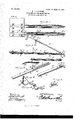
- Figure 1 is a top plan view of a portion (if a harvesterplatform, showing several of the improved attachments or grain-saving devices attached thereto. in position for operation.
- Fig. 2 is a sectional elevation of the same.
- Fig. 3 is a detail view showingin perspective the four members which when'put together constitute the improved device separated from each other.
- Fig.4 is a perspective view illustrating the clamp by means of which the improved device is attached to the harvester-platform in position for operation.
- Fig. 5 is adetail view of the point of the device.
- Fig. 6 is an enlarged perspective detail view of the sickleguard.
- FIG. 1 designates the main supporting-bar, which forms a part of my improved attachment.
- This bar is mainly triangular in cross-section, as will be clearly seen in Fig. 3, and it is provided with flanges 2 2, extending laterally from'its outer towardits inner end, which constitutes the point of attachment to the platform of the harvester, against which its upper flat side is squarely placed and secured by means of triangular brackets 3, having laterally-extending arms 4:, perforated for the reception of the securing-bolts 5.
- a triangular sickle-guard 6 is disposed upon the supporting-bar 1 a short distancein front of the ,platform.
- the frontend of the bar 1 is provided with a vertical slot 7 to receive a pair of adjusting-bolts 8 8, which extend through said slot and through corresponding openings 9 9 in a triangular trough-shaped extension 10, which engages the triangular under side of the supporting-bar and is secured thereto adj ust-ably by means of the bolts 8.
- This trough-shaped extension 10 is provided at its outer end with a detachable point 11, which istpreferably constructed of cast. metal and is provided near its point-ed front end with shoulders 12, forming points of abutment for the front end of the extension-i rough 10.
- the point 11 is tapered in an upward and rearward direction, as will be seen clearly in Fig.
- the bolt 18 serves for the securement of the extension-guide 20, which has a longitudinal slot 21 to permit it to be longitudinally adjustable.
- the said guide has a downturned point 22 in order to enable the grain to. be readily disengaged therefrom.
- the guiding means 15 and 20 beingconnected together, as shown, and secured td the seat 14, formed upon the point 15 of the device, will rise considerably above the front end of the platform and will thus serve not only to pick up the fallen grain and-to convey the sameto the cutting apparatus, but also to disentangle it and to maintain it in an approximately-upright position when itis presented to the cut ting apparatus, and causing it when severed to fall properly upon the platform, from whence it is conveyed in the usual manner to the binding apparatus when one is used.
- my improved apparatus a large proportion of the grain is not merely saved from destruction, but is saved in a manner that renders it capable of being handled along with the standing and perfect grain.
- the triangular sickle-guard which in the foregoing description has been designated 6, is preferably constructed of heavy sheet metal, a suitably-shaped blank being bent to the approximately-triangular shape shown in the drawings, the base of the triangle being provided with laterally-extending Wings or flanges 30', having bolt holes or perforations 31, whereby the said device may be secured in the position indicated in Figs. 2 and 3 of the drawings.
- This peculiarly-constructed sickle-guard will serve to prevent trash from lodging between the sickle-guard and the bar 1 next to the sickle-guard.
- the flanges or Wings 30 are bent to lit the device between the flanges 2 2 of the bar 1, and the peculiar construction of this part ot' the invention is particularly simple and convenient.
- a platform In a harvester, a platform, a supportingbar, triangular in cross-section and having upwardly-extending flanges, a sickle-guard mounted upon the upper side of said supporting-bar, and triangular su pporting-brackets securing said supporting-bar detachably to the under side of the platform.
- a grain-lifting attachment for harvesters comprising a supporting-bar having an adjustable extension, a return guide connected detachably with the point of said extension, and an extension connected adjustably with the upper rear end of said returnguide.
- a supporting-bar provided with longitudinal flanges at the edges thereof, asickleguard, approximately triangular, bent from sheet metal and provided at the base thereof with laterally-extending flanges bent to fit the. supporting-bar and against the flanges of the latter, and suitable connecting means.
Description
PATENTBD MAR. 17, 1903.
G. r. VOLLBORN. ATTACHMENT FOR HARVBSTERS.
APPLICATION FILED AUG. 22,1902. I O-MODEL.
azjwzzaorn, m m.
THE raonms PETERS 00.. PHOTO-UTNQ. WMHINO'I'ONA n. c
UNITED STATES PATENT FFICE.
ATTACHMENT FOR HARVESTERS.
. SPECIFICATION forming part of Lettersl'IPatent No. 723,084, dated March 1'7, 1903.
i Application filed August 22. 1902. Serial 110.120.670. (No modeli) To all whom it may concern:
Be it known that I, GUSTAVF. voimeonm.
a citizen ofthe United States, residing at Braman, in the county of Kay and Territory of Oklahoma, have invented a new and useful Attachment for Harvesters, of which the following is a specification.
This invention relates to an improved attachment for reapers, headers, and other harvesting-machines, having for its object tolift the fallen grain and carry it into the path of the cutting apparatus, thereby saving a large portion of the grain, which when machines of the ordinary construction are used is passed over and permitted to go to waste.
The invention consists in the improved construction and arrangement of the parts con stituting the device, which will be hereinafter more fully described, and particularly pointed out in the claims.
In the accompanying drawings, Figure 1 is a top plan view of a portion (if a harvesterplatform, showing several of the improved attachments or grain-saving devices attached thereto. in position for operation. Fig. 2 is a sectional elevation of the same. Fig. 3 isa detail view showingin perspective the four members which when'put together constitute the improved device separated from each other. Fig.4 is a perspective view illustrating the clamp by means of which the improved device is attached to the harvester-platform in position for operation. Fig. 5 is adetail view of the point of the device. Fig. 6 is an enlarged perspective detail view of the sickleguard.
Corresponding parts in the several figures are indicated by similar numerals of reference.
1 designates the main supporting-bar, which forms a part of my improved attachment. This bar is mainly triangular in cross-section, as will be clearly seen in Fig. 3, and it is provided with flanges 2 2, extending laterally from'its outer towardits inner end, which constitutes the point of attachment to the platform of the harvester, against which its upper flat side is squarely placed and secured by means of triangular brackets 3, having laterally-extending arms 4:, perforated for the reception of the securing-bolts 5. A triangular sickle-guard 6 is disposed upon the supporting-bar 1 a short distancein front of the ,platform.
The frontend of the bar 1 is provided with a vertical slot 7 to receive a pair of adjusting-bolts 8 8, which extend through said slot and through corresponding openings 9 9 in a triangular trough-shaped extension 10, which engages the triangular under side of the supporting-bar and is secured thereto adj ust-ably by means of the bolts 8. This trough-shaped extension 10 is provided at its outer end with a detachable point 11, which istpreferably constructed of cast. metal and is provided near its point-ed front end with shoulders 12, forming points of abutment for the front end of the extension-i rough 10. The point 11 is tapered in an upward and rearward direction, as will be seen clearly in Fig. 5, and it is provided on its upper side with shoulders 13, forming a seat 14 for the outer lower end of the return-guide 15, which is simply atriangular trough provided at one end with perforations 16 for the passage of the screws or other fastening means, whereby it isattached to the point 11 in the position clearly indicated in Fig. 2 of the drawings. At its upper rear end the trough is provided with a recess 17, which surrounds a perforation formed therein for the passage of a bolt 18,
the head of which, 19, is seated in the said recess. The bolt 18 serves for the securement of the extension-guide 20, which has a longitudinal slot 21 to permit it to be longitudinally adjustable. The said guide has a downturned point 22 in order to enable the grain to. be readily disengaged therefrom.
It will be seen that when the constituent parts of my device are put together, as shown, fore'instance, in Fig. 2, the supporting-arm 1 and its extension '10 extend a considerable distance in front of the platform and of the cutting apparatus, which latter has not, however, been shown in the drawings. The guiding means 15 and 20 beingconnected together, as shown, and secured td the seat 14, formed upon the point 15 of the device, will rise considerably above the front end of the platform and will thus serve not only to pick up the fallen grain and-to convey the sameto the cutting apparatus, but also to disentangle it and to maintain it in an approximately-upright position when itis presented to the cut ting apparatus, and causing it when severed to fall properly upon the platform, from whence it is conveyed in the usual manner to the binding apparatus when one is used. Thus it will be seen that by my improved apparatus a large proportion of the grain is not merely saved from destruction, but is saved in a manner that renders it capable of being handled along with the standing and perfect grain.
The triangular sickle-guard, which in the foregoing description has been designated 6, is preferably constructed of heavy sheet metal, a suitably-shaped blank being bent to the approximately-triangular shape shown in the drawings, the base of the triangle being provided with laterally-extending Wings or flanges 30', having bolt holes or perforations 31, whereby the said device may be secured in the position indicated in Figs. 2 and 3 of the drawings. This peculiarly-constructed sickle-guard will serve to prevent trash from lodging between the sickle-guard and the bar 1 next to the sickle-guard. The flanges or Wings 30 are bent to lit the device between the flanges 2 2 of the bar 1, and the peculiar construction of this part ot' the invention is particularly simple and convenient.
Having thus described my invention, I claim and desire to secure by Letters Patentof the United States-- 1. A grain-lifting attachment for harvesterscom prising a supporting-bar triangular in cross-section and having upwardly-extending flanges for a portion of its length, a triangular trough connected adjustably with said supporting-bar, a point at the front end of said trough, and return-guides connected detachably with said point.
2. In a harvester, a platform, a supportingbar, triangular in cross-section and having upwardly-extending flanges, a sickle-guard mounted upon the upper side of said supporting-bar, and triangular su pporting-brackets securing said supporting-bar detachably to the under side of the platform.
3. The combination with a supporting-bar, of the triangular trough-shaped extension, a tapering point, shouldered to form an abutment for the front end of said trough and having on its upper side additional shoulders forming a seat. and a triangular troughshaped rearWardly-extending guide mounted upon said seat and connected detachably with the point.
4. A grain-lifting attachment for harvesters comprising a supporting-bar having an adjustable extension, a return guide connected detachably with the point of said extension, and an extension connected adjustably with the upper rear end of said returnguide.
5. In a grain-lifting attachment for harvesters, a supporting-bar provided with longitudinal flanges at the edges thereof, asickleguard, approximately triangular, bent from sheet metal and provided at the base thereof with laterally-extending flanges bent to fit the. supporting-bar and against the flanges of the latter, and suitable connecting means.
In testimony that I claim the foregoing as my own I have hereto affixed my signature in the presence of two witnesses.
GUSTAV F. VOLLBORN.
Witnesses:
W. A. STOUGH, R. SHAUHOLTZER.
Priority Applications (1)
| Application Number | Priority Date | Filing Date | Title |
|---|---|---|---|
| US12067002A US723084A (en) | 1902-08-22 | 1902-08-22 | Attachment for harvesters. |
Applications Claiming Priority (1)
| Application Number | Priority Date | Filing Date | Title |
|---|---|---|---|
| US12067002A US723084A (en) | 1902-08-22 | 1902-08-22 | Attachment for harvesters. |
Publications (1)
| Publication Number | Publication Date |
|---|---|
| US723084A true US723084A (en) | 1903-03-17 |
Family
ID=2791598
Family Applications (1)
| Application Number | Title | Priority Date | Filing Date |
|---|---|---|---|
| US12067002A Expired - Lifetime US723084A (en) | 1902-08-22 | 1902-08-22 | Attachment for harvesters. |
Country Status (1)
| Country | Link |
|---|---|
| US (1) | US723084A (en) |
Cited By (3)
| Publication number | Priority date | Publication date | Assignee | Title |
|---|---|---|---|---|
| US20110047953A1 (en) * | 2009-09-02 | 2011-03-03 | Gebr. Schumacher Geratebaugesellschaft Mbh | Crop Lifter |
| US20130118140A1 (en) * | 2011-11-15 | 2013-05-16 | Dave Dietrich | Crop lifter with releasable tips |
| CN105307474A (en) * | 2013-05-01 | 2016-02-03 | 戴夫·迪特里希 | Crop lifter with angle and finger adjustment |
-
1902
- 1902-08-22 US US12067002A patent/US723084A/en not_active Expired - Lifetime
Cited By (9)
| Publication number | Priority date | Publication date | Assignee | Title |
|---|---|---|---|---|
| US20110047953A1 (en) * | 2009-09-02 | 2011-03-03 | Gebr. Schumacher Geratebaugesellschaft Mbh | Crop Lifter |
| US8112979B2 (en) * | 2009-09-02 | 2012-02-14 | Gebr. Schumacher Geratebaugesellschaft Mbh | Crop lifter |
| EP2324695A3 (en) * | 2009-09-02 | 2012-06-27 | Gebr. Schumacher Gerätebaugesellschaft mbH | Crop lifter |
| US20130118140A1 (en) * | 2011-11-15 | 2013-05-16 | Dave Dietrich | Crop lifter with releasable tips |
| US8991145B2 (en) * | 2011-11-15 | 2015-03-31 | Dave Dietrich | Crop lifter with releasable tips |
| CN105307474A (en) * | 2013-05-01 | 2016-02-03 | 戴夫·迪特里希 | Crop lifter with angle and finger adjustment |
| US20160150731A1 (en) * | 2013-05-01 | 2016-06-02 | Dave Dietrich | Crop lifter with angle and finger adjustment |
| US9642308B2 (en) * | 2013-05-01 | 2017-05-09 | Dave Dietrich | Crop lifter with angle and finger adjustment |
| CN105307474B (en) * | 2013-05-01 | 2017-09-29 | 戴夫·迪特里希 | The grain lifter adjusted with angled and finger |
Similar Documents
| Publication | Publication Date | Title |
|---|---|---|
| US2734332A (en) | fisher | |
| US723084A (en) | Attachment for harvesters. | |
| US791022A (en) | Attachment for finger-bars of mowers or harvesters. | |
| US3596454A (en) | Divider board for windrower | |
| US135495A (en) | Improvement in finger-bars for harvesters | |
| US1172033A (en) | Attachment for mowers. | |
| US1353450A (en) | Sickle | |
| US925863A (en) | Track-clearer for mowers. | |
| US650889A (en) | Swath-cleaner for mowing-machines. | |
| US1131091A (en) | Kafir-corn header. | |
| US1105084A (en) | Harvester attachment. | |
| US20110179760A1 (en) | Offset guard bolt attachment system | |
| US785878A (en) | Corn-harvester. | |
| US1121812A (en) | Harvester attachment. | |
| US361552A (en) | Frank w | |
| US241878A (en) | Sickle-bar for harvesters | |
| US745940A (en) | Supplemental finger for guards of cutting apparatus. | |
| US847568A (en) | Fender for harvesters. | |
| US643716A (en) | Corn-harvester. | |
| US728233A (en) | Attachment for mowing-machines. | |
| US783674A (en) | Stalk-cutter. | |
| US1057688A (en) | Harvester for pea-vines. | |
| US31183A (en) | Improvement in harvesters | |
| US592164A (en) | Machine for topping sorghum | |
| US960628A (en) | Plow-colter. |