US7228096B2 - Paper ejection guide of fixing mechanism for image forming apparatus having simple jam clearing structure - Google Patents
Paper ejection guide of fixing mechanism for image forming apparatus having simple jam clearing structure Download PDFInfo
- Publication number
- US7228096B2 US7228096B2 US11/151,204 US15120405A US7228096B2 US 7228096 B2 US7228096 B2 US 7228096B2 US 15120405 A US15120405 A US 15120405A US 7228096 B2 US7228096 B2 US 7228096B2
- Authority
- US
- United States
- Prior art keywords
- pawl
- separation pawl
- bracket
- separation
- members
- Prior art date
- Legal status (The legal status is an assumption and is not a legal conclusion. Google has not performed a legal analysis and makes no representation as to the accuracy of the status listed.)
- Expired - Fee Related
Links
Images


Classifications
-
- G—PHYSICS
- G03—PHOTOGRAPHY; CINEMATOGRAPHY; ANALOGOUS TECHNIQUES USING WAVES OTHER THAN OPTICAL WAVES; ELECTROGRAPHY; HOLOGRAPHY
- G03G—ELECTROGRAPHY; ELECTROPHOTOGRAPHY; MAGNETOGRAPHY
- G03G15/00—Apparatus for electrographic processes using a charge pattern
- G03G15/20—Apparatus for electrographic processes using a charge pattern for fixing, e.g. by using heat
- G03G15/2003—Apparatus for electrographic processes using a charge pattern for fixing, e.g. by using heat using heat
- G03G15/2014—Apparatus for electrographic processes using a charge pattern for fixing, e.g. by using heat using heat using contact heat
- G03G15/2017—Structural details of the fixing unit in general, e.g. cooling means, heat shielding means
- G03G15/2028—Structural details of the fixing unit in general, e.g. cooling means, heat shielding means with means for handling the copy material in the fixing nip, e.g. introduction guides, stripping means
-
- G—PHYSICS
- G03—PHOTOGRAPHY; CINEMATOGRAPHY; ANALOGOUS TECHNIQUES USING WAVES OTHER THAN OPTICAL WAVES; ELECTROGRAPHY; HOLOGRAPHY
- G03G—ELECTROGRAPHY; ELECTROPHOTOGRAPHY; MAGNETOGRAPHY
- G03G2215/00—Apparatus for electrophotographic processes
- G03G2215/20—Details of the fixing device or porcess
- G03G2215/2003—Structural features of the fixing device
- G03G2215/2016—Heating belt
- G03G2215/2025—Heating belt the fixing nip having a rotating belt support member opposing a pressure member
- G03G2215/2032—Heating belt the fixing nip having a rotating belt support member opposing a pressure member the belt further entrained around additional rotating belt support members
Definitions
- the present invention relates to a method and apparatus for forming an image. More particularly, the present invention relates to a method and apparatus for forming an image having a device capable of effectively fixing the image with reduced assembling steps and simple jam clearing operation.
- the fixing device includes a fixing roller or a fixing belt, a pressure roller or a pressure belt, and a nip part, so that the toner held on the recording medium is melt and fixed on the recording medium with pressure.
- the toner typically includes resin, which melts at the nip part. As a result, the toner tends to adhere to the fixing roller or the fixing belt. Therefore, various countermeasures are taken in order to prevent the toner from adhering to the surface of the fixing roller or the fixing belt.
- related art image forming apparatuses are provided with a sheet separation mechanism having separation pawls that allow the sheet, which tends to wind around the fixing roller or the fixing belt due to molten toner, to forcibly separate from the fixing roller or the fixing belt.
- the separation pawls do not completely prevent the sheet from winding around the fixing roller or the fixing belt.
- removal of the sheet is difficult.
- the sheet is torn and the torn sheet remains, which makes removal of the torn sheet difficult.
- a mechanism in which the separation pawls are released from the fixing roller or the fixing belt when the user removes a jammed sheet.
- the separation pawls are formed on a unit capable of being released from the nip part.
- Each separation pawl includes a pawl part and a rotation shaft, and the pawl part is biased by a spring, so that the pawl part pivoting around the rotation shaft is in contact with a surface of the fixing roller or the fixing belt.
- a separation pawl mechanism which brings the separation pawls close to the surface or separating the separation pawls from the surface, regulates each of the plurality of separation pawls, respectively. Accordingly, the number of parts increases which results in an increase in the number of assembly processes when assembling the fixing device. In addition, when doing maintenance, there is a disadvantage that a lot of time is required to replace the separation pawls.
- the present invention has been made in view of the above-mentioned and other disadvantages to address the above-discussed and other disadvantages.
- the present invention advantageously provides a novel image forming apparatus which includes an image forming mechanism forming a toner image on a recording sheet and a fixing mechanism.
- the fixing mechanism includes a pair of rotating members forming a nip portion and fixing the toner image onto the recording sheet with the nip under pressure and heat, and an ejection guide member swinging relative to the fixing mechanism.
- the fixing mechanism further includes a plurality of separation pawl members turning about a rotating shaft, a bracket having an elastic member, a pawl stopper, and a supporting shaft configured to support the bracket.
- the pawl stopper further includes a pressing member and a lever moving to allow the pawl stopper to turn.
- the supporting shaft further includes a center axis about which the bracket is freely pivotable.
- the ejection guide member is moved close to the nip portion, and then the tips of the plurality of separation pawl members are pressed to a surface of one of the pair of rotating members by swinging the ejection guide member.
- the pawl stopper is engaged with an engaging portion of the fixing mechanism in response to a motion of the lever in a fixing process.
- the pressing member presses the elastic member of the bracket to cause the bracket to turn to move the ejection guide member away from the nip portion.
- the tips of the plurality of separation pawl members are separated from the surface of the one of the pair of rotating members by turning the pawl stopper in a direction.
- the pawl stopper disengages from the engaging portion of the fixing mechanism in response to a different motion of the lever in a sheet jam recovery process.
- each of the plurality of separation pawl members includes a separation pawl and a separation pawl holder.
- the separation pawl holder further includes a pressing member for pressing the separation pawl in the direction in which the tips of the plurality of separation pawl members are pressed to the surface of the one of the pair of rotating members.
- the separation pawl member is configured to hold the separation pawl for rotation relative to the rotating shaft.
- the bracket includes a plurality of mounting portions.
- the mounting portion is further configured to mount the plurality of separation pawl members with the plurality of respective separation pawl holders pivotable about the plurality of respective mounting portions.
- Each of the plurality of mounting portions includes a stopper. The stopper is configured to regulate a movement of the separation pawl in the direction in which the tips of the plurality of separation pawl members are pressed to the surface of the one of the pair of rotating members.
- the rotating shaft includes a protrusion.
- the protrusion is configured to engage with the stopper when the separation pawl is lifted up due to a jam of the recording sheet. Accordingly, the tips of the plurality of separation pawl member are separated from the one of the pair of rotating members by at least a predetermined distance when a recording sheet jam occurs.
- the ejection guide member further includes an idle roller.
- the idle roller is configured so that the idle roller is kept in contact with the surface of the one of the pair of rotating members during the fixing process. Moreover, the idle roller allows the ejection guide member to swing about the center axis when the idle roller is kept in contact with the surface of the one of the pair of rotating members during a process of disengagement of the ejection guide member.
- FIG. 1 is a schematic sectional view illustrating a structure of a related art fixing device in which a paper ejection guide is released from the fixing device;
- FIG. 2 is a schematic sectional view illustrating a structure of a related art fixing device in which the paper ejection guide is returned to a locked position;
- FIG. 3 is an explanatory diagram schematically illustrating an exemplary structure of an image forming apparatus according to an embodiment of the present invention
- FIG. 4 is a sectional view illustrating a structure of a fixing device provided in the image forming apparatus of FIG. 3 , in which a paper ejection guide of the fixing device is at operational position;
- FIG. 6 is a perspective view illustrating how the separation pawl units are attached to the bracket in the fixing device according to FIG. 4 ;
- FIG. 7 is a perspective view illustrating a detailed structure of the plurality of separation pawl units in FIG. 6 ;
- FIG. 8 is a sectional view illustrating a motion of driven rollers provided to the separation pawl unit according to FIG. 4 ;
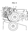
- FIG. 9 is a sectional view illustrating a condition in which the paper ejection guide is released from the operational position in the fixing device according to FIG. 4 ;
- FIG. 10 is a sectional view illustrating a condition in which the paper ejection guide is at an upward position following the operational position according to FIG. 9 ;
- FIG. 11 is a sectional view illustrating a condition in which the paper ejection guide is at a downward position following the upward position according to FIG. 10 ;
- FIGS. 12A and 12B are sectional views illustrating operations of the separation pawls when the jam is caused by a wound sheet in the fixing device.
- the fixing device includes a fixing roller 1 , a fixing belt 2 , a heating roller 3 , and a paper ejection guide 4 .
- the paper ejection guide 4 further includes a plurality of separation pawls 5 . It should be noted that the fixing device in the related art does not include a mechanism for separating the plurality of separation pawls 5 , which will be described later in detail. Accordingly, the operation for separating the separation pawls 5 will not occur.
- the paper ejection guide 4 is returned to a predetermined locked condition after dealing with the jammed sheet, as illustrated by a large arrow.
- the separation pawls 5 remain in a fully inwardly rotated position, then the tips of separation pawls 5 may bump into the fixing belt 2 , as illustrated by a small arrow, which will damage the fixing belt.
- a fixing device provided in an image forming apparatus according to an embodiment of the present invention will be explained below with reference to FIG. 3 .
- the image forming apparatus 100 includes a paper feed part 200 , an image forming part 300 , a document reading part 400 , and a document conveyance part 500 .
- the image forming apparatus 100 further includes a double-face reversal mechanism 70 , a paper ejection tray 80 , or the like.
- reference numerals 91 a through 91 d indicate paper feed cassettes, respectively.
- the image forming part 300 includes an image forming unit 30 , an exposure mechanism 40 , a transfer mechanism 50 , and a fixing mechanism, such as, a fixing device 60 .
- the image forming unit 30 includes four image forming mechanisms arranged in parallel for forming four colors of toner images such as Black (K), Cyan (C), Magenta (M), and Yellow (Y).
- the image forming unit 30 further includes photoconductors 31 K, 31 C, 31 M, and 31 Y, at central portions of the respective image forming units.
- each of the image forming units 30 includes a charging device, a developing device, and a cleaning device arranged around the photoconductor.
- the exposure mechanism 40 converts data read by the document reading part 400 or image signals transmitted from an external apparatus such as a personal computer (not illustrated) into optical signals such as laser light to form electrostatic latent images on the photoconductors 31 K, 31 C, 31 M, and 31 Y.
- the transfer mechanism 50 is configured to include an intermediate transfer belt 51 for sequentially superposing the toner images formed on the respective photoconductors 31 K, 31 C, 31 M, and 31 Y to hold the toner images thereon, so that a color toner image formed on the intermediate transfer belt 51 is transferred on a recording sheet.
- an intermediate transfer belt 51 for sequentially superposing the toner images formed on the respective photoconductors 31 K, 31 C, 31 M, and 31 Y to hold the toner images thereon, so that a color toner image formed on the intermediate transfer belt 51 is transferred on a recording sheet.
- another structure may be employed, for example, the toner images formed on the respective photoconductors 31 K, 31 C, 31 M, and 31 Y are directly transferred onto the recording sheet conveyed by a transfer conveyance belt.
- the fixing device 60 is configured to include a belt laid across rollers, which contain heaters therein, in a tensioned condition, and a pressure roller.
- the fixing device 60 further includes a nip part having both the belt and the pressure roller applying heat and pressure onto the toner on the recording sheet to fix the toner image. Otherwise, the fixing device 60 may use a pair of rollers or a pair of belts.
- the fixing device 60 includes two parts; one is the nip part and the other is a paper ejection guide 4 .
- the paper ejection guide 4 is locked with respect to a fixing belt 2 .
- FIG. 4 illustrates a condition in which tips of a plurality of separation pawls 5 are in contact with a surface of the fixing belt 2 in order to perform a fixing process.
- the nip part is configured in such a manner that the fixing device 60 includes a fixing roller 1 serving as a fixing member, an auxiliary roller 2 a arranged inside the fixing belt 2 , and a heat roller 3 serving as a pressure member.
- the fixing roller 1 and the heat roller 3 are arranged opposite to each other relative to the fixing belt 2 so that the fixing belt 2 can be pressurized by and between the fixing roller 1 and the pressure roller 3 .
- the respective rollers 1 , 2 a and 3 contain halogen heaters as heat sources therein and convey a sheet as a recording medium holding an unfixed toner image thereon, from a right side in FIG. 4 .
- the nip part supports the sheet from both sides thereof to heat the sheet, so that the toner image can be fixed.
- the paper ejection guide 4 in the fixing device 60 is configured to include a pair of fulcrum holes 4 a , a paper ejection guide main body 4 b , a plurality of separation pawls 5 , a plurality of rotation shafts 5 a , a plurality of projected bump pieces 5 b , a bracket 6 , a plate spring 6 a , a pawl stopper 8 , the plurality of separation pawl units 9 , an idle roller 8 c , and a spindle 21 .
- the paper ejection guide 4 is a pivot body.
- the paper ejection guide 4 is formed with respect to a main body of the fixing device 60 in such a manner that the paper ejection guide 4 pivots freely around the spindle 21 .
- the plate spring 6 a is an elastic member and the idle roller 8 c is an abutting member.
- the pair of fulcrum holes 4 a is used to receive a shaft (not illustrated) for supporting the paper ejection guide 4
- a center axis 4 c (illustrated in FIG. 5 ) extends through each center of the pair of fulcrum holes 4 a in FIG. 4 .
- the center axis 4 c will be explained below with reference to FIG. 5 .
- the bracket 6 includes a plurality of mounting portions 10 and is configured to pivot freely around the center of the pair of fulcrum holes 4 a of the paper ejection guide 4 .
- the paper ejection guide 4 is provided so that the paper ejection guide 4 is capable of being freely released and locked with respect to the nip part which includes the fixing belt 2 and the heat roller 3 .
- This mechanism can be used to remove the recording sheet jammed in the fixing device 60 .
- the spindle 21 is provided in the main body of the fixing device 60 .
- the spindle 21 supports the paper ejection guide 4 , which serves as the pivot body, with the plurality of separation pawls 5 to allow the paper ejection guide 4 to pivot freely around the spindle 21 .
- the separation pawls 5 will be described later in detail.
- the paper ejection guide main body 4 b is used for guiding the sheet toward an ejection roller (not illustrated) after the fixing of the toner image.
- the pawl stopper 8 includes a stopper main body 8 d , a lever 8 a , and a pressing member 8 b .
- the pawl stopper 8 is provided in such a manner that the pawl stopper 8 is capable of pivoting with respect to the paper ejection guide 4 .
- the receiving part 7 is provided at an appropriate position in the fixing device 60 in a manner that a position of the receiving part 7 is fixed.
- the receiver 7 is used for receiving the stopper main body 8 d that is formed on one end of the pawl stopper 8 .
- the pawl stopper 8 is capable of engaging and disengaging with the receiving part or engaging portion 7 by using the stopper main body or slant portion 8 d in response to a pivoting motion of the pawl stopper 8 .
- the pawl stopper 8 engages with the receiving part 7 , so that the paper ejection guide 4 can be locked with respect to the nip part.
- the lever 8 a is integrally provided at the pawl stopper 8 .
- the lever 8 a is used to release the locked condition of the paper ejection guide 4 .
- the pressing member 8 b is integrally provided on the pawl stopper 8 .
- the plate spring or elastic member 6 a is provided on the bracket 6 .
- the pressing member 8 b is configured to press against the plate spring 6 a to pivot the bracket 6 when the pawl stopper 8 pivots in a direction to release the paper ejection guide 4 , so that the tips of the separation pawls 5 attached to the bracket 6 are separated from surfaces of the fixing belt 2 and the heat roller 3 .
- the idle roller 8 c is configured to be provided in the paper ejection guide 4 , so that the paper ejection guide 4 pivots around the center of the pair of fulcrum holes 4 a in a condition in which the idle roller 8 c is in contact with the surface of the fixing belt 2 , while on the other hand, in the fixing process, the idle roller 8 c maintains a condition in which the idle roller 8 c is in contact with the surface of the fixing belt 2 .
- the stopper main body 8 d engages with the receiving part 7 by operation of the lever 8 a to hold the paper ejection guide 4 in a predetermined position, so that the tips of the separation pawls 5 are in contact with the surface of the fixing belt 2 .
- the fixing belt 2 is one of a pair of rotation bodies constituting the nip part. As a result, a condition illustrated in FIG. 4 is achieved. In other words, the condition in which the paper ejection guide 4 locks the nip part is achieved.
- the separation pawl units 9 are attached to the bracket 6 . Moreover, the separation pawl units 9 have a mechanism for attaching the separation pawls 5 .
- the mounting portions 10 are provided on the bracket 6 .
- the mounting portions 10 have a mechanism for mounting the separation pawl units 9 thereon.
- the stoppers 10 a are provided respectively on the mounting portions 10 and include a mechanism to bump against the projected bump pieces 5 b projected from a surface of the rotation shaft 5 a to separate the tips of the separation pawls 5 from the surface of the fixing roller 2 .
- the rotation shafts are provided on the separation pawl units 9 .
- the rotation shafts 5 a support the respective separation pawls 5 and include a mechanism around which the separation pawls 5 pivot.
- the projected bump piece 5 b will be described in explaining an operation for recovering from the jam of the recording sheet caused in the fixing device 60 .
- the projected bump piece 5 b is used for separating the tip of the separation pawl 5 from the surface of the fixing belt 2 .
- the idle roller 8 c is provided in the paper ejection guide 4 . In addition, the idle roller includes a mechanism to abut the surface of the fixing belt 2 .
- each of the separation pawls 5 is arranged on the bracket 6 .
- the bracket 6 is attached to the paper ejection guide 4 .
- the bracket 6 is configured to include a plurality of pair of opposing pieces 10 b to form the mounting portions 10 on which the separation pawl units 9 are mounted.
- Each pair of opposing pieces 10 b includes protrusions 10 c on a pair of opposing surfaces of the opposing pieces 10 b.
- the separation pawl units 9 provided with the separation pawls 5 are attached, in a pivotable manner, to the mounting portions 10 of the bracket 6 .
- the plurality of separation pawls 5 are attached to the bracket 6 .
- the bracket 6 is attached to the paper ejection guide 4 so that the bracket 6 is capable of pivoting around the center axis 4 c of the shaft supported by the pair of fulcrum holes 4 a .
- the bracket 6 is capable of pivoting around the center of the pair of fulcrum holes 4 a .
- the bracket 6 is biased so that the tips of the separation pawls 5 are in contact with the surface of the fixing belt 2 when the paper ejection guide 4 is settled at the locking position.
- the fixing device 60 allows for a reduction in the number of parts and number of assembly processes because the plurality of separation pawls 5 are provided in a single unit of the paper ejection guide 4 .
- each of the separation pawls unit 9 includes a separation pawl holder 9 a , which includes a pair of engaging holes 9 b and a plate spring 9 c .
- the pair of engaging holes 9 b is formed on the separation pawl holders 9 a .
- the pair of engaging holes 9 b is used for attaching the separation pawl units 9 to the respective mounting portions 10 .
- the plate springs 9 c are also formed on the separation pawl holders 9 a .
- the plate springs 9 c are used to bias the separation pawls 5 toward the surface of the fixing belt 2 , so that the tips of the separation pawls 5 are in contact with the surface of the fixing belt 2 .
- the separation pawl 5 When inserting the separation pawl units 9 into the mounting portion 10 provided on the bracket 6 , the separation pawl 5 is held at the predetermined position with the elasticity of the plate spring 9 c forming a part of the separation pawl holder 9 a .
- the pair of engaging holes 9 b is used as a center around which the separation pawl units 9 pivot to attach the separation pawl unit 9 to the bracket 6 to the mounting portion 10 .
- a pair of opposing pieces 10 b which constitute the mounting portion 10 , is provided with the protrusions 10 c on respective opposing inner surfaces thereof.
- the protrusions 10 c thus formed, oppose each other. Accordingly, when inserting the separation pawl unit 9 into the mounting portion 10 , inserting the protrusions 10 c into the pair of engaging holes 9 b together provide for a bearing structure similar to a pivot bearing.
- each separation pawl unit 9 attaching and detaching operations of each separation pawl unit 9 to each mounting portion 10 can be performed without using fastenings such as screws. Therefore, quick maintenance of the separation pawl units 9 can be achieved with ease. With this structure, when dealing with the jam caused by a wound sheet, a suitable treatment can be achieved.
- each one of the single separation pawl units 9 includes the separation pawl 5 , the rotation shaft 5 a , the projected bump piece 5 b , the separation pawl holder 9 a , the pair of engaging holes 9 b , the plate spring 9 c , a pair of rollers 11 , a rotation shaft 11 a , and a holder 12 .
- the pair of rollers 11 capable of freely rotating is provided at a position proximate to the separation pawl 5 . That is, the rollers 11 are provided on a rear side of a traveling direction of the recording sheet.
- both end portions of the rotation shaft 5 a are held by the separation pawl holder 9 a and the holder or sub-holder 12 .
- the holder 12 is used for holding the rotation shaft 5 a in conjunction with the separation pawl holder 9 a . Accordingly, the pair of rollers 11 is rotatable while contacting the recording sheet, which is traveling.
- the traveling recording sheet after completion of the toner fixing process is guided by means of the pair of rollers 11 .
- the roller holder 12 holds the pair of rollers 11 by holding both ends of the rotation shaft 11 a . That is, the holder 12 holds the rotation shaft 5 a for the separation pawl 5 together with the separation pawl holder 9 a , while supporting the pair of rollers 11 in a rotatable manner.
- a function of the pair of rollers 11 is to guide and convey the recording sheet, on a surface, which has the fixed toner image, and to prevent the recording sheet separated from the surface of the fixing belt 2 from slidably moving in conjunction with the separation pawl 5 .
- the pair of rollers 11 since the pair of rollers 11 is driven by the contact with the recording sheet to rotate, no substantial scraping friction is caused based on a relative velocity difference between the pair of rollers 11 and the recording sheet. Thus, irregularity in fixed toner image on the recording sheet can be prevented from occurring.
- the bracket 6 is provided with the plurality of separation pawls 5 , and the bracket 6 is held by the paper ejection guide 4 while freely pivots around the center of the pair of fulcrum holes 4 a .
- the bracket 6 is typically biased at a predetermined position.
- the paper ejection guide 4 maintains the locked condition by causing the pawl stopper 8 to engage with the receiving part 7 provided in the fixing device 60 in a fixed manner.
- the tips of the separation pawls 5 are slidably in contact with the fixing belt 2 , in a normal condition as illustrated in FIG. 4 , to separate the recording sheet having the toner image thereon, in the fixing device 60 .
- FIG. 10 a condition is illustrated in which the jammed recording sheet is released by opening the paper ejection guide 4 with respect to the fixing belt 2 . That is to say, the jammed recording sheet is dealt with by releasing the nip part of the fixing device 60 .
- the paper ejection guide 4 is released, in this condition, from the fixing belt 2 together with the plurality of separation pawls 5 .
- the jammed recording sheet is capable of being removed under the condition in which the paper ejection guide 4 is released.
- the paper ejection guide 4 provided with the plurality of separation pawls 5 is released to deal with the jammed recording sheet.
- the plurality of separation pawls 5 and the paper ejection guide 4 are released to widely open, a user can easily remove the jammed recording sheet.
- FIG. 11 a condition as follows is illustrated. Namely, the paper ejection guide 4 is returned, again, to a locked condition after completion of the removal of the jammed recording sheet is illustrated.
- the paper ejection guide 4 when returning the paper ejection guide 4 to the locked condition, separation of the bracket 6 provided with the plurality of separation pawls 5 from the fixing belt 2 is automatically performed.
- the paper ejection guide 4 can be returned to the condition illustrated in FIG. 4 without bumping of the plurality of separation pawls 5 against a surface of an abutting counterpart, such as the surface of fixing belt, by further pulling up the lever 8 a .
- the fixing process can be resumed without damaging the surface of the counterpart, such as the surface of the fixing belt 2 .
- the fixing device 60 when releasing and locking the paper ejection guide 4 in dealing with the jammed recording sheet, since the paper ejection guide 4 is configured to be forcibly separated from the fixing belt 2 , assembly of a device with a reduced number of parts and processes can be achieved. Accordingly, a reduction in assembly costs can be achieved.
- the jammed recording sheet can be suitably removed, with ease, from the fixing device 60 without causing the disadvantages described above.
- the structure thereof described in FIG. 4 is quite simple, a fixing device 60 with reduced costs is provided.
- the jammed recording sheet can be suitably removed, with ease, from the fixing device 60 without causing disadvantages, such as, where the plurality of separation pawls 5 come into contact with the counterpart with impact thereby damaging the counterpart.
- each separation pawl unit 9 is equipped with the separation pawl 5 , the rotation shaft 5 a for the separation pawl 5 , the projected bump piece 5 b projected from the rotation shaft 5 a , the separation pawl holder 9 a , the plate spring 9 c as the biasing member, the mounting portion 10 and the stopper 10 a .
- FIGS. 12A and 12B As illustrated in FIGS. 7 and 12A , each separation pawl unit 9 is equipped with the separation pawl 5 , the rotation shaft 5 a for the separation pawl 5 , the projected bump piece 5 b projected from the rotation shaft 5 a , the separation pawl holder 9 a , the plate spring 9 c as the biasing member, the mounting portion 10 and the stopper 10 a .
- each separation pawl unit 9 is capable of pivoting freely around the pair of engaging holes 9 b.
- Each separation pawl 5 pivots around the rotation shaft 5 a on which the projected bump piece 5 b is provided.
- the mounting portions 10 forming the bracket 6 as a part thereof are used for attaching the plurality of separation pawl units 9 to the bracket 6 .
- the stopper 10 a for regulating a pivoting motion in a direction which tends to be in contact with the fixing belt 2 is provided on each mounting portion 10 .
- the plurality of separation pawls 5 are raised by the jammed recording sheet in the jam, the plurality of separation pawl units 9 pivot to separate the tips of the respective separation pawls 5 from the surface of the fixing belt 2 , with the help of the stoppers 10 a.
- each separation pawl unit 9 the separation pawl 5 pivots freely around the rotation shaft 5 a , and the separation pawl unit 9 is equipped with the separation pawl holder 9 a , which holds the separation pawl 5 with the help of the rotation shaft 5 a .
- the separation pawl holder 9 a is made of metal having sufficient elasticity to operate in the manner described and the separation pawl holder 9 a has another center of rotation of the pair of engaging holes 9 b besides the rotation shaft 5 a around which the separation pawl 5 pivots.
- each separation pawl unit 9 is provided with the plate spring 9 c for holding the separation pawl 5 and the separation pawl holder 9 a at a predetermined position with the help of elasticity.
- the plurality of separation pawls 5 come in contact with the fixing belt 2 so as to prevent the recording sheet from winding around the fixing roller 2 .
- the recording sheet wound around the fixing belt 2 thrusts to raise the plurality of separation pawls 5 in a condition illustrated in FIG. 12B .
- the plurality separation pawls 5 are thrust in a direction in which the respective separation pawls 5 are acutely in contact with the fixing belt 2 .
- the respective separation pawl holders 9 a holding the respective separation pawls 5 pivot around the center of the pair of engaging holes 9 b in a counterclockwise direction. Accordingly, the holders 12 , the separation pawls 5 , and the projected bump pieces 5 b forming respective separation pawl holders 9 a move in an upper left direction, in an integrated fashion, as illustrated in FIG. 12B , before the respective separation pawls 5 acutely come in contact with the fixing belt 2 . That is to say, the holders 12 , the separation pawls 5 , and the projected bump pieces 5 b forming the separation pawl holders 9 a move in a direction indicated by a small arrow.
- the plurality of separation pawls 5 are prevented from moving in the internal direction in which the plurality of separation pawls 5 are acutely in contact with the fixing belt 2 . Additionally, in this case, since the stopper 10 a and the projected bump pieces 5 b are bumped with each other, the plurality of separation pawls 5 pivots around the rotation shafts 5 a in a clockwise direction. The above pivoting motion causes the tips of the plurality of separation pawls 5 to move in a direction so that the tips thereof are separated from the surface of the fixing belt 2 .
- the nip part is configured to include the fixing belt 2 used as a mechanism for fixing and the heat roller 3 used as a mechanism for fixing so that the recording sheet can be separated in the condition in which the plurality of separation pawls 5 are in contact with the fixing belt 2
- the mechanism for fixing and the mechanism for heating may be rollers. Additionally, when an endless belt is used as the fixing member and the heating member, a pressure roller pressing one endless belt to be in contact with the other endless belt is needed.
- the plurality of separation pawls 5 need to be configured in a manner that the plurality of separation pawls 5 come in contact with a surface of a particular mechanism, on which molten toner in the fixing process easily attaches, to separate the recording sheet.
- the plurality of separation pawls 5 are configured to come in contact with the surface of the fixing belt 2 so that the recording sheet can be easily adhered on the surface of the fixing belt 2 . Accordingly, when a fixing roller is used instead of the fixing belt 2 , the separation pawls 5 are required to be in contact with the surface of the fixing roller to separate the recording sheet.
- a heating method based on an induction heating method can be employed instead of the halogen heaters as the heat sources of the fixing roller 2 , the auxiliary roller 2 a , and the heat roller 3 .
- the induction heating method heat control with high accuracy can be achieved in addition to a heating operation with high thermal efficiency, so that high reliability in fixing the image with little thermal irregularity can be achieved.
- an auxiliary power source can be provided to supply the power, instead of the commercial power supply.
- an electrical two-layered capacitor including an electro-chemical capacitor can preferably be used.
- the present invention associated with the fixing device is widely applicable to a variety of devices that convey sheet-shaped materials, such as the recording sheet, and applicable to a variety of devices that supply heat to the sheet-shaped materials.
Landscapes
- Physics & Mathematics (AREA)
- General Physics & Mathematics (AREA)
- Fixing For Electrophotography (AREA)
Abstract
Description
Claims (15)
Applications Claiming Priority (2)
| Application Number | Priority Date | Filing Date | Title |
|---|---|---|---|
| JP2004175551A JP4291744B2 (en) | 2004-06-14 | 2004-06-14 | Fixing apparatus and image forming apparatus |
| JP2004-175551 | 2004-06-14 |
Publications (2)
| Publication Number | Publication Date |
|---|---|
| US20050276638A1 US20050276638A1 (en) | 2005-12-15 |
| US7228096B2 true US7228096B2 (en) | 2007-06-05 |
Family
ID=35460687
Family Applications (1)
| Application Number | Title | Priority Date | Filing Date |
|---|---|---|---|
| US11/151,204 Expired - Fee Related US7228096B2 (en) | 2004-06-14 | 2005-06-14 | Paper ejection guide of fixing mechanism for image forming apparatus having simple jam clearing structure |
Country Status (2)
| Country | Link |
|---|---|
| US (1) | US7228096B2 (en) |
| JP (1) | JP4291744B2 (en) |
Cited By (15)
| Publication number | Priority date | Publication date | Assignee | Title |
|---|---|---|---|---|
| US20080080909A1 (en) * | 2006-09-28 | 2008-04-03 | Masamichi Yamada | Fixing device and image forming apparatus including fixing device |
| US20090003897A1 (en) * | 2007-06-25 | 2009-01-01 | Masamichi Yamada | Sheet separation device, sheet conveyance apparatus, and image forming system |
| US20100189477A1 (en) * | 2009-01-27 | 2010-07-29 | Ricoh Company, Ltd. | Belt driving device, fixing device, and image forming apparatus |
| US20100226700A1 (en) * | 2009-03-05 | 2010-09-09 | Masamichi Yamada | Fixing device and image forming apparatus incorporating same |
| US20100303523A1 (en) * | 2009-06-02 | 2010-12-02 | Ricoh Company Ltd. | Image forming apparatus and fixing device with fine sheet separation function |
| US20110026986A1 (en) * | 2009-08-03 | 2011-02-03 | Takashi Yamanaka | Fixing apparatus and image forming apparatus including the same |
| US20110222874A1 (en) * | 2010-03-12 | 2011-09-15 | Masamichi Yamada | Fixing device and image forming apparatus including same |
| CN101819397B (en) * | 2009-02-27 | 2012-02-29 | 京瓷美达株式会社 | Fixing device and image forming apparatus comprising the same |
| US20120051805A1 (en) * | 2010-08-25 | 2012-03-01 | Naoto Suzuki | Media stripper, and fixing device and image forming apparatus employing same |
| US8515312B2 (en) | 2010-03-17 | 2013-08-20 | Ricoh Company, Ltd. | Fixing device and image forming apparatus including same |
| US8571455B2 (en) | 2010-10-04 | 2013-10-29 | Ricoh Company, Ltd. | Fixing device and image forming apparatus including same having a separation plate assembly |
| US8630556B2 (en) | 2010-03-15 | 2014-01-14 | Ricoh Company, Ltd. | Fixing device and image forming apparatus including same |
| US8744329B2 (en) | 2011-03-04 | 2014-06-03 | Ricoh Company, Ltd. | Fixing device and image forming apparatus incorporating same |
| US8811838B2 (en) | 2011-03-04 | 2014-08-19 | Ricoh Company, Ltd. | Fixing device and image forming apparatus incorporating same |
| US20150001791A1 (en) * | 2013-06-26 | 2015-01-01 | Kyocera Document Solutions Inc. | Sheet conveying device and image forming apparatus with same |
Families Citing this family (11)
| Publication number | Priority date | Publication date | Assignee | Title |
|---|---|---|---|---|
| KR100573764B1 (en) * | 2005-06-01 | 2006-04-26 | 삼성전자주식회사 | Image Forming Device and Fuser |
| KR100621099B1 (en) * | 2005-06-25 | 2006-09-07 | 삼성전자주식회사 | An image forming apparatus and a fixing apparatus for the image forming apparatus including a sheet release member |
| JP2008065264A (en) * | 2006-09-11 | 2008-03-21 | Ricoh Co Ltd | Fixing apparatus and image forming apparatus |
| JP5130721B2 (en) * | 2007-01-18 | 2013-01-30 | 富士ゼロックス株式会社 | Recording medium discharge unit opening / closing device and fixing device |
| JP5142582B2 (en) * | 2007-04-20 | 2013-02-13 | キヤノン株式会社 | Image heating device |
| CN102033470A (en) * | 2009-09-29 | 2011-04-27 | 株式会社东芝 | Fixing device, image forming apparatus, and method of removing residual toner |
| JP2014002243A (en) * | 2012-06-18 | 2014-01-09 | Ricoh Co Ltd | Fixation device and image formation device including the same |
| JP6242180B2 (en) * | 2012-12-04 | 2017-12-06 | キヤノン株式会社 | Image heating apparatus and image forming apparatus |
| JP6186727B2 (en) | 2013-01-08 | 2017-08-30 | 株式会社リコー | Guide member separation mechanism, fixing device, and image forming apparatus |
| JP6089735B2 (en) | 2013-01-31 | 2017-03-08 | 株式会社リコー | Fixing apparatus and image forming apparatus |
| JP6422563B2 (en) * | 2017-12-28 | 2018-11-14 | キヤノン株式会社 | Fixing device |
Citations (14)
| Publication number | Priority date | Publication date | Assignee | Title |
|---|---|---|---|---|
| JPH05165364A (en) | 1991-12-13 | 1993-07-02 | Ricoh Co Ltd | Fixing device |
| JPH08220923A (en) | 1995-02-20 | 1996-08-30 | Ricoh Co Ltd | Separation claw release device |
| JPH09160426A (en) | 1995-12-11 | 1997-06-20 | Konica Corp | Fixing device and placing device therefor |
| US6088558A (en) | 1998-03-05 | 2000-07-11 | Ricoh Company, Ltd. | Method and apparatus for suppressing belt shift in an image forming apparatus |
| US6091926A (en) | 1998-03-27 | 2000-07-18 | Ricoh Company, Ltd. | Fixing device using a belt for an image forming apparatus |
| US6351619B1 (en) | 1999-04-23 | 2002-02-26 | Ricoh Company, Ltd. | Image forming apparatus, belt type fixing device and heating control |
| JP2002145503A (en) | 2000-08-30 | 2002-05-22 | Canon Inc | Recording material separating device, fixing device, and image forming device |
| US6522858B1 (en) * | 2000-10-04 | 2003-02-18 | Heidelberger Druckmaschinen Ag | Upper skive plate and method of installation in the fuser section of an electrophotographic machine |
| US6553204B1 (en) | 1999-07-23 | 2003-04-22 | Ricoh Company, Ltd. | Fixing device for fixing a toner image in an image forming apparatus |
| US6577840B2 (en) | 1999-12-02 | 2003-06-10 | Ricoh Company, Ltd. | Method and apparatus for image forming capable of effectively performing an image fixing process |
| JP2003255750A (en) | 2002-03-04 | 2003-09-10 | Ricoh Co Ltd | Fixing device and image forming device |
| US20030215270A1 (en) | 2002-04-11 | 2003-11-20 | Masamichi Yamada | Fixing device and image forming apparatus including the same |
| US6658229B2 (en) * | 2000-08-30 | 2003-12-02 | Canon Kabushiki Kaisha | Recording material separating apparatus of which separating member is retractable in operative association with guide |
| US6813464B2 (en) * | 2002-03-01 | 2004-11-02 | Ricoh Company, Ltd. | Fixing device with a peeler and biasing devices and image forming apparatus including the same |
-
2004
- 2004-06-14 JP JP2004175551A patent/JP4291744B2/en not_active Expired - Lifetime
-
2005
- 2005-06-14 US US11/151,204 patent/US7228096B2/en not_active Expired - Fee Related
Patent Citations (15)
| Publication number | Priority date | Publication date | Assignee | Title |
|---|---|---|---|---|
| JPH05165364A (en) | 1991-12-13 | 1993-07-02 | Ricoh Co Ltd | Fixing device |
| JPH08220923A (en) | 1995-02-20 | 1996-08-30 | Ricoh Co Ltd | Separation claw release device |
| JPH09160426A (en) | 1995-12-11 | 1997-06-20 | Konica Corp | Fixing device and placing device therefor |
| US6088558A (en) | 1998-03-05 | 2000-07-11 | Ricoh Company, Ltd. | Method and apparatus for suppressing belt shift in an image forming apparatus |
| US6091926A (en) | 1998-03-27 | 2000-07-18 | Ricoh Company, Ltd. | Fixing device using a belt for an image forming apparatus |
| US6351619B1 (en) | 1999-04-23 | 2002-02-26 | Ricoh Company, Ltd. | Image forming apparatus, belt type fixing device and heating control |
| US6553204B1 (en) | 1999-07-23 | 2003-04-22 | Ricoh Company, Ltd. | Fixing device for fixing a toner image in an image forming apparatus |
| US6577840B2 (en) | 1999-12-02 | 2003-06-10 | Ricoh Company, Ltd. | Method and apparatus for image forming capable of effectively performing an image fixing process |
| US6865363B2 (en) | 1999-12-02 | 2005-03-08 | Ricoh Company, Ltd. | Method and apparatus for image forming capable of effectively performing an image fixing process |
| JP2002145503A (en) | 2000-08-30 | 2002-05-22 | Canon Inc | Recording material separating device, fixing device, and image forming device |
| US6658229B2 (en) * | 2000-08-30 | 2003-12-02 | Canon Kabushiki Kaisha | Recording material separating apparatus of which separating member is retractable in operative association with guide |
| US6522858B1 (en) * | 2000-10-04 | 2003-02-18 | Heidelberger Druckmaschinen Ag | Upper skive plate and method of installation in the fuser section of an electrophotographic machine |
| US6813464B2 (en) * | 2002-03-01 | 2004-11-02 | Ricoh Company, Ltd. | Fixing device with a peeler and biasing devices and image forming apparatus including the same |
| JP2003255750A (en) | 2002-03-04 | 2003-09-10 | Ricoh Co Ltd | Fixing device and image forming device |
| US20030215270A1 (en) | 2002-04-11 | 2003-11-20 | Masamichi Yamada | Fixing device and image forming apparatus including the same |
Non-Patent Citations (1)
| Title |
|---|
| Computer translation of cited reference JP09-160426a. * |
Cited By (25)
| Publication number | Priority date | Publication date | Assignee | Title |
|---|---|---|---|---|
| US7751768B2 (en) | 2006-09-28 | 2010-07-06 | Ricoh Company, Ltd. | Fixing device and image forming apparatus including fixing device |
| US20080080909A1 (en) * | 2006-09-28 | 2008-04-03 | Masamichi Yamada | Fixing device and image forming apparatus including fixing device |
| US20090003897A1 (en) * | 2007-06-25 | 2009-01-01 | Masamichi Yamada | Sheet separation device, sheet conveyance apparatus, and image forming system |
| US7890039B2 (en) | 2007-06-25 | 2011-02-15 | Ricoh Company, Ltd. | Sheet separation device, sheet conveyance apparatus, and image forming system |
| US20100189477A1 (en) * | 2009-01-27 | 2010-07-29 | Ricoh Company, Ltd. | Belt driving device, fixing device, and image forming apparatus |
| US8346146B2 (en) | 2009-01-27 | 2013-01-01 | Ricoh Company, Ltd. | Belt driving device, fixing device, and image forming apparatus |
| CN101819397B (en) * | 2009-02-27 | 2012-02-29 | 京瓷美达株式会社 | Fixing device and image forming apparatus comprising the same |
| US20100226700A1 (en) * | 2009-03-05 | 2010-09-09 | Masamichi Yamada | Fixing device and image forming apparatus incorporating same |
| US8526871B2 (en) | 2009-03-05 | 2013-09-03 | Ricoh Company, Ltd. | Fixing device and image forming apparatus incorporating same |
| US8358959B2 (en) | 2009-03-05 | 2013-01-22 | Ricoh Company, Ltd. | Fixing device and image forming apparatus incorporating same |
| US8320808B2 (en) | 2009-06-02 | 2012-11-27 | Ricoh Company, Ltd. | Image forming apparatus and fixing device with fine sheet separation function |
| US20100303523A1 (en) * | 2009-06-02 | 2010-12-02 | Ricoh Company Ltd. | Image forming apparatus and fixing device with fine sheet separation function |
| US20110026986A1 (en) * | 2009-08-03 | 2011-02-03 | Takashi Yamanaka | Fixing apparatus and image forming apparatus including the same |
| US8280289B2 (en) | 2009-08-03 | 2012-10-02 | Sharp Kabushiki Kaisha | Fixing apparatus and image forming apparatus including the same |
| US20110222874A1 (en) * | 2010-03-12 | 2011-09-15 | Masamichi Yamada | Fixing device and image forming apparatus including same |
| US8909074B2 (en) * | 2010-03-12 | 2014-12-09 | Ricoh Company, Limited | Fixing device and image forming apparatus including same |
| US8630556B2 (en) | 2010-03-15 | 2014-01-14 | Ricoh Company, Ltd. | Fixing device and image forming apparatus including same |
| US8515312B2 (en) | 2010-03-17 | 2013-08-20 | Ricoh Company, Ltd. | Fixing device and image forming apparatus including same |
| US20120051805A1 (en) * | 2010-08-25 | 2012-03-01 | Naoto Suzuki | Media stripper, and fixing device and image forming apparatus employing same |
| US8744327B2 (en) * | 2010-08-25 | 2014-06-03 | Ricoh Company, Ltd. | Media stripper, and fixing device and image forming apparatus employing same |
| US8571455B2 (en) | 2010-10-04 | 2013-10-29 | Ricoh Company, Ltd. | Fixing device and image forming apparatus including same having a separation plate assembly |
| US8744329B2 (en) | 2011-03-04 | 2014-06-03 | Ricoh Company, Ltd. | Fixing device and image forming apparatus incorporating same |
| US8811838B2 (en) | 2011-03-04 | 2014-08-19 | Ricoh Company, Ltd. | Fixing device and image forming apparatus incorporating same |
| US20150001791A1 (en) * | 2013-06-26 | 2015-01-01 | Kyocera Document Solutions Inc. | Sheet conveying device and image forming apparatus with same |
| US9016690B2 (en) * | 2013-06-26 | 2015-04-28 | Kyocera Document Solutions Inc. | Sheet conveying device and image forming apparatus with same |
Also Published As
| Publication number | Publication date |
|---|---|
| JP4291744B2 (en) | 2009-07-08 |
| JP2005352382A (en) | 2005-12-22 |
| US20050276638A1 (en) | 2005-12-15 |
Similar Documents
| Publication | Publication Date | Title |
|---|---|---|
| US7228096B2 (en) | Paper ejection guide of fixing mechanism for image forming apparatus having simple jam clearing structure | |
| US11579563B2 (en) | Process cartridge and image forming apparatus | |
| US8369743B2 (en) | Process cartridge and electrophotographic image forming apparatus | |
| JP4134985B2 (en) | Image forming apparatus and cartridge | |
| US7330682B2 (en) | Apparatus capable of applying a high fixing-nip pressure which is easily released when a recording sheet is stuck in a fixing mechanism | |
| CN1770043B (en) | Image forming apparatus | |
| US7676176B2 (en) | Image forming apparatus including cover and supporting unit | |
| US8606156B2 (en) | Fixing unit and image forming apparatus using fixing unit | |
| US20150307307A1 (en) | Image forming apparatus | |
| US7756458B2 (en) | Fusing member rejuvenating method and system in a toner image producing machine | |
| US6658222B2 (en) | Method and apparatus for image forming capable of effectively performing a fixing process | |
| JP4681933B2 (en) | Image forming apparatus | |
| JP6765806B2 (en) | Process cartridge, image forming device and separating member | |
| JP2010020234A (en) | Cleaning apparatus using web sheet | |
| JP3887937B2 (en) | Development device | |
| US10203649B2 (en) | Bearing device and transferring device | |
| JP4401515B2 (en) | Image forming apparatus | |
| JP4179897B2 (en) | Image forming apparatus | |
| JP5861372B2 (en) | Image forming apparatus | |
| JP2025082768A (en) | Belt conveying device and image forming apparatus | |
| JP2022026273A (en) | Image forming device | |
| JPH0683231A (en) | Fixing device and image forming device |
Legal Events
| Date | Code | Title | Description |
|---|---|---|---|
| AS | Assignment |
Owner name: RICOH COMPANY, LTD., JAPAN Free format text: ASSIGNMENT OF ASSIGNORS INTEREST;ASSIGNOR:YAMADA, MASAMICHI;REEL/FRAME:016691/0850 Effective date: 20050613 |
|
| FEPP | Fee payment procedure |
Free format text: PAYOR NUMBER ASSIGNED (ORIGINAL EVENT CODE: ASPN); ENTITY STATUS OF PATENT OWNER: LARGE ENTITY |
|
| STCF | Information on status: patent grant |
Free format text: PATENTED CASE |
|
| FEPP | Fee payment procedure |
Free format text: PAYER NUMBER DE-ASSIGNED (ORIGINAL EVENT CODE: RMPN); ENTITY STATUS OF PATENT OWNER: LARGE ENTITY Free format text: PAYOR NUMBER ASSIGNED (ORIGINAL EVENT CODE: ASPN); ENTITY STATUS OF PATENT OWNER: LARGE ENTITY |
|
| FPAY | Fee payment |
Year of fee payment: 4 |
|
| FPAY | Fee payment |
Year of fee payment: 8 |
|
| FEPP | Fee payment procedure |
Free format text: MAINTENANCE FEE REMINDER MAILED (ORIGINAL EVENT CODE: REM.); ENTITY STATUS OF PATENT OWNER: LARGE ENTITY |
|
| LAPS | Lapse for failure to pay maintenance fees |
Free format text: PATENT EXPIRED FOR FAILURE TO PAY MAINTENANCE FEES (ORIGINAL EVENT CODE: EXP.); ENTITY STATUS OF PATENT OWNER: LARGE ENTITY |
|
| STCH | Information on status: patent discontinuation |
Free format text: PATENT EXPIRED DUE TO NONPAYMENT OF MAINTENANCE FEES UNDER 37 CFR 1.362 |
|
| FP | Lapsed due to failure to pay maintenance fee |
Effective date: 20190605 |