US7204338B2 - Handle knob for industrial vehicle - Google Patents
Handle knob for industrial vehicle Download PDFInfo
- Publication number
- US7204338B2 US7204338B2 US10/470,227 US47022703A US7204338B2 US 7204338 B2 US7204338 B2 US 7204338B2 US 47022703 A US47022703 A US 47022703A US 7204338 B2 US7204338 B2 US 7204338B2
- Authority
- US
- United States
- Prior art keywords
- steering wheel
- knob
- switch
- industrial vehicle
- vehicle according
- Prior art date
- Legal status (The legal status is an assumption and is not a legal conclusion. Google has not performed a legal analysis and makes no representation as to the accuracy of the status listed.)
- Expired - Lifetime, expires
Links
- 230000005540 biological transmission Effects 0.000 claims abstract description 32
- 238000004891 communication Methods 0.000 claims description 24
- 238000001514 detection method Methods 0.000 claims description 14
- 230000008054 signal transmission Effects 0.000 claims 4
- 230000003213 activating effect Effects 0.000 claims 2
- 230000004397 blinking Effects 0.000 claims 1
- 238000009877 rendering Methods 0.000 claims 1
- 230000008021 deposition Effects 0.000 description 40
- 238000010586 diagram Methods 0.000 description 28
- 230000000994 depressogenic effect Effects 0.000 description 16
- 238000000034 method Methods 0.000 description 12
- 238000012545 processing Methods 0.000 description 12
- 230000008569 process Effects 0.000 description 8
- 230000004913 activation Effects 0.000 description 7
- 238000013461 design Methods 0.000 description 7
- 210000003813 thumb Anatomy 0.000 description 7
- 210000003811 finger Anatomy 0.000 description 6
- 230000008859 change Effects 0.000 description 5
- 230000007246 mechanism Effects 0.000 description 5
- 238000003860 storage Methods 0.000 description 5
- 230000000881 depressing effect Effects 0.000 description 3
- 230000006872 improvement Effects 0.000 description 3
- 239000003086 colorant Substances 0.000 description 2
- 230000008602 contraction Effects 0.000 description 2
- 238000006073 displacement reaction Methods 0.000 description 2
- 239000012530 fluid Substances 0.000 description 2
- 238000003780 insertion Methods 0.000 description 2
- 230000037431 insertion Effects 0.000 description 2
- 230000007935 neutral effect Effects 0.000 description 2
- 239000011347 resin Substances 0.000 description 2
- 229920005989 resin Polymers 0.000 description 2
- 230000008685 targeting Effects 0.000 description 2
- 230000005856 abnormality Effects 0.000 description 1
- 230000009471 action Effects 0.000 description 1
- 238000004364 calculation method Methods 0.000 description 1
- 239000003990 capacitor Substances 0.000 description 1
- 238000006243 chemical reaction Methods 0.000 description 1
- 230000000694 effects Effects 0.000 description 1
- 239000000446 fuel Substances 0.000 description 1
- 239000004973 liquid crystal related substance Substances 0.000 description 1
- 238000004519 manufacturing process Methods 0.000 description 1
- 238000003909 pattern recognition Methods 0.000 description 1
- 238000002360 preparation method Methods 0.000 description 1
Images


Classifications
-
- G—PHYSICS
- G05—CONTROLLING; REGULATING
- G05G—CONTROL DEVICES OR SYSTEMS INSOFAR AS CHARACTERISED BY MECHANICAL FEATURES ONLY
- G05G1/00—Controlling members, e.g. knobs or handles; Assemblies or arrangements thereof; Indicating position of controlling members
- G05G1/08—Controlling members for hand actuation by rotary movement, e.g. hand wheels
- G05G1/10—Details, e.g. of discs, knobs, wheels or handles
-
- B—PERFORMING OPERATIONS; TRANSPORTING
- B60—VEHICLES IN GENERAL
- B60L—PROPULSION OF ELECTRICALLY-PROPELLED VEHICLES; SUPPLYING ELECTRIC POWER FOR AUXILIARY EQUIPMENT OF ELECTRICALLY-PROPELLED VEHICLES; ELECTRODYNAMIC BRAKE SYSTEMS FOR VEHICLES IN GENERAL; MAGNETIC SUSPENSION OR LEVITATION FOR VEHICLES; MONITORING OPERATING VARIABLES OF ELECTRICALLY-PROPELLED VEHICLES; ELECTRIC SAFETY DEVICES FOR ELECTRICALLY-PROPELLED VEHICLES
- B60L1/00—Supplying electric power to auxiliary equipment of vehicles
- B60L1/003—Supplying electric power to auxiliary equipment of vehicles to auxiliary motors, e.g. for pumps, compressors
-
- B—PERFORMING OPERATIONS; TRANSPORTING
- B60—VEHICLES IN GENERAL
- B60L—PROPULSION OF ELECTRICALLY-PROPELLED VEHICLES; SUPPLYING ELECTRIC POWER FOR AUXILIARY EQUIPMENT OF ELECTRICALLY-PROPELLED VEHICLES; ELECTRODYNAMIC BRAKE SYSTEMS FOR VEHICLES IN GENERAL; MAGNETIC SUSPENSION OR LEVITATION FOR VEHICLES; MONITORING OPERATING VARIABLES OF ELECTRICALLY-PROPELLED VEHICLES; ELECTRIC SAFETY DEVICES FOR ELECTRICALLY-PROPELLED VEHICLES
- B60L50/00—Electric propulsion with power supplied within the vehicle
- B60L50/50—Electric propulsion with power supplied within the vehicle using propulsion power supplied by batteries or fuel cells
- B60L50/60—Electric propulsion with power supplied within the vehicle using propulsion power supplied by batteries or fuel cells using power supplied by batteries
- B60L50/66—Arrangements of batteries
-
- B—PERFORMING OPERATIONS; TRANSPORTING
- B60—VEHICLES IN GENERAL
- B60L—PROPULSION OF ELECTRICALLY-PROPELLED VEHICLES; SUPPLYING ELECTRIC POWER FOR AUXILIARY EQUIPMENT OF ELECTRICALLY-PROPELLED VEHICLES; ELECTRODYNAMIC BRAKE SYSTEMS FOR VEHICLES IN GENERAL; MAGNETIC SUSPENSION OR LEVITATION FOR VEHICLES; MONITORING OPERATING VARIABLES OF ELECTRICALLY-PROPELLED VEHICLES; ELECTRIC SAFETY DEVICES FOR ELECTRICALLY-PROPELLED VEHICLES
- B60L8/00—Electric propulsion with power supply from forces of nature, e.g. sun or wind
- B60L8/003—Converting light into electric energy, e.g. by using photo-voltaic systems
-
- B—PERFORMING OPERATIONS; TRANSPORTING
- B62—LAND VEHICLES FOR TRAVELLING OTHERWISE THAN ON RAILS
- B62D—MOTOR VEHICLES; TRAILERS
- B62D1/00—Steering controls, i.e. means for initiating a change of direction of the vehicle
- B62D1/02—Steering controls, i.e. means for initiating a change of direction of the vehicle vehicle-mounted
- B62D1/04—Hand wheels
- B62D1/043—Hand wheels with a device allowing single-hand operation of the steering wheel
-
- B—PERFORMING OPERATIONS; TRANSPORTING
- B66—HOISTING; LIFTING; HAULING
- B66F—HOISTING, LIFTING, HAULING OR PUSHING, NOT OTHERWISE PROVIDED FOR, e.g. DEVICES WHICH APPLY A LIFTING OR PUSHING FORCE DIRECTLY TO THE SURFACE OF A LOAD
- B66F9/00—Devices for lifting or lowering bulky or heavy goods for loading or unloading purposes
- B66F9/06—Devices for lifting or lowering bulky or heavy goods for loading or unloading purposes movable, with their loads, on wheels or the like, e.g. fork-lift trucks
- B66F9/075—Constructional features or details
- B66F9/20—Means for actuating or controlling masts, platforms, or forks
-
- B—PERFORMING OPERATIONS; TRANSPORTING
- B60—VEHICLES IN GENERAL
- B60L—PROPULSION OF ELECTRICALLY-PROPELLED VEHICLES; SUPPLYING ELECTRIC POWER FOR AUXILIARY EQUIPMENT OF ELECTRICALLY-PROPELLED VEHICLES; ELECTRODYNAMIC BRAKE SYSTEMS FOR VEHICLES IN GENERAL; MAGNETIC SUSPENSION OR LEVITATION FOR VEHICLES; MONITORING OPERATING VARIABLES OF ELECTRICALLY-PROPELLED VEHICLES; ELECTRIC SAFETY DEVICES FOR ELECTRICALLY-PROPELLED VEHICLES
- B60L2200/00—Type of vehicles
- B60L2200/40—Working vehicles
- B60L2200/42—Fork lift trucks
-
- H—ELECTRICITY
- H01—ELECTRIC ELEMENTS
- H01H—ELECTRIC SWITCHES; RELAYS; SELECTORS; EMERGENCY PROTECTIVE DEVICES
- H01H2207/00—Connections
- H01H2207/048—Inductive or infrared coupling
-
- Y—GENERAL TAGGING OF NEW TECHNOLOGICAL DEVELOPMENTS; GENERAL TAGGING OF CROSS-SECTIONAL TECHNOLOGIES SPANNING OVER SEVERAL SECTIONS OF THE IPC; TECHNICAL SUBJECTS COVERED BY FORMER USPC CROSS-REFERENCE ART COLLECTIONS [XRACs] AND DIGESTS
- Y02—TECHNOLOGIES OR APPLICATIONS FOR MITIGATION OR ADAPTATION AGAINST CLIMATE CHANGE
- Y02P—CLIMATE CHANGE MITIGATION TECHNOLOGIES IN THE PRODUCTION OR PROCESSING OF GOODS
- Y02P90/00—Enabling technologies with a potential contribution to greenhouse gas [GHG] emissions mitigation
- Y02P90/60—Electric or hybrid propulsion means for production processes
-
- Y—GENERAL TAGGING OF NEW TECHNOLOGICAL DEVELOPMENTS; GENERAL TAGGING OF CROSS-SECTIONAL TECHNOLOGIES SPANNING OVER SEVERAL SECTIONS OF THE IPC; TECHNICAL SUBJECTS COVERED BY FORMER USPC CROSS-REFERENCE ART COLLECTIONS [XRACs] AND DIGESTS
- Y02—TECHNOLOGIES OR APPLICATIONS FOR MITIGATION OR ADAPTATION AGAINST CLIMATE CHANGE
- Y02T—CLIMATE CHANGE MITIGATION TECHNOLOGIES RELATED TO TRANSPORTATION
- Y02T10/00—Road transport of goods or passengers
- Y02T10/60—Other road transportation technologies with climate change mitigation effect
- Y02T10/70—Energy storage systems for electromobility, e.g. batteries
-
- Y—GENERAL TAGGING OF NEW TECHNOLOGICAL DEVELOPMENTS; GENERAL TAGGING OF CROSS-SECTIONAL TECHNOLOGIES SPANNING OVER SEVERAL SECTIONS OF THE IPC; TECHNICAL SUBJECTS COVERED BY FORMER USPC CROSS-REFERENCE ART COLLECTIONS [XRACs] AND DIGESTS
- Y02—TECHNOLOGIES OR APPLICATIONS FOR MITIGATION OR ADAPTATION AGAINST CLIMATE CHANGE
- Y02T—CLIMATE CHANGE MITIGATION TECHNOLOGIES RELATED TO TRANSPORTATION
- Y02T10/00—Road transport of goods or passengers
- Y02T10/60—Other road transportation technologies with climate change mitigation effect
- Y02T10/7072—Electromobility specific charging systems or methods for batteries, ultracapacitors, supercapacitors or double-layer capacitors
-
- Y—GENERAL TAGGING OF NEW TECHNOLOGICAL DEVELOPMENTS; GENERAL TAGGING OF CROSS-SECTIONAL TECHNOLOGIES SPANNING OVER SEVERAL SECTIONS OF THE IPC; TECHNICAL SUBJECTS COVERED BY FORMER USPC CROSS-REFERENCE ART COLLECTIONS [XRACs] AND DIGESTS
- Y02—TECHNOLOGIES OR APPLICATIONS FOR MITIGATION OR ADAPTATION AGAINST CLIMATE CHANGE
- Y02T—CLIMATE CHANGE MITIGATION TECHNOLOGIES RELATED TO TRANSPORTATION
- Y02T90/00—Enabling technologies or technologies with a potential or indirect contribution to GHG emissions mitigation
- Y02T90/10—Technologies relating to charging of electric vehicles
- Y02T90/16—Information or communication technologies improving the operation of electric vehicles
-
- Y—GENERAL TAGGING OF NEW TECHNOLOGICAL DEVELOPMENTS; GENERAL TAGGING OF CROSS-SECTIONAL TECHNOLOGIES SPANNING OVER SEVERAL SECTIONS OF THE IPC; TECHNICAL SUBJECTS COVERED BY FORMER USPC CROSS-REFERENCE ART COLLECTIONS [XRACs] AND DIGESTS
- Y10—TECHNICAL SUBJECTS COVERED BY FORMER USPC
- Y10T—TECHNICAL SUBJECTS COVERED BY FORMER US CLASSIFICATION
- Y10T74/00—Machine element or mechanism
- Y10T74/20—Control lever and linkage systems
- Y10T74/20576—Elements
- Y10T74/20732—Handles
- Y10T74/20834—Hand wheels
- Y10T74/20864—Handles
Definitions
- the present invention relates to a wheel knob for an industrial vehicle and an industrial vehicle.
- a steering wheel knob is formed on the steering wheel of a forklift, such as a reach type so that steering can be done with one hand.
- switches mounted on an instrument panel are operated while doing a steering operation depending on the circumstance.
- the steering wheel knob 200 is provided with a creep drive switch 201 and when the creep drive switch 201 is depressed, its detection signal is output to a control circuit 202 . Then, when receiving the detection signal from the switch 201 , the control circuit 202 controls a three-phase power converter 203 and drives a drive motor 204 to cause a vehicle to drive in creep mode.
- Japanese Unexamined Patent Publication No. 2000-72000 discloses a steering wheel which can permit a switch operation while a steering wheel knob is being held.
- This steering wheel 206 is a steering wheel for handicapped persons and a grip holder 207 is attached to the steering wheel 206 .
- Attached to the grip holder 207 are a grip (steering wheel knob) 208 and a switch case 212 which has three switches 209 to 211 for a horn, winker and light.
- the various switches 209 to 211 are operated by stretching a finger while holding the grip 208 , which can ensure a steering operation and a switch operation simultaneously.
- the creep drive switch 201 is connected to the control circuit 202 by a wire. While the switch is provided on the steering wheel knob 200 , therefore, the wires (harnesses) that connect the switch 201 to the control circuit 202 may suffer frictional wear or interfere when the steering wheel is operated, thereby raising a problem of disconnecting the line. In case where the steering wheel knob 200 is made movable relatively to a steering wheel 205 , the problem becomes particularly noticeable.
- Japanese Unexamined Patent Publication No. 2000-72000 describes that the switches 209 to 211 are connectable to the electric circuitry (not shown) for control wirelessly. While the switches 209 to 211 are radio-communicatable and the grip 208 and the switches 209 to 211 can be operated at the same time, however, fingers should be let go of the grip 208 at the time of the switch operation, the hold on the grip 208 would become loose, making the steering operation unstable.
- the present invention has been devised in view of the above-described problems and aims at providing a steering wheel knob for an industrial vehicle and an industrial vehicle which eliminates the need for wiring in the steering wheel knob and can secure the gripped state of the steering wheel knob even in a case where a steering operation and another operation can be performed at the same time.
- a wireless type communication section capable of executing at least one of transmission and reception by radio communication is built in a knob.
- the wireless type communication section capable of executing at least one of transmission and reception by radio communication
- FIG. 1 is an exemplary cross-sectional view of a steering wheel knob of a forklift according to a first embodiment of the present invention.
- FIG. 2 is a perspective view seeing a driver's seat from the front.
- FIG. 3 is a perspective view showing the state in which the steering wheel knob is used.
- FIG. 4 is a plan view seeing the driver's seat from above.
- FIG. 5 is a perspective view of the forklift.
- FIG. 6 is an exemplary side view showing a cargo carrying work of the forklift.
- FIG. 7 is a plan view of a multi lever.
- FIG. 8 is an explanatory diagram about automatic fork position control.
- FIG. 9 is a block circuit diagram illustrating the electrical structure of the forklift.
- FIG. 10( a ) is a front view of a mark.
- FIG. 10( b ) is a front view of a template corresponding to FIG. 10( a ).
- FIG. 10( c ) is a front view of a mark.
- FIG. 10( d ) is a front view of a template corresponding to FIG. 10( c ).
- FIG. 11 is an explanatory diagram about double location matching.
- FIG. 12( a ) is a screen diagram showing a screen coordinate system set on a screen.
- FIG. 12( b ) is a display diagram showing real coordinates.
- FIG. 13 is an explanatory diagram for explaining a calculation method at the time of obtaining a camera position.
- FIG. 14( a ) is a front view of the display screen showing a load pickup mode before forks are positioned.
- FIG. 14( b ) is a front view of the display screen showing the load pickup mode after the forks are positioned.
- FIG. 15( a ) is a front view of the display screen showing a load deposition mode before the forks are positioned.
- FIG. 15( b ) is a front view of the display screen showing the load deposition mode after the forks are positioned.
- FIG. 16 is a side view of a steering wheel in another example.
- FIG. 17 is a plan view of FIG. 16 .
- FIG. 18 is a schematic structural diagram of a forklift according to a different example.
- FIG. 19 is a schematic structural diagram of a forklift according to another example.
- FIG. 20 is a schematic structural diagram of a forklift according to a further example.
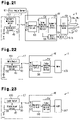
- FIG. 21 is a schematic structural diagram of a forklift according to a still further example.
- FIG. 22 is a schematic structural diagram of a forklift according to a yet still further example.
- FIG. 23 is a schematic structural diagram of a forklift according to a yet still further example.
- FIG. 24 is a schematic structural diagram of a forklift according to a yet still further example.
- FIG. 25 is a schematic structural diagram of a forklift according to a yet still further example.
- FIG. 26 is a schematic structural diagram of a forklift according to a yet still further example.
- FIG. 27 is a schematic structural diagram of a forklift according to a yet still further example.
- FIG. 28 is a schematic structural diagram of a forklift according to a yet still further example.
- FIG. 29 is a schematic structural diagram of a forklift according to a yet still further example.
- FIG. 30 is a schematic structural diagram of a forklift according to a yet still further example.
- FIG. 31 is a schematic structural diagram of a forklift according to a yet still further example.
- FIG. 32( a ) is a perspective view of a steering wheel knob according to a different example.
- FIG. 32( b ) is a perspective view of a steering wheel knob according to another example.
- FIG. 32( c ) is a perspective view of a steering wheel knob according to a further example.
- FIG. 33 is a front perspective view of a driver's seat in a still further example.
- FIG. 34 is a schematic side view of a steering wheel in a still further example.
- FIG. 35 is a schematic electrical structural diagram of a forklift according to prior art.
- FIG. 36 is a partly enlarged view of a steering wheel according to prior art.
- FIGS. 1 to 15 One embodiment of a steering wheel knob for an industrial vehicle and an industrial vehicle in which the present invention is embodied will be described below with reference to FIGS. 1 to 15 .
- FIG. 5 is a perspective view of a forklift 1 .
- the reach type forklift truck (hereinafter simply written as “forklift”) 1 as an industrial vehicle (vehicle) has a pair of left and right reach legs 3 on the front side of a vehicle body (equipment platform) 2 and a mast assembly 4 is movable (reach operation) forward and rearward along the reach legs 3 .
- a reach cylinder 5 is disposed on the vehicle body 2 and the reach cylinder 5 causes the mast assembly 4 to do the reach operation.
- the mast assembly 4 has forks 6 as a cargo carrying apparatus and the positions of the forks 6 are adjusted in the forward and reverse directions in accordance with the reach operation of the mast assembly 4 .
- a mast 7 of the mast assembly 4 is a three-level mast comprising an outer mast 7 a , a middle mast 7 b and an inner mast 7 c and is a telescopic type (full free type) whose drive sources are a center lift cylinder 8 a and a pair of left and right lift cylinders 8 b , 8 b (only one shown).
- a center lift cylinder 8 a is driven first, only a carriage 9 is lifted upward and as the mast 7 does slide expansion and contraction after the carriage 9 reaches the topmost position of the inner mast 7 c , the carriage 9 moves upward and downward.
- the forks 6 are attached to the carriage 9 and their positions are adjusted upward and downward in accordance with the slide expansion and contraction of the mast 7 .
- a side shifter 10 is mounted on the carriage 9 so that the side shifter 10 is movable rightward and leftward as a side shift cylinder 11 (see FIG. 9 ) is driven.
- the positions of the forks 6 are adjusted rightward and leftward according to the side shifting of the side shifter 10 .
- a tilt cylinder 12 (see FIG. 9 ) is connected to the carriage 9 and as the tilt cylinder 12 performs a tilt operation, the tilt angles of the forks 6 are adjusted.
- Front wheels (driven wheels) 13 a are attached to the distal end portions of the individual reach legs 3 and rear wheels (driving wheels) 13 b are attached to the vehicle body 2 .
- the rear wheels 13 b serve as steered wheels and are driven by the power from a drive motor 14 which is driven by a battery 2 a installed in the vehicle body 2 as a power supply.
- a stand-up type driver's seat 15 is provided at the rear right portion of the vehicle body 2 and as a steering wheel 16 is operated, the rear wheels 13 b are steered.
- the steering wheel 16 is made of a resin and a steering wheel knob 17 of a resin which is gripped by a driver at the time of operating the steering wheel 16 is formed on the top surface of the steering wheel 16 .
- the forklift 1 has a camera lifting unit 18 assembled to the front center portion of the side shifter 10 in order to support the positioning operation for the forks 6 in a high position (high lifted height range).
- the camera lifting unit 18 has a camera unit 20 incorporating a camera (CCD camera) 19 as image pickup means so that the camera unit 20 is elevated between a storage position in which it is stored in a housing 21 assembled to the front center portion of the carriage 9 and a lift-down position where it protrudes from the lower end of the housing 21 .
- CCD camera camera
- the position of the camera unit 20 is adjusted in such a way that the unit comes to the storage position at the time of executing a load pickup work to pick up a load (pallet) and comes to the lift-down position at the time of executing a load deposition work to put down the load carried on the forks 6 at a predetermined place.
- the camera unit 20 can pick up the image of a cargo carrying work area in front of the forks 6 with a pickup portion (lens) 22 of the camera 19 .
- An image pickup window 23 is formed in the front lower portion of the housing 21 and the image of the cargo carrying work area can be picked up through the image pickup window 23 even from the storage position. That is, the camera 19 can pick up an image of the front (forward) of the forks 6 from two positions, the storage position and the lift-down position, by means of the camera 19 .
- the camera lifting unit 18 moves leftward and rightward, together with the forks 6 .
- a liquid crystal display device (hereinafter simply written as “display device”) 25 as display means is attached to a roof 24 , which covers the upper portion of the vehicle body 2 , at a location where the driver standing on the driver's seat 15 can see well.
- the image of an area in front of the forks 6 which is picked up by the camera 19 at the time of cargo carrying work is displayed on a display screen 25 a of the display device 25 .
- the driver can do a cargo carrying work while viewing the display screen 25 a of the display device 25 .
- FIG. 6 is an exemplary side view when a cargo carrying work is executed by the forklift 1 equipped with the camera 19 .
- the cargo carrying work for loads 26 is carried out with the loads placed on pallets 27 .
- a rack 28 where the loads 26 are to be placed has a multi-stage structure and some has an overall height equal to or higher than twice the height of the forklift 1 . If the rack 28 has such a great overall height, there may be cases where the driver cannot see the cargo carrying work from the driver's seat 15 at the time of doing a cargo carrying work at a shelf portion 29 located high.
- the forklift 1 equipped with the camera 19 picks up the image of an area in front of the forks 6 by the camera 19 and automatically position the forks 6 based on the picked-up image, thereby supporting the cargo carrying work.
- FIG. 7 is a plan view of a multi lever.
- a multi lever 31 is provided on the instrument panel 30 .
- the multi lever 31 can ensure all the operations concerning the driving work and cargo carrying work and has a plurality of operation sections.
- the multi lever 31 has a lever body 33 which tilts forward and backward along a slot 32 on the instrument panel 30 , and the lever body 33 returns to the neutral position, approximately perpendicular to the panel surface when it is not operated, by the urging force of a spring (not shown).
- Attached to the upper end portion of the lever body 33 is a grip portion 34 in a state where it tilts by about 30 degrees to 60 degrees to the vehicle's widthwise direction.
- a lifting knob 35 approximately cylindrical in shape is rotatably provided at the left end portion of the grip portion 34 .
- a seesaw switch 36 , a cross switch 37 and an activation switch 38 are provided respectively at the front edge of the left portion of the grip portion 34 , the back of the left portion of the grip portion 34 and the front of the left portion of the grip portion 34 .
- the multi lever 31 is operated with the right hand, and the lifting knob 35 or the cross switch 37 can be manipulated with the thumb while holding the grip portion 34 and the seesaw switch 36 or the activation switch 38 can be manipulated with the index finger.
- the cross switch 37 is operable in four directions, up, down, left and right, the upward and downward operations manipulate the tilting of the mast 7 and the leftward and rightward operations manipulate the side shifting. That is, pushing an upper end portion 37 a of the cross switch 37 with the thumb tilts the forks 6 forward and pushing a lower end portion 37 b of the cross switch 37 tilts the forks 6 rearward. Further, pushing a right end portion 37 c of the cross switch 37 with the thumb shifts the forks 6 rightward and pushing a left end portion 37 d of the cross switch 37 shifts the forks 6 leftward.
- FIG. 1 is an exemplary cross-sectional view of the steering wheel knob 17
- FIG. 2 is a perspective view seeing the driver's seat 15 from the front.
- the steering wheel 16 has a steering shaft 40 coupled to the vehicle body 2 via a bearing 40 a .
- Formed in the diametric end portion of the steering wheel 16 is an engage hole 41 to which a shaft portion 43 sticking out of a knob body 42 is coupled via a bearing 44 .
- the steering wheel knob 17 is relatively rotatable around the shaft portion 43 in the directions of arrows in FIG. 2 with respect to the steering wheel 16 .
- the outer shape of the knob body 42 extends in an approximately rectangular parallelepiped shape away from the shaft portion 43 , and the extending portion is formed as a holding portion 45 to hold the steering wheel knob 17 .
- a load pickup mode switch 46 Formed on a flat surface portion 42 a of the knob body 42 are a load pickup mode switch 46 and a load deposition mode switch 47 for manually setting the operation mode for the cargo carrying work.
- Those two switches 46 and 47 are wireless switches and can radio-communicate with a controller 48 (see FIG. 9 ) to be discussed later. Of the two switches 46 and 47 , depressing the load pickup mode switch 46 sets the operation mode to the “load pickup mode” and depressing the load deposition mode switch 47 sets the operation mode to the “load deposition mode”.
- the knob body 42 incorporates a transmission circuit 49 , an antenna 50 and a battery 51 .
- the load pickup mode switch 46 and the load deposition mode switch 47 are connected to the input side of the transmission circuit 49 via signal lines 46 a and 47 a and the antenna 50 is connected to the output side via a signal line 50 a .
- the transmission circuit 49 sends a switch signal corresponding to the switch 46 , 47 to the controller 48 via the antenna 50 by radio wave.
- a retaining portion 42 b for retaining the battery 51 is formed in the knob body 42 .
- the retaining portion 42 b is openable and closable with a lid 52 and when the battery 51 is dead, battery replacement is to be performed with the lid 52 removed.
- the battery 51 is the power supply for the wireless switches on the steering wheel knob 17 , i.e., feeds power to the load pickup mode switch 46 , the load deposition mode switch 47 and the transmission circuit 49 .
- the two switches 46 and 47 , the transmission circuit 49 and the antenna 50 constitute input means and the switches 46 and 47 are equivalent to the operation section (mode changeover switch) and the transmission circuit 49 and the antenna 50 to the transmission section.
- FIG. 3 is a perspective view showing the state in which the steering wheel knob 17 is used and FIG. 4 is a plan view seeing the driver's seat 15 from above.
- the steering wheel knob 17 is held with a left hand in a holding state where the thumb of the left hand is positioned at the flat surface portion 42 a of the knob body 42 with the remaining four fingers gripping the holding portion 45 .
- one of the load pickup mode switch 46 and the load deposition mode switch 47 is manipulated with the thumb of the left hand.
- the driver standing on the driver's seat 15 grips the multi lever 31 with the right hand with the right elbow placed down and grips the steering wheel knob 17 with the left hand.
- This can allow the driver to simultaneously operate the multi lever 31 and the steering wheel 16 (steering wheel knob 17 ). Because the steering wheel knob 17 turns around the shaft portion 43 (see FIG. 1 ) at the time of turning the steering wheel 16 , the steering wheel knob 17 takes a suitable position to the driver however much the steering wheel 16 is turned.
- FIG. 8 is an explanatory diagram about automatic fork positioning control which automatically positions the forks.
- the pallets 27 and the rack 28 are affixed with marks Ml and M 2 as marks to obtain the relative positions of the forks 6 to the pallets 27 and the rack 28 .
- the mark M 1 is affixed to the center between two insertion holes 27 a , 27 a at a side (front side) of the pallet 27 .
- the mark M 2 is affixed to the front center of the shelf portion 29 of the rack 28 .
- the mark M 1 affixed to the pallet 27 and the mark M 2 affixed to the rack 28 are identical in pattern, the black and white of the patterns are inverted.
- the forks 6 are automatically positioned, targeting the mark M 1 affixed on the pallet 27 , in such a way as to face the insertion holes 27 a of the pallet 27 .
- the forks 6 are automatically positioned, targeting the mark M 2 affixed on the rack 28 , in such a way that the forks 6 are positioned at a predetermined height above a shelf surface (deposition surface) 29 a of the shelf portion 29 (a height of, for example, 10 to 20 cm above the shelf surface 29 a ) and the middle point of the two forks 6 come to nearly the same position as the mark M 2 .
- the positioning of the forks 6 is carried out by moving the forks 6 upward or downward (in a z direction in the diagram) by driving the lift cylinder 8 b and by moving the forks 6 leftward or rightward (in a y direction in the diagram) by driving the side shift cylinder 11 .
- FIG. 9 illustrates the electrical structure of the forklift 1 .
- the forklift 1 has the controller 48 which has an image control section 53 , a cargo handling control section 54 , drive circuits 55 and 56 and a solenoid drive circuit 57 .
- An upper-limit position detection switch 58 , a lower-limit position detection switch 59 , a height sensor 60 , a load weight sensor 61 and a tilt angle sensor 62 are connected to the input side of the cargo handling control section 54 .
- a lever potentiometer which detects the amount of displacement in the lever body 33 of the multi lever 31
- a knob potentiometer (neither illustrated) which detects the amount of displacement in the lifting knob 35 and various switches 36 to 38 (see FIG. 7 ) are connected to the input side of the cargo handling control section 54 .
- a camera lifting motor 63 and a cargo carrying motor (electric motor) 64 are connected to the output side of the cargo handling control section 54 respectively via the drive circuits 55 and 56 .
- the solenoids of various electromagnetic proportional valves 65 a to 65 d assembled to an oil control valve 65 are connected to the output side of the cargo handling control section 54 via the solenoid drive circuit 57 .
- Those electromagnetic proportional valves 65 a to 65 d are respectively connected to the lift cylinders 8 a , 8 b , the reach cylinder 5 , the side shift cylinder 11 and the tilt cylinder 12 .
- the cargo handling control section 54 performs current value control of the electromagnetic proportional valves 65 a to 65 d and drive control of the cargo carrying motor 64 based on an operation signal from the multi lever 31 .
- a cargo carrying pump (hydraulic pump) 64 a As the action of the cargo carrying motor 64 drives a cargo carrying pump (hydraulic pump) 64 a , a hydraulic fluid is supplied to the oil control valve 65 .
- the individual electromagnetic proportional valves 65 a to 65 d corresponding to the manipulation are subjected to proportional control based on an operation signal from the multi lever 31 , so that the lift cylinders 8 a , 8 b , the reach cylinder 5 , the side shift cylinder 11 and the tilt cylinder 12 are hydraulically controlled to carry out the lifting operation, reaching operation, side shifting operation and tilting operation of the forks 6 .
- the height sensor 60 detects if the forks 6 are at a height (lifted height) equal to or higher than the set height and comprises a height switch which is switched on or off when, for example, the carriage 9 comes to the topmost position of the inner mast 7 c and the inner mast 7 c slides.
- the height sensor 60 may be a sensor which can continuously detect the lifted height of the forks 6 .
- a reel type height sensor that detects the amount of rotation of a reel from which a wire is fed out or wound up in accordance with the elevation of the carriage 9 and an ultrasonic type height sensor that detects a cylinder stroke from the measured time from the point an ultrasonic wave traveling in the fluids in the lift cylinders 8 a , 8 b has been reflected at the piston to the point it returns may be employed as the height sensor 60 .
- the load weight sensor 61 detects the weight of a load (load weight) carried on the forks 6 and comprises a pressure sensor which detects the hydraulic pressures in the lift cylinders 8 a , 8 b in this embodiment.
- the load weight sensor 61 outputs a detection signal which has a voltage value according to the weight of the load on the forks 6 .
- the tilt angle sensor 62 detects the tilt angle with the angle of the forks 6 in the horizontal position (horizontal angle) as a reference, and comprises, for example, a potentiometer.
- the forklift 1 has an automatic fork positioning system (lock-on system) 66 .
- the lock-on system 66 executes an image recognition process on the marks M 1 and M 2 based on image data picked up by the camera 19 or automatic position control on the forks 6 with the set mark M 1 (M 2 ) as a target.
- the lock-on system 66 comprises units needed for image recognition process of the marks and automatic position control of the forks 6 , such as the camera 19 , the image control section 53 , the cargo handling control section 54 , the display device 25 , the activation switch 38 and the wireless switch mechanisms which set the operation mode through a manual operation, and the like.
- the cargo handling control section 54 sets the operation mode of the lock-on system 66 to one of the load pickup mode and the load deposition mode based on the detected value from the load weight sensor 61 . That is, when the load obtained from the detected value from the load weight sensor 61 is equal to or smaller than the set value (load W ? set value Wo), the cargo handling control section 54 determines that “no load” which is no loads carried on the forks 6 and sets the operation mode to the “load pickup mode”. When the load obtained from the detected value from the load weight sensor 61 exceeds the set value (load W>set value Wo), on the other hand, the cargo handling control section 54 determines that “load present” which is a load carried on the forks 6 and sets the operation mode to the “load deposition mode”.
- the operation mode is automatically set based on the load on the forks 6 irrespective of the operation by the operator.
- the detected value from the load weight sensor 61 includes the weight of the carriage 9 or the like, a value which is the detected value with an empty load or a little margin added to that detected value is set to the set value Wo.
- the process of setting the operation mode is executed every given time (e.g., several tens of msec).
- the setting of the operation mode of the lock-on system 66 is not limited to automatic execution based on the detected value from the load weight sensor 61 but it can be manually set by depressing the two switches 46 and 47 of the steering wheel knob 17 , which will be elaborated below.
- the cargo handling control section 54 is connected with a reception circuit 68 having an antenna 67 .
- the antenna 67 and the reception circuit 68 are disposed in the instrument panel 30 .
- the reception circuit 68 receives a radio wave, launched from the antenna 50 of the steering wheel knob 17 , via the antenna 67 and outputs a reception signal corresponding to the radio wave to the cargo handling control section 54 .
- the intensity of the radio wave transmitted from the steering wheel knob 17 is set in such a way that the entire area of the vehicle body 2 is the transmission range.
- the manual setting has a priority.
- the antenna 67 and the reception circuit 68 constitute a reception section.
- the reception circuit 68 receives the switch signal for setting the load pickup mode, transmitted by radio wave from the antenna 50 , via the antenna 67 and outputs a reception signal according to that signal to the cargo handling control section 54 . Based on the reception signal, the cargo handling control section 54 sets the operation mode of the lock-on system 66 to the “load pickup mode”.
- the reception circuit 68 receives the switch signal for setting the load deposition mode by radio wave via the antennae 50 and 67 , and outputs a reception signal according to that signal to the cargo handling control section 54 . Based on the reception signal, the cargo handling control section 54 sets the operation mode of the lock-on system 66 to the “load deposition mode”.
- the cargo handling control section 54 performs the lifting control of the camera unit 20 and the automatic fork position control.
- the cargo handling control section 54 executes the automatic position control only when the height of the forks 6 detected by the height sensor 60 is equal to or greater than the set height (e.g., about 2 meters).
- the cargo handling control section 54 places the camera unit 20 in the storage position in load pickup mode and places the camera unit 20 in the lift-down position in load deposition mode.
- the driving of the camera lifting motor 63 is stopped when the camera unit 20 reaches the upper limit position and the upper-limit position detection switch 58 is turned on and when the camera unit 20 reaches the lower limit position and the lower-limit position detection switch 59 is turned on.
- the camera 19 is connected to the input side of the image control section 53 and the display device 25 is connected to the output side.
- the display device 25 has the display screen 25 a and a speaker 69 as output means, and the image control section 53 displays the image (video image) on the display screen 25 a and causes the speaker 69 to generate a predetermined sound.
- the image control section 53 executes image processing based on image data acquired from the camera 19 .
- the image control section 53 has a display processing section 70 , an image processing section 71 , a drawing display section 72 , a drawing data memory section 73 and a voice processing section 74 .
- the display processing section 70 outputs a video signal, input from the camera 19 , to the display device 25 in such a way that the image picked up by the camera 19 is displayed on the screen.
- the image processing section 71 receives the image data from the display processing section 70 , performs an image recognition process based on the image data and calculates the coordinates of the marks M 1 and M 2 , the coordinates of a shift target point 75 or the like on the display screen 25 a of the display device 25 (the screen coordinate system shown in FIG. 12( a )).
- the drawing display section 72 displays the drawing of the shift target point 75 and a target line 76 (see FIG. 14 for both) or the like on the display screen 25 a as drawing data stored in the drawing data memory section 73 .
- the drawing display section 72 respectively displays, on the display screen 25 a , the “load pickup mode” (see FIG. 14 ) when the operation mode is the load pickup mode and the “load deposition mode” (see FIG. 15 ) when the operation mode is the load deposition mode.
- the image processing section 71 has an image recognition processing section 77 , a template memory section 78 and a screen coordinate position calculating section 79 .
- the screen coordinate position calculating section 79 has a mark position calculating section 80 and a shift target point calculating section 81 .
- the cargo handling control section 54 has a real coordinate position calculating section 82 and a deviation amount calculating section 83 . The following will describe the contents of the processes performed by the image control section 53 and the cargo handling control section 54 at the time of the automatic fork position control according to FIGS. 10 to 13 .
- the template memory section 78 Stored in the template memory section 78 are a template T 1 for the mark M 1 and a template T 2 for the mark M 2 . That is, the mark M 1 shown in FIG. 10( a ) is constituted by two patterns P 1 , P 1 aligned next to each other shown in FIG. 10( b ). The mark M 2 shown in FIG. 10( c ) is constituted by two patterns P 2 , P 2 aligned next to each other shown in FIG. 10( d ). A mark indicates an overall design and a pattern indicates two designs constituting a mark.
- the templates T 1 and T 2 to be used in the pattern matching process have the same designs as the patterns P 1 and P 2 .
- the patterns P 1 , P 2 of the two marks M 1 and M 2 are designed with the black and white patterns inverted to each other.
- Each pattern P 1 , P 2 has a design separated into white and black colors by a plurality of boundary lines extending straight radially around one point.
- Each pattern P 1 , P 2 in the present embodiment has a design separated into white and black colors by four areas defined by the two diagonal lines of a square. It is to be noted that the contour line equivalent to the sides of the rectangular shape of the template is not a part of the design.
- the image recognition processing section 77 can recognize the marks M 1 , M 2 through pattern matching using only a single template T 1 , T 2 .
- the templates T 1 , T 2 are set to predetermined sizes from which the marks M 1 , M 2 should be recognized, and the marks M 1 , M 2 picked up within a predetermined distance are all recognizable.
- FIG. 12( a ) is a screen diagram showing a screen coordinate system set on the screen and the coordinates are handled in the units of pixels in the screen coordinate system.
- H is the number of horizontal pixels of the display screen 25 a of the display device 25
- V is the number of vertical pixels of the display screen 25 a .
- FIG. 12( b ) is a display diagram showing real coordinates and has a similar relation to the screen diagram in FIG. 12( a ).
- the image recognition section 77 Based on image data acquired from the camera 19 , the image recognition section 77 performs an image recognition process (pattern matching process) at two locations of the patterns P 1 , P 1 as shown in FIG. 11 by using the template T 1 in load pickup mode and the template T 2 in load deposition mode. Then, the image recognition section 77 recognizes the marks M 1 and M 2 on the display screen 25 a of the display device 25 or in the screen coordinate system.
- an image recognition process pattern matching process
- the image recognition section 77 performs matching on the two patterns P 1 , P 1 constituting the mark M 1 at two locations using the template T 1 and recognizes each pattern P 1 , P 1 .
- each pattern P 2 , P 2 is recognized through matching on the two patterns P 2 , P 2 constituting the mark M 2 at two locations using the template T 2 .
- the mark position calculating section 80 computes coordinates (I 1 , J 1 ), (I 2 , J 2 ) of the center points (radial center points) of the individual patterns P 1 , P 1 in the screen coordinate system. Then, the mark position calculating section 80 computes the barycentric coordinates (I, J) of the mark M 2 and a center distance D of the patterns P 1 , P 1 based on those two coordinate values. In case where the operation mode is the load deposition mode, the barycentric coordinates of the mark M 2 and the center distance of the patterns P 2 , P 2 are computed in procedures similar to those for the mark M 1 .
- the real coordinate position calculating section 82 performs geometric conversion using the values of the barycentric coordinates (I, J) and the center distance D of the screen coordinate system to compute three-dimensional relative positional coordinates (Xc, Yc, Zc) with respect to the mark M of the camera 19 in a real coordinate system (XYZ coordinate system) shown in FIG. 12( b ).
- ⁇ is a half of the horizontal angle of view of the camera 19 shown in FIG. 13
- d is the center distance of the two patterns P 1 , P 1 of the mark M 1 in the real coordinate system.
- H, V, ⁇ and d are known values
- the dimensional relative positional coordinates (Xc, Yc, Zc) of the camera 19 are obtained if the values of I, J and D are computed.
- the deviation amount calculating section 83 computes the amount of positional deviation of the forks 6 based on the relative positional coordinates (Xc, Yc, Zc) of the camera 19 acquired by using the equations (1) to (3).
- the cargo handling control section 54 drives the lift cylinder 8 b and the side shift cylinder 11 based on the deviation amount calculated by the deviation amount calculating section 83 and executes positioning of the forks 6 .
- the load pickup mode switch 46 of the steering wheel knob 17 is depressed. Then, the transmission circuit 49 transmits a radio signal for setting the load pickup mode toward the controller 48 via the antenna 50 . Then, the reception circuit 68 receives the radio signal via the antenna 67 and outputs a reception signal according to the radio signal to the cargo handling control section 54 . Accordingly, the cargo handling control section 54 sets the operation mode to the “load pickup mode” based on the input reception signal and “load pickup mode” is displayed on the display screen 25 a as shown in FIG. 14 .
- the cargo handling control section 54 executes the automatic fork position control in load pickup mode.
- the mark M 1 is recognized as a target and the target line 76 is drawn on the mark M 1 on the display screen 25 a .
- the automatic fork position control is executed, the forks 6 come to a state shown in FIG. 14( b ) where the mark M 1 matches with the shift target point 75 from a state shown in FIG. 14( a ) where the forks 6 are deviated with respect to the pallet 27 , and the forks 6 are in a position suitable for load pickup.
- the load deposition mode switch 47 of the steering wheel knob 17 is depressed. Then, the transmission circuit 49 transmits a radio signal for setting the load deposition mode toward the controller 48 via the antenna 50 . Then, the reception circuit 68 receives the radio signal via the antenna 67 and outputs a reception signal according to the radio signal to the cargo handling control section 54 . Accordingly, the cargo handling control section 54 sets the operation mode to the “load deposition mode” based on the input reception signal and “load deposition mode” is displayed on the display screen 25 a as shown in FIG. 15 .
- the cargo handling control section 54 executes the automatic fork position control in load deposition mode.
- the mark M 2 is recognized as a target and the target line 76 is drawn on the mark M 2 on the display screen 25 a .
- the automatic fork position control is executed, the forks 6 come to a state shown in FIG. 15( b ) where the mark M 2 matches with the shift target point 75 from a state shown in FIG. 15( a ) where the forks 6 are deviated with respect to the shelf surface 29 a , and the forks 6 are in a position suitable for load deposition.
- wireless switches are used for the load pickup mode switch 46 and load deposition mode switch 47 and wireless communication is executed with the controller 48 by radio wave.
- the two switches 46 and 47 are connected to the controller 48 by wires (harnesses)
- the harnesses are disconnected by slide friction and interference at the time the steering wheel 16 is steered.
- the use of wireless switches for the two switches 46 and 47 as in this embodiment does not raise the problem.
- the steering wheel knob 17 is relatively rotatable around the shaft portion 43 with respect to the steering wheel 16 . Therefore, the steering wheel knob 17 turns frequently in accordance with the steering operation, and if the two switches 46 and 47 are connected to the controller 48 by wires in this structure, disconnection of the wires becomes particularly noticeable. As the two switches 46 and 47 are connected to the controller 48 wirelessly, however, the steering wheel knob 17 being rotatable relatively to the steering wheel 16 does not raise any problem.
- the steering wheel knob 17 is provided with the load pickup mode switch 46 and the load deposition mode switch 47 , the two switches 46 and 47 can be manipulated while gripping the steering wheel knob 17 . Even in case where the switches 46 and 47 are depressed to change the operation mode, therefore, it is unnecessary to direct the position of line of sight of the driver toward the switch section, thereby improving the working efficiency at the time of driving the forklift. The position of line of sight of the driver being invariable leads to an improvement on the safety at the time of driving the forklift.
- each of the operations of cargo carrying, driving and steering and the two switches 46 and 47 which switch the operation mode can be operated simultaneously. This eliminates the need to pass the lever (including the knob) from one hand to the other at the time of performing the operations of cargo carrying, driving and steering and operating the two switches 46 and 47 , further contributing to an improvement on the working efficiency at the time of driving the forklift.
- the switches 46 and 47 provided on the steering wheel knob 17 are constituted by wireless switches in this embodiment, a problem, such as disconnection, which may occur in the case of wiring does not arise. It is also possible to operate the switches 46 and 47 while keeping gripping the steering wheel knob 17 .
- the steering operation and the switch operation for automatic fork position control can be executed simultaneously, thereby ensuring an improvement on the working efficiency of the cargo carrying operation.
- the battery 51 for supplying power to the wireless switches is built in the steering wheel knob 17 , it is unnecessary to lay interconnections to supply power to the wireless switches in the steering wheel knob 17 or the steering wheel 16 , so that the problem of disconnection or the like is avoided.
- the steering wheel knob 17 may be constructed in such a way as to automatically return to the initial position. As shown in FIGS. 16 and 17 , for example, the steering wheel 16 is mounted to an inclined surface 2 b tilted by an angle è and a weight 100 as urging means is buried in the distal end of the knob body 42 . Accordingly, however much the steering wheel knob 17 is turned, as shown in FIG. 17 , it comes to the initial position by the dead weight of the weight 100 or to a state in which the weight 100 is positioned on the side along the inclined surface 2 b . Therefore, the load pickup switches 46 , 47 automatically face toward the driver, thus improving the operability of the two switches 46 and 47 .
- the operation section provided on the steering wheel knob 17 is not limited to the load pickup mode switch 46 and the load deposition mode switch 47 which manually change the operation mode of the lock-on system 66 .
- it may be an input section 101 for performing the cargo carrying operation of the forks 6 , as shown in FIG. 18 .
- the input section 101 is one of a lift button, an input section for reaching, an input section for tilting and an input section for side shifting, and a potentiometer type or dial type is employed as its type.
- an operation signal according to the amount of the operation is output to the controller 48 by radio wave, and the cargo handling control section 54 drives the cylinders 5 , 8 , 11 and 12 by the amounts according to the amount of the operation of the input section 101 to execute various kinds of cargo carrying operations. Therefore, the steering operation and the cargo carrying operation can be executed with one hand at the same time.
- the number of the input section 101 is not limited to one. That is, as shown in FIG. 19 , the steering wheel knob 17 may be provided with a plurality of input sections 101 (two in FIG. 19 ), and the combination may be any combination of an input section for lifting, an input section for reaching, an input section for tilting and an input section for side shifting. In this case, the steering operation and the cargo carrying operation can be executed with one hand at the same time.
- the operation section of the steering wheel knob 17 may be a forward/backward changeover switch 102 which switches the running direction of the vehicle between forward and backward as shown in FIG. 20 .
- the forward/backward changeover switch 102 When the forward/backward changeover switch 102 is depressed, its switch signal is sent out from the antenna 50 on the side of the steering wheel knob 17 by radio wave and that signal is received by the reception circuit 68 of the controller 48 . Then, the cargo handling control section 54 may switch forward and backward movements in place of the rotational direction of the drive motor 14 based on the switch signal input by radio wave. In this case, the steering operation and the forward/backward changeover operation can be executed simultaneously.
- the operation section of the steering wheel knob 17 may be an automatic horizontal switch 103 which automatically sets the forks 6 in a horizontal state as shown in FIG. 21 . That is, when the automatic horizontal switch 103 is depressed, its switch signal is sent out from the antenna 50 by radio wave and that radio wave is received by the reception circuit 68 through radio communication. Then, the cargo handling control section 54 may drive the tilt cylinder 12 based on the detected value from the tilt angle sensor 62 so that automatic positioning control is carried out to set the forks 6 in a horizontal state. In this case, the steering operation and the automatic fork horizontal operation can be executed simultaneously.
- the operation section of the steering wheel knob 17 may be a horn switch 104 as shown in FIG. 22 .
- a horn 105 which generates an informing sound, such as a horn, is connected to the output side of the cargo handling control section 54 .
- the controller 48 may receive its switch signal by radio wave and the cargo handling control section 54 may output an informing sound from the horn 105 based on that radio wave.
- the steering operation and the horn switch operation can be executed simultaneously.
- the operation section of the steering wheel knob 17 may be a light switch 106 as shown in FIG. 23 .
- a light 107 which illuminates around the vehicle is connected to the output side of the cargo handling control section 54 .
- the controller 48 may receive its switch signal by radio wave and the cargo handling control section 54 may turn on the light 107 based on that radio wave. In this case, the steering operation and the light switch operation can be executed simultaneously.
- the operation section of the steering wheel knob 17 may be a winker switch 108 as shown in FIG. 24 .
- a rightward winker 109 and a leftward winker 110 are connected to the output side of the cargo handling control section 54 .
- the winker switch 108 is a switch which can be depressed left and right with the neutral position as a reference.
- a switch signal according to that operation may be output to the controller 4 from the antenna 50 by radio wave and the cargo handling control section 54 may flicker the rightward winker 109 based on that radio wave.
- the leftward winker 110 flickers in similar procedures. In this case, the steering operation and the winker operation can be executed simultaneously.
- the operation section of the steering wheel knob 17 may be a wiper switch 111 as shown in FIG. 25 .
- a wiper 112 is connected to the output side of the cargo handling control section 54 .
- the controller 48 may receive its switch signal by radio wave and the cargo handling control section 54 may activate the wiper 112 based on that radio wave.
- the operation section of the steering wheel knob 17 may be a camera changeover switch 113 which changes the video image of the camera 19 as shown in FIG. 26 . That is, when the camera changeover switch 113 is depressed, the reception circuit 68 of the controller 48 may receive its switch signal by radio wave and the image control section 53 may change the zooming of a video image on the display device 25 based on that radio wave.
- the switch 113 is not limited to the one which changes the zooming of a video image picked up by the camera 19 .
- a plurality of CCD cameras 19 , 114 and 115 may be set on the vehicle body 2 and a video image on the display device 25 may be switched between a plurality of cameras by the camera changeover switch 113 as shown in FIG. 27 . It is preferable that the mounting positions of those cameras 19 , 114 and 115 be a position where the rear of the vehicle can be picked up in addition to a position where the front of the vehicle can be picked up.
- the load pickup mode switch 46 and the load deposition mode switch 47 need not necessarily be provided separately. That is, a single mode changeover switch 116 may be provided as shown in FIG. 28 , so that every time the mode changeover switch 116 is depressed, the operation mode is switched between the load pickup mode and the load deposition mode.
- the steering wheel knob 17 may be provided with all of the activation switch 38 , the load pickup mode switch 46 and the load deposition mode switch 47 .
- the operation section of the steering wheel knob 17 may be the activation switch 38 which starts moving the forks 6 at the time of automatic fork position control. Besides that, it may be a switch which activates the lock-on system 66 , an accel switch which runs the vehicle and a brake switch which applies braking to the vehicle.
- the signal that is transmitted from the steering wheel knob 17 is not limited to a signal based on the manipulation of the operation section, such as a switch.
- a sensor 117 may be built in the steering wheel knob 17 as shown in FIG. 29 so that a detection signal from the sensor 117 is transmitted from the transmission circuit 49 .
- the sensor 117 may be a sensor which detects gripping of the steering wheel knob. In a non-detection state in which the steering wheel knob is not held, for example, the controller which has received this non-detection signal performs such control as not to start the vehicle even if an accelerating operation is performed.
- a contact sensor which makes detection from a change in resistance when a hand touches a photodetection sensor which detects shielding of light, a pressure sensor which detects gripping pressure, a proximity sensor, etc. are available as the sensor which detects gripping of the steering wheel knob. Even in case of sending a detection signal from a sensor, a trouble of laying wires around and a problem of twisting or stranding of wires can be avoided.
- the steering wheel knob is rotatable relatively to the steering wheel, particularly, it is possible to eliminate the possibility of damage and disconnection of the wires as a result of no guarantee that an operation of setting back the standing of wires is performed and performing an operation only in the direction of rough use of the wires.
- the communication section that is incorporated in the steering wheel knob 17 is not limited to the transmission circuit 49 that transmits a signal by radio wave.
- a reception circuit 118 may be built in the steering wheel knob 17 as shown in FIG. 30 .
- a signal of notification information transmitted from a transmission circuit 119 of the controller 48 is received by the reception circuit 118 of the steering wheel knob 17 and, for example, an actuator (vibration generator) 120 built in the steering wheel knob is activated based on the reception.
- Notification to inform the driver of an instruction for a cargo carrying work (such as an instruction to shift to a work B during a work A) and notification to inform a recess are available as the notification information.
- notification to inform the driver of an abnormality detected by various sensors provided on the vehicle is mentioned as the detected information.
- the detected information For example, there are charge timing notification, fuel supply timing notification, failure notification and so forth. Even in case where a signal from outside is received in this manner, radio reception can avoid the trouble of laying wires around and the problem of twisting or stranding of wires.
- the steering wheel knob is rotatable relatively to the steering wheel, particularly, it is possible to avoid a risk of damage and disconnection of the wires resulting from no guarantee that an operation of setting back the standing of wires is performed and performing an operation only in the direction of rough use of the wires.
- the receiver (reception section) of a signal to be output from the transmission circuit 49 of the steering wheel knob 17 is not limited to the vehicle body (equipment platform) 2 .
- the reception circuit 68 may be a ground-side controller 121 . That is, the reception circuit 68 of the ground-side controller 121 receives, via radio wave, a signal which is generated when a switch 122 of the steering wheel knob 17 is operated, and a control section 123 of the ground-side controller 121 performs some kind of control somewhere outside the vehicle.
- the opening/closing of the door of the freezer is remotely operated by radio by manipulating the switch 122 of the steering wheel knob 17 .
- automatic equipment in an automatic storehouse is informed earlier of a load carry-in work by manipulating the switch of the steering wheel knob 17 to start a carry-in preparation operation.
- radio transmission can avoid the trouble of laying wires around and the problem of twisting or stranding of wires. In particular, that effect is noticeable in the structure where the steering wheel knob is rotatable relatively to the steering wheel.
- the shape of the steering wheel knob 17 is not limited to the one that extends toward the distal end in such a way as to have the holding portion 45 .
- the knob body 42 which has an approximately circularly bulged upper portion as shown in FIG. 32( a ) or the knob body 42 which is cylindrical as shown in FIG. 32( b ) may be used.
- the knob body 42 which has an approximately circularly bulged upper portion as shown in FIG. 32( a ) or the knob body 42 which is cylindrical as shown in FIG. 32( b ) may be used.
- FIG. 32( c ) whose surface has a plurality of bent shapes according to the grip position in such a way as to ensure easy gripping with a hand.
- the layout positions of the load pickup mode switch 46 and the load deposition mode switch 47 are not limited to the flat surface portion 42 a on the distal end side of the steering wheel knob 17 .
- any position on the steering wheel knob 17 such as the top surface of the knob body 42 of the steering wheel knob 17 , is feasible.
- the layout positions of the aforementioned various switches (input section) are not limited as long as they are lie on the steering wheel knob 17 .
- the steering wheel knob 17 is not limited to be relatively rotatable around the shaft portion 43 to the steering wheel 16 . That is, the steering wheel knob 17 may be fixed to the steering wheel 16 so that it is not relatively rotatable to the steering wheel 16 .
- the total number of operation sections (switches, input sections) provided on the steering wheel knob 17 is not limited to one, but plural operation sections, such as two or three, may be provided depending on the specifications. In case where plural operation sections are provided, their layout positions are not particularly limited.
- the power supply for the wireless switch mechanisms of the steering wheel knob 17 is not limited to the replaceable type battery 51 .
- a solar cell 124 may be provided on the top surface of the steering wheel 16 as shown in FIG. 33 so that power is obtained from the solar cell 124 . In this case, a battery replacement work need not be performed.
- the power supply for the wireless switch mechanisms of the steering wheel knob 17 is not limited to the replaceable type battery 51 or the solar cell 124 .
- a power generating bearing 125 as a power generator may be provided on the steering shaft 40 of the steering wheel 16 as shown in FIG. 34 so that the power from the power generating bearing 125 is stored in a condenser 126 as a capacitor and is used as the power for the wireless switch mechanisms. In this case, a battery replacement work need not be performed either.
- the communication system for the wireless switch mechanisms between the steering wheel knob 17 and the controller 48 is not limited to radio communication.
- other communication systems such as infrared communication, may be employed.
- the signal that is transmitted by radio wave by the depression of the operation section of the steering wheel knob 17 is not limited to a switch signal.
- data may be carried on a radio wave to transmit predetermined information to the controller 48 .
- identification codes may be transmitted so that the ground controller or other vehicles can identify themselves.
- a method may be employed which selects information from plural pieces prepared in advance in accordance with the types of the switches of the steering wheel knob 17 and the number of switch operations and transmits data of the selected information.
- the camera 19 mounted on the forklift 1 is not limited to an elevation type which moves upward and downward, but may be, for example, a fixed type which fixes the camera 19 to the middle beam that links the two inner masts 7 c , 7 c.
- the industrial vehicle is not limited to a reach type forklift but may be a counterbalance type forklift.
- the attachment is not limited to the forks 6 but other types, such as a clamp and a shovel, may be used as well.
Landscapes
- Engineering & Computer Science (AREA)
- Transportation (AREA)
- Mechanical Engineering (AREA)
- Power Engineering (AREA)
- Life Sciences & Earth Sciences (AREA)
- Structural Engineering (AREA)
- Combustion & Propulsion (AREA)
- Chemical & Material Sciences (AREA)
- General Physics & Mathematics (AREA)
- Automation & Control Theory (AREA)
- Physics & Mathematics (AREA)
- Sustainable Energy (AREA)
- Civil Engineering (AREA)
- Sustainable Development (AREA)
- Geology (AREA)
- Forklifts And Lifting Vehicles (AREA)
Abstract
Description
Xc==−Hd/(2D tan α) (1)
Yc=d/D(I−H/2) (2)
Zc=d/D(J−V/2) (3)
Claims (32)
Applications Claiming Priority (3)
| Application Number | Priority Date | Filing Date | Title |
|---|---|---|---|
| JP2001-371947 | 2001-12-05 | ||
| JP2001371947A JP3900912B2 (en) | 2001-12-05 | 2001-12-05 | Industrial vehicle |
| PCT/JP2002/001352 WO2003047914A1 (en) | 2001-12-05 | 2002-02-18 | Handle knob for industrial vehicle |
Publications (2)
| Publication Number | Publication Date |
|---|---|
| US20040050612A1 US20040050612A1 (en) | 2004-03-18 |
| US7204338B2 true US7204338B2 (en) | 2007-04-17 |
Family
ID=19180923
Family Applications (1)
| Application Number | Title | Priority Date | Filing Date |
|---|---|---|---|
| US10/470,227 Expired - Lifetime US7204338B2 (en) | 2001-12-05 | 2002-02-18 | Handle knob for industrial vehicle |
Country Status (4)
| Country | Link |
|---|---|
| US (1) | US7204338B2 (en) |
| EP (1) | EP1462316B1 (en) |
| JP (1) | JP3900912B2 (en) |
| WO (1) | WO2003047914A1 (en) |
Cited By (20)
| Publication number | Priority date | Publication date | Assignee | Title |
|---|---|---|---|---|
| US20050217920A1 (en) * | 2004-02-26 | 2005-10-06 | Egan Thomas F | Technique for controlling vehicle functions |
| US20060191733A1 (en) * | 2005-02-28 | 2006-08-31 | Paquin Gregory J | Electronic vehicle interface integrated with a steering wheel rotating apparatus for physically handicapped |
| US20060226701A1 (en) * | 2005-03-31 | 2006-10-12 | Caterpillar Inc. | Electrically conductive hydraulic hose |
| US20070004549A1 (en) * | 2005-07-01 | 2007-01-04 | Chryssochoos Steve W | Transmission system |
| US7409879B2 (en) * | 2004-11-25 | 2008-08-12 | Liebher-Hydraulikbagger Gmbh | Construction machine comprising a joystick control |
| US20090091469A1 (en) * | 2007-10-09 | 2009-04-09 | Martine Kempf | Control device to actuate electrical functions of an automobile by a handicapped driver |
| US20100000367A1 (en) * | 2005-12-02 | 2010-01-07 | Shin Caterpillar Mitsubishi Ltd. | Work machine |
| US20130213179A1 (en) * | 2012-02-22 | 2013-08-22 | Denso Corporation | Vehicular input apparatus |
| US20140052338A1 (en) * | 2011-07-01 | 2014-02-20 | Zf Lenksysteme Gmbh | Operating device for steering a vehicle and method for steering the vehicle |
| US20150176699A1 (en) * | 2012-06-08 | 2015-06-25 | Honda Motor Co., Ltd. | Shift device for vehicle |
| USD767457S1 (en) | 2015-02-06 | 2016-09-27 | Crown Equipment Corporation | Vehicle palm rest |
| USD768599S1 (en) * | 2015-04-17 | 2016-10-11 | Skullcandy, Inc. | Portion of a headphone |
| USD775449S1 (en) | 2015-02-06 | 2016-12-27 | Crown Equipment Corporation | Vehicle handhold element |
| US9533864B2 (en) | 2014-04-30 | 2017-01-03 | Hyster-Yale Group, Inc. | Vehicle control systems and methods |
| USD812587S1 (en) | 2015-04-17 | 2018-03-13 | Skullcandy, Inc. | Portion of a headphone |
| US10053346B2 (en) | 2015-01-29 | 2018-08-21 | Crown Equipment Corporation | Control module and palm rest for a materials handling vehicle |
| US11338674B2 (en) * | 2019-07-02 | 2022-05-24 | National Flooring Equipment, Inc. | Ergonomic control mechanism for self-propelled flooring equipment |
| US11541925B2 (en) * | 2019-12-19 | 2023-01-03 | Kubota Corporation | Working machine |
| US20230010544A1 (en) * | 2021-07-07 | 2023-01-12 | Kabushiki Kaisha Toyota Jidoshokki | Steering device and industrial vehicle |
| US11609594B2 (en) * | 2020-07-06 | 2023-03-21 | Grammer Ag | Steering device for vehicles |
Families Citing this family (11)
| Publication number | Priority date | Publication date | Assignee | Title |
|---|---|---|---|---|
| US6937927B2 (en) * | 2002-11-25 | 2005-08-30 | General Motors Corporation | Method and apparatus for human vehicle interface |
| JP4539951B2 (en) * | 2003-10-10 | 2010-09-08 | トヨタ自動車株式会社 | Input operation device |
| DE102005004180A1 (en) * | 2005-01-29 | 2006-08-03 | Dambach Lagersysteme Gmbh & Co. Kg | Steering device for a truck |
| DE102006056514B4 (en) * | 2006-11-30 | 2014-09-04 | Zf Friedrichshafen Ag | Mobile vehicle with an operating element for triggering a change of direction |
| JP5058577B2 (en) * | 2006-12-14 | 2012-10-24 | 株式会社アルファ | Door handle |
| DE102012019718B4 (en) * | 2012-10-08 | 2015-03-05 | Kehrel AG | Multifunction control device for operating a motor vehicle |
| JP2014201093A (en) * | 2013-04-01 | 2014-10-27 | 株式会社ジェイテクト | Vehicle steering device |
| US10106072B2 (en) * | 2015-10-30 | 2018-10-23 | Deere & Company | Work vehicles including implement-responsive optical systems |
| EP3584120B1 (en) * | 2017-02-17 | 2021-04-14 | Sumitomo Heavy Industries, Ltd. | Work machine surroundings monitoring system |
| CN108284869A (en) * | 2018-03-01 | 2018-07-17 | 浙江里特机车部件有限公司 | Multifunctional control handle of motor vehicle |
| EP4159587A1 (en) * | 2021-09-30 | 2023-04-05 | Grammer Ag | Device for vehicles for carrying out a steering movement |
Citations (21)
| Publication number | Priority date | Publication date | Assignee | Title |
|---|---|---|---|---|
| US3163253A (en) * | 1960-06-09 | 1964-12-29 | Raymond Corp | Materials handling truck |
| US3703217A (en) * | 1969-10-06 | 1972-11-21 | Lansing Bagnall Ltd | Vehicle with manually operated steering system |
| US3822771A (en) * | 1971-12-27 | 1974-07-09 | Caterpillar Tractor Co | Interrelated controls for a motor and slipping clutch |
| US4374310A (en) * | 1980-03-25 | 1983-02-15 | Nissan Motor Company, Limited | Switch arrangement on motor vehicle steering wheels |
| US4628310A (en) * | 1983-03-16 | 1986-12-09 | Sheller-Globe Corporation | Multifunction steering wheel |
| JPH0366282A (en) | 1989-08-05 | 1991-03-20 | Matsushita Electric Ind Co Ltd | color imaging device |
| JPH04356272A (en) * | 1991-01-16 | 1992-12-09 | Toyota Autom Loom Works Ltd | Forward and backward motion switching device of industrial vehicle |
| JPH0586659A (en) | 1991-09-27 | 1993-04-06 | Bridgestone Corp | Interior finish panel for building |
| US5335743A (en) * | 1990-10-19 | 1994-08-09 | Saab Automobile Aktiebolag | Operation of servo devices for driving a motor vehicle - control, arrangement and method |
| US5586620A (en) | 1995-05-12 | 1996-12-24 | Crown Equipment Corporation | Remote viewing apparatus for fork lift trucks |
| JPH09215116A (en) | 1996-02-05 | 1997-08-15 | Toyota Autom Loom Works Ltd | Travel controller of motor car |
| JPH10269898A (en) | 1997-03-21 | 1998-10-09 | Alps Electric Co Ltd | On-vehicle knob switch device |
| JP2000067702A (en) | 1998-08-19 | 2000-03-03 | Alps Electric Co Ltd | On-vehicle knob switch device |
| JP2000072000A (en) | 1998-08-27 | 2000-03-07 | Fuji Auto:Kk | Steering wheel turning device with switch for physically handicapped person |
| US6078293A (en) * | 1997-06-30 | 2000-06-20 | Niles Parts Co., Ltd. | Antenna apparatus for vehicles |
| US6078252A (en) * | 1997-03-28 | 2000-06-20 | Lear Automotive Dearborn, Inc. | Vehicle wireless switching system |
| JP2001039317A (en) | 1999-08-02 | 2001-02-13 | Techno Life Japan:Kk | Handle grip |
| US6226570B1 (en) * | 1997-09-29 | 2001-05-01 | Daimlerchrysler Ag | Motor vehicle with an automatic vehicle driving and electronic communication devices |
| DE19951379A1 (en) * | 1999-10-26 | 2001-05-10 | Jungheinrich Ag | Hand operated steering unit for fork lift trucks etc., with lever next to seat, with knob in which operating switch is integrated |
| US20020047255A1 (en) * | 2000-09-22 | 2002-04-25 | Hugues Baume | Steering assembly with a fixed central pad, corresponding central pad and corresponding motor vehicle |
| US6852934B1 (en) * | 2001-09-07 | 2005-02-08 | John A. Lashua | Ergonomic snow plow control system |
Family Cites Families (4)
| Publication number | Priority date | Publication date | Assignee | Title |
|---|---|---|---|---|
| JPH0366282U (en) * | 1989-10-23 | 1991-06-27 | ||
| GB2287230B (en) * | 1991-11-27 | 1996-03-13 | Brian Page Controls Ltd | Control system for motor vehicle |
| JP2566061Y2 (en) * | 1992-04-27 | 1998-03-25 | ナイルス部品株式会社 | Composite switch structure of automatic cruise control system for vehicles |
| FR2693962B1 (en) * | 1992-07-22 | 1994-08-26 | Pimas Orthopedie | Control device for flashing lights, for a motor vehicle, in particular intended for a disabled driver. |
-
2001
- 2001-12-05 JP JP2001371947A patent/JP3900912B2/en not_active Expired - Lifetime
-
2002
- 2002-02-18 WO PCT/JP2002/001352 patent/WO2003047914A1/en not_active Ceased
- 2002-02-18 EP EP02712414A patent/EP1462316B1/en not_active Expired - Lifetime
- 2002-02-18 US US10/470,227 patent/US7204338B2/en not_active Expired - Lifetime
Patent Citations (25)
| Publication number | Priority date | Publication date | Assignee | Title |
|---|---|---|---|---|
| US3163253A (en) * | 1960-06-09 | 1964-12-29 | Raymond Corp | Materials handling truck |
| US3703217A (en) * | 1969-10-06 | 1972-11-21 | Lansing Bagnall Ltd | Vehicle with manually operated steering system |
| US3822771A (en) * | 1971-12-27 | 1974-07-09 | Caterpillar Tractor Co | Interrelated controls for a motor and slipping clutch |
| US4374310A (en) * | 1980-03-25 | 1983-02-15 | Nissan Motor Company, Limited | Switch arrangement on motor vehicle steering wheels |
| US4628310A (en) * | 1983-03-16 | 1986-12-09 | Sheller-Globe Corporation | Multifunction steering wheel |
| JPH0366282A (en) | 1989-08-05 | 1991-03-20 | Matsushita Electric Ind Co Ltd | color imaging device |
| US5335743A (en) * | 1990-10-19 | 1994-08-09 | Saab Automobile Aktiebolag | Operation of servo devices for driving a motor vehicle - control, arrangement and method |
| JPH04356272A (en) * | 1991-01-16 | 1992-12-09 | Toyota Autom Loom Works Ltd | Forward and backward motion switching device of industrial vehicle |
| JPH0586659A (en) | 1991-09-27 | 1993-04-06 | Bridgestone Corp | Interior finish panel for building |
| US5586620A (en) | 1995-05-12 | 1996-12-24 | Crown Equipment Corporation | Remote viewing apparatus for fork lift trucks |
| US5738187A (en) | 1995-05-12 | 1998-04-14 | Crown Equipment Corporation | Fork level indicator for lift trucks |
| JPH09215116A (en) | 1996-02-05 | 1997-08-15 | Toyota Autom Loom Works Ltd | Travel controller of motor car |
| JPH10269898A (en) | 1997-03-21 | 1998-10-09 | Alps Electric Co Ltd | On-vehicle knob switch device |
| US5905237A (en) | 1997-03-21 | 1999-05-18 | Alps Electric Co., Ltd. | Vehicular knob switch apparatus |
| US6078252A (en) * | 1997-03-28 | 2000-06-20 | Lear Automotive Dearborn, Inc. | Vehicle wireless switching system |
| US6078293A (en) * | 1997-06-30 | 2000-06-20 | Niles Parts Co., Ltd. | Antenna apparatus for vehicles |
| US6226570B1 (en) * | 1997-09-29 | 2001-05-01 | Daimlerchrysler Ag | Motor vehicle with an automatic vehicle driving and electronic communication devices |
| JP2000067702A (en) | 1998-08-19 | 2000-03-03 | Alps Electric Co Ltd | On-vehicle knob switch device |
| US6091033A (en) | 1998-08-19 | 2000-07-18 | Alps Electric Co., Ltd. | Vehicle-mounted knob switch device |
| JP2000072000A (en) | 1998-08-27 | 2000-03-07 | Fuji Auto:Kk | Steering wheel turning device with switch for physically handicapped person |
| GB2344158A (en) | 1998-08-27 | 2000-05-31 | Fujiauto Inc | Steering wheel rotating apparatus for physically handicapped persons |
| JP2001039317A (en) | 1999-08-02 | 2001-02-13 | Techno Life Japan:Kk | Handle grip |
| DE19951379A1 (en) * | 1999-10-26 | 2001-05-10 | Jungheinrich Ag | Hand operated steering unit for fork lift trucks etc., with lever next to seat, with knob in which operating switch is integrated |
| US20020047255A1 (en) * | 2000-09-22 | 2002-04-25 | Hugues Baume | Steering assembly with a fixed central pad, corresponding central pad and corresponding motor vehicle |
| US6852934B1 (en) * | 2001-09-07 | 2005-02-08 | John A. Lashua | Ergonomic snow plow control system |
Cited By (27)
| Publication number | Priority date | Publication date | Assignee | Title |
|---|---|---|---|---|
| US20050217920A1 (en) * | 2004-02-26 | 2005-10-06 | Egan Thomas F | Technique for controlling vehicle functions |
| US7621365B2 (en) * | 2004-02-26 | 2009-11-24 | Egan Thomas F | Technique for controlling vehicle functions |
| US7409879B2 (en) * | 2004-11-25 | 2008-08-12 | Liebher-Hydraulikbagger Gmbh | Construction machine comprising a joystick control |
| US20060191733A1 (en) * | 2005-02-28 | 2006-08-31 | Paquin Gregory J | Electronic vehicle interface integrated with a steering wheel rotating apparatus for physically handicapped |
| US20060226701A1 (en) * | 2005-03-31 | 2006-10-12 | Caterpillar Inc. | Electrically conductive hydraulic hose |
| US20070004549A1 (en) * | 2005-07-01 | 2007-01-04 | Chryssochoos Steve W | Transmission system |
| US20100000367A1 (en) * | 2005-12-02 | 2010-01-07 | Shin Caterpillar Mitsubishi Ltd. | Work machine |
| US7854291B2 (en) * | 2005-12-02 | 2010-12-21 | Caterpillar S.A.R.L. | Work machine |
| US20090091469A1 (en) * | 2007-10-09 | 2009-04-09 | Martine Kempf | Control device to actuate electrical functions of an automobile by a handicapped driver |
| US9174664B2 (en) * | 2011-07-01 | 2015-11-03 | Robert Bosch Automotive Steering Gmbh | Operating device for steering a vehicle and method for steering the vehicle |
| US20140052338A1 (en) * | 2011-07-01 | 2014-02-20 | Zf Lenksysteme Gmbh | Operating device for steering a vehicle and method for steering the vehicle |
| US9162698B2 (en) * | 2012-02-22 | 2015-10-20 | Denso Corporation | Vehicular input apparatus |
| US20130213179A1 (en) * | 2012-02-22 | 2013-08-22 | Denso Corporation | Vehicular input apparatus |
| US20150176699A1 (en) * | 2012-06-08 | 2015-06-25 | Honda Motor Co., Ltd. | Shift device for vehicle |
| US9683655B2 (en) * | 2012-06-08 | 2017-06-20 | Honda Motor Co., Ltd. | Shift device for vehicle |
| US9533864B2 (en) | 2014-04-30 | 2017-01-03 | Hyster-Yale Group, Inc. | Vehicle control systems and methods |
| US10053346B2 (en) | 2015-01-29 | 2018-08-21 | Crown Equipment Corporation | Control module and palm rest for a materials handling vehicle |
| USD775449S1 (en) | 2015-02-06 | 2016-12-27 | Crown Equipment Corporation | Vehicle handhold element |
| USD767457S1 (en) | 2015-02-06 | 2016-09-27 | Crown Equipment Corporation | Vehicle palm rest |
| USD768599S1 (en) * | 2015-04-17 | 2016-10-11 | Skullcandy, Inc. | Portion of a headphone |
| USD808923S1 (en) | 2015-04-17 | 2018-01-30 | Skullcandy, Inc. | Portion of a headphone |
| USD812587S1 (en) | 2015-04-17 | 2018-03-13 | Skullcandy, Inc. | Portion of a headphone |
| US11338674B2 (en) * | 2019-07-02 | 2022-05-24 | National Flooring Equipment, Inc. | Ergonomic control mechanism for self-propelled flooring equipment |
| US11541925B2 (en) * | 2019-12-19 | 2023-01-03 | Kubota Corporation | Working machine |
| US11609594B2 (en) * | 2020-07-06 | 2023-03-21 | Grammer Ag | Steering device for vehicles |
| US20230010544A1 (en) * | 2021-07-07 | 2023-01-12 | Kabushiki Kaisha Toyota Jidoshokki | Steering device and industrial vehicle |
| US11667317B2 (en) * | 2021-07-07 | 2023-06-06 | Kabushiki Kaisha Toyota Jidoshokki | Steering device and industrial vehicle |
Also Published As
| Publication number | Publication date |
|---|---|
| EP1462316A4 (en) | 2009-10-21 |
| WO2003047914A1 (en) | 2003-06-12 |
| EP1462316A1 (en) | 2004-09-29 |
| JP3900912B2 (en) | 2007-04-04 |
| JP2003171094A (en) | 2003-06-17 |
| US20040050612A1 (en) | 2004-03-18 |
| EP1462316B1 (en) | 2012-11-21 |
Similar Documents
| Publication | Publication Date | Title |
|---|---|---|
| US7204338B2 (en) | Handle knob for industrial vehicle | |
| US7010404B2 (en) | Position control apparatus and position control method for cargo carrying apparatus in industrial vehicle | |
| US7219769B2 (en) | Industrial vehicle equipped with load handling operation control apparatus | |
| JP4882176B2 (en) | Cargo handling support notification device and industrial vehicle in industrial vehicle | |
| US20040098146A1 (en) | Camera lifting device and load handling support device of industrial vehicle, and industrial vehicle | |
| JP2003028614A (en) | Position detecting method, position detecting device, industrial vehicle, mark, cargo handling pallet, cargo handling shelf, sticking sheet, and cargo handling system | |
| EP4517719A2 (en) | Assistance systems and methods for a material handling vehicle | |
| JP7213428B2 (en) | Driving support device for industrial vehicles | |
| JP3900942B2 (en) | Automatic position control device for cargo handling equipment in industrial vehicles, industrial vehicle and automatic position control method for cargo handling equipment | |
| JP4961643B2 (en) | Cargo handling control device and industrial vehicle in industrial vehicle | |
| JP7119795B2 (en) | Remote control system for forklift | |
| JP3855728B2 (en) | Cargo work support device for industrial vehicle and industrial vehicle | |
| JP6988713B2 (en) | Remote control system for industrial vehicles | |
| JP3858703B2 (en) | Cargo work support device for industrial vehicle and industrial vehicle | |
| JP2003155199A (en) | Voice annunciator for industrial vehicle and industrial vehicle | |
| JP2003089500A (en) | Loading lever and industrial vehicle | |
| JP3941521B2 (en) | Industrial vehicle sign selection device and industrial vehicle | |
| JP3900887B2 (en) | Industrial vehicle work mode switching device and industrial vehicle | |
| JP7087737B2 (en) | Remote control system for forklifts | |
| JP2003155198A (en) | Loading/unloading assisting device for industrial vehicle and industrial vehicle | |
| JP7371544B2 (en) | Industrial vehicle work support equipment | |
| JP7456375B2 (en) | Forklift operation terminal, forklift operation system, and forklift operation program | |
| JP2025074584A (en) | Work vehicles | |
| JP2024034406A (en) | System and method for controlling cargo handling vehicles | |
| JP2024169198A (en) | SYSTEM AND METHOD FOR CONTROLLING A WORK VEHICLE - Patent application |
Legal Events
| Date | Code | Title | Description |
|---|---|---|---|
| AS | Assignment |
Owner name: KABUSHIKI KAISHA TOYOTA JIDOSHOKKI, JAPAN Free format text: ASSIGNMENT OF ASSIGNORS INTEREST;ASSIGNORS:KATAE, KENICHI;ICHIJO, HISASHI;REEL/FRAME:014643/0857 Effective date: 20030507 |
|
| STCF | Information on status: patent grant |
Free format text: PATENTED CASE |
|
| FEPP | Fee payment procedure |
Free format text: PAYER NUMBER DE-ASSIGNED (ORIGINAL EVENT CODE: RMPN); ENTITY STATUS OF PATENT OWNER: LARGE ENTITY Free format text: PAYOR NUMBER ASSIGNED (ORIGINAL EVENT CODE: ASPN); ENTITY STATUS OF PATENT OWNER: LARGE ENTITY |
|
| FPAY | Fee payment |
Year of fee payment: 4 |
|
| FPAY | Fee payment |
Year of fee payment: 8 |
|
| MAFP | Maintenance fee payment |
Free format text: PAYMENT OF MAINTENANCE FEE, 12TH YEAR, LARGE ENTITY (ORIGINAL EVENT CODE: M1553); ENTITY STATUS OF PATENT OWNER: LARGE ENTITY Year of fee payment: 12 |