US71908A - Elijah s - Google Patents
Elijah s Download PDFInfo
- Publication number
- US71908A US71908A US71908DA US71908A US 71908 A US71908 A US 71908A US 71908D A US71908D A US 71908DA US 71908 A US71908 A US 71908A
- Authority
- US
- United States
- Prior art keywords
- cam
- shaving
- spindle
- pulley
- screw
- Prior art date
- Legal status (The legal status is an assumption and is not a legal conclusion. Google has not performed a legal analysis and makes no representation as to the accuracy of the status listed.)
- Expired - Lifetime
Links
- 230000000284 resting effect Effects 0.000 description 2
- 238000010276 construction Methods 0.000 description 1
Images
Classifications
-
- B—PERFORMING OPERATIONS; TRANSPORTING
- B23—MACHINE TOOLS; METAL-WORKING NOT OTHERWISE PROVIDED FOR
- B23G—THREAD CUTTING; WORKING OF SCREWS, BOLT HEADS, OR NUTS, IN CONJUNCTION THEREWITH
- B23G9/00—Working screws, bolt heads, or nuts in conjunction with thread cutting, e.g. slotting screw heads or shanks, removing burrs from screw heads or shanks; Finishing, e.g. polishing, any screw-thread
- B23G9/001—Working screws
- B23G9/002—Slotting screw heads or shanks
Definitions
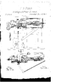
- Figure 1 is a side view of the improved mechanism.
- Figure 2 is a top View of the same.
- My invention consists of a mechanism by which the heads of screws or screw-blanks are turned or shaved, while the jaws and spindle are rapidly revolved, and then nickcd or slotted by being passed across one or more revolving saws, while the spindle is firmly clamped on its axis and prevented from revolving, as before. They then pass back to the first position to remove the burr.
- Y a mechanism by which the heads of screws or screw-blanks are turned or shaved, while the jaws and spindle are rapidly revolved, and then nickcd or slotted by being passed across one or more revolving saws, while the spindle is firmly clamped on its axis and prevented from revolving, as before. They then pass back to the first position to remove the burr.
- A is the spindle, havingjaws at B, operated in the usual manner for receiving and holding the screw-blank.
- the spindle runs in bearings in the sliding frame Y Y, which has a motion up and down on vertical slides attached to the principal frame X X of the machine.
- P is a pulley for giving a rotary motion, by means of a belt passing under it from above, to the spindle A.
- Cvis a clamp, held firmly down upon the pulley P by the spring R is a rest or support, attached to the frame of tho machine, ⁇ upon which the lever Lof the clarnpC rests when the spindle is near its lowest position.
- This cam gives a vertical motion tothe sliding frame YYby means of the adjustable piece N, which rests uponthe working edge of the cam.
- This cam is so constructed that it leaves the spindle at rest, when at its lowest point, long enough for the shaving to be completed. It then raises the sliding frameY Yrapidly, until the screw comes opposite ⁇ the first saw; then it rises slowly, till the saw passes through the head; it then again rises rapidly to the next saw, through which it also passes slowly, and then returns rapidly tothe Arst position.
- G is an adjustable stop for arresting the downward motion of the slide Y and supporting it while the head of the screw is being shaved.
- I'I is a hook for locking the slideY in itslowestl position, and is operated by a pin on the cam M, which unlocksit at the proper moment.
- T is the shaving-tool, and E and F two saws for cutting ⁇ the slot, all of which are attached to the principal frame of the machine by proper contrivanccs.
- the belt passing under the pulley P has also become loose by the raising ofthe pulley, and continues to run freely underv it without causing it to revolve.
- the screw-head now passes slowly past the saw F by the action of the cam M. It then rises rapidly to the other saw E, and passes that slowly, as before.
- the cam then allows the frame Y to descend rapidly to its'iirsbdescribed position.
- the leve; ⁇ L is stopped by the support R, and releases the pulley, which again comes in-contact with the'belt and commences to turn.
- the blank is brought back to its first position in which the head was shaved, and the burr caused bythe saws in cutting the slot is removed by the same tool which performed the shaving, the screw-blank turning upon the same axis and held in the same position in the jaws as before.
- the blank is now thrown out and another inserted, when the preceding operations are repeated.
Landscapes
- Engineering & Computer Science (AREA)
- Mechanical Engineering (AREA)
- Finish Polishing, Edge Sharpening, And Grinding By Specific Grinding Devices (AREA)
Description
Swen/5.
l die] @d wz@ ELIJAH S. PIERCE, OF l HARTFORD, CONNECTICUT. Letters Patent No. 771,908, dated December 10, 1867.
IMPROVEMENT IN MACHINERY FOR SHAVING AND SLOTTING SCREWS.
dt-t Situatie nicht in tlgee Edius haben mit uniting part nt trasmite.
TO ALL WIIOM IT MAY CONCERN:
Beit known that I, ELIJAH S. PIERCE, of Hartford, in the county of Hartford, and State of Connecticut, have invented a new and useful Improvement in Mechanism for Shaving and Slotting Screw-Heads; and I do hereby declare that the following is a full, clear, and exact description of the construction and operation of the same, reference being had to the accompanying drawings, and to the letters of reference marked thereon.
Figure 1 is a side view of the improved mechanism.
Figure 2 is a top View of the same. ll" i My invention consists of a mechanism by which the heads of screws or screw-blanks are turned or shaved, while the jaws and spindle are rapidly revolved, and then nickcd or slotted by being passed across one or more revolving saws, while the spindle is firmly clamped on its axis and prevented from revolving, as before. They then pass back to the first position to remove the burr. Y
A is the spindle, havingjaws at B, operated in the usual manner for receiving and holding the screw-blank. The spindle runs in bearings in the sliding frame Y Y, which has a motion up and down on vertical slides attached to the principal frame X X of the machine. P is a pulley for giving a rotary motion, by means of a belt passing under it from above, to the spindle A. Cvis a clamp, held firmly down upon the pulley P by the spring R is a rest or support, attached to the frame of tho machine,` upon which the lever Lof the clarnpC rests when the spindle is near its lowest position. Mis a cam, attached to a shaft in the frame Xof the machine, to which the improved mechanism is applied. This cam gives a vertical motion tothe sliding frame YYby means of the adjustable piece N, which rests uponthe working edge of the cam. This cam is so constructed that it leaves the spindle at rest, when at its lowest point, long enough for the shaving to be completed. It then raises the sliding frameY Yrapidly, until the screw comes opposite `the first saw; then it rises slowly, till the saw passes through the head; it then again rises rapidly to the next saw, through which it also passes slowly, and then returns rapidly tothe Arst position. G is an adjustable stop for arresting the downward motion of the slide Y and supporting it while the head of the screw is being shaved. I'I is a hook for locking the slideY in itslowestl position, and is operated by a pin on the cam M, which unlocksit at the proper moment. T is the shaving-tool, and E and F two saws for cutting` the slot, all of which are attached to the principal frame of the machine by proper contrivanccs.
The operation of my invention is as follows: When the sliding frameY is at its lowest position, and resting upon the stop G,'it'is not moved by the cam M till the shaving is completed. In this position the clamp C is raised from the pulley P by the lever L resting upoathe support R, and the pullcy is rapidly revolved by a belt passing under it from above. As soon as the shaving is completed the cam M raises the 4frame Y rapidly, till the blank reaches the first saw,y F. The raising of theframc Y has lifted the lever L ofi' from the support R, and the spring S new presses the clamp C down upon the pulley P, holding it firmly in its position and preventing it from turning. The belt passing under the pulley P has also become loose by the raising ofthe pulley, and continues to run freely underv it without causing it to revolve. The screw-head now passes slowly past the saw F by the action of the cam M. It then rises rapidly to the other saw E, and passes that slowly, as before. The cam then allows the frame Y to descend rapidly to its'iirsbdescribed position. The leve;` L is stopped by the support R, and releases the pulley, which again comes in-contact with the'belt and commences to turn. The blank is brought back to its first position in which the head was shaved, and the burr caused bythe saws in cutting the slot is removed by the same tool which performed the shaving, the screw-blank turning upon the same axis and held in the same position in the jaws as before. The blank is now thrown out and another inserted, when the preceding operations are repeated.
v Claim. l What I claim as my invention, and. desire to secure by Letters Patent, is
1. The combination of the cam M, the sliding frame Y, the spindle A, the pulley P, the clamp C, the-spring S, and the rest R, or their equivalents, with a shavingtool, and one or more niclring-saws, substantially'as herein specified.
2'. The combination of the sliding frame Y, the spindle A, and the clampingdevice C, with a shaving-tool and -one or more saws, substantially as described, for thc purpose of shaving, nicking, and barring screw-blanks or other similar articles while held in the same jaws.
l ELIJAII S. PIERCE.
Witnesses SAM. ALLEN, Timo. G. ELLIS.
Publications (1)
| Publication Number | Publication Date |
|---|---|
| US71908A true US71908A (en) | 1867-12-10 |
Family
ID=2141422
Family Applications (1)
| Application Number | Title | Priority Date | Filing Date |
|---|---|---|---|
| US71908D Expired - Lifetime US71908A (en) | Elijah s |
Country Status (1)
| Country | Link |
|---|---|
| US (1) | US71908A (en) |
-
0
- US US71908D patent/US71908A/en not_active Expired - Lifetime
Similar Documents
| Publication | Publication Date | Title |
|---|---|---|
| US71908A (en) | Elijah s | |
| US13354A (en) | Machine for sawing- ra | |
| US68064A (en) | Improvement in milling-tools | |
| US69825A (en) | Self and hosea crane | |
| US109060A (en) | Improvement in scroll-saws | |
| US879793A (en) | Plane. | |
| US88262A (en) | bag ley | |
| US78725A (en) | Luther h | |
| US61503A (en) | Heney d | |
| US10799A (en) | Slitting-gage | |
| US97816A (en) | hokkis peters co | |
| US74982A (en) | Improved planee-ohuck | |
| US76947A (en) | Improvement in oiroulae-saw tables | |
| US95800A (en) | Improvement in machine for wiring blind-rods | |
| US76408A (en) | Improved sole-outtiug machine | |
| US54997A (en) | Improved punching-machine | |
| US13813A (en) | Cutting teeth of gear-wheels | |
| US102160A (en) | John h | |
| US60617A (en) | Waltee d | |
| US48014A (en) | Improved cutter for bread, meat | |
| US78684A (en) | William w | |
| US15196A (en) | Method of ttjknibtg tapering- forms | |
| US15413A (en) | Metal-planer | |
| US13715A (en) | Device for gaging and setting sawmill-dogs | |
| US67190A (en) | Improvement in machine foe tkimming peecussion-caps |