US7158716B2 - Portable pedestal electric heater - Google Patents
Portable pedestal electric heater Download PDFInfo
- Publication number
- US7158716B2 US7158716B2 US10/855,697 US85569704A US7158716B2 US 7158716 B2 US7158716 B2 US 7158716B2 US 85569704 A US85569704 A US 85569704A US 7158716 B2 US7158716 B2 US 7158716B2
- Authority
- US
- United States
- Prior art keywords
- electric heater
- riser
- elongate
- air
- heating element
- Prior art date
- Legal status (The legal status is an assumption and is not a legal conclusion. Google has not performed a legal analysis and makes no representation as to the accuracy of the status listed.)
- Expired - Lifetime
Links
Images


Classifications
-
- F—MECHANICAL ENGINEERING; LIGHTING; HEATING; WEAPONS; BLASTING
- F24—HEATING; RANGES; VENTILATING
- F24H—FLUID HEATERS, e.g. WATER OR AIR HEATERS, HAVING HEAT-GENERATING MEANS, e.g. HEAT PUMPS, IN GENERAL
- F24H9/00—Details
- F24H9/18—Arrangement or mounting of grates or heating means
- F24H9/1854—Arrangement or mounting of grates or heating means for air heaters
- F24H9/1863—Arrangement or mounting of electric heating means
- F24H9/1872—PTC
-
- F—MECHANICAL ENGINEERING; LIGHTING; HEATING; WEAPONS; BLASTING
- F04—POSITIVE - DISPLACEMENT MACHINES FOR LIQUIDS; PUMPS FOR LIQUIDS OR ELASTIC FLUIDS
- F04D—NON-POSITIVE-DISPLACEMENT PUMPS
- F04D17/00—Radial-flow pumps, e.g. centrifugal pumps; Helico-centrifugal pumps
- F04D17/02—Radial-flow pumps, e.g. centrifugal pumps; Helico-centrifugal pumps having non-centrifugal stages, e.g. centripetal
- F04D17/04—Radial-flow pumps, e.g. centrifugal pumps; Helico-centrifugal pumps having non-centrifugal stages, e.g. centripetal of transverse-flow type
-
- F—MECHANICAL ENGINEERING; LIGHTING; HEATING; WEAPONS; BLASTING
- F04—POSITIVE - DISPLACEMENT MACHINES FOR LIQUIDS; PUMPS FOR LIQUIDS OR ELASTIC FLUIDS
- F04D—NON-POSITIVE-DISPLACEMENT PUMPS
- F04D25/00—Pumping installations or systems
- F04D25/02—Units comprising pumps and their driving means
- F04D25/08—Units comprising pumps and their driving means the working fluid being air, e.g. for ventilation
- F04D25/10—Units comprising pumps and their driving means the working fluid being air, e.g. for ventilation the unit having provisions for automatically changing direction of output air
-
- F—MECHANICAL ENGINEERING; LIGHTING; HEATING; WEAPONS; BLASTING
- F24—HEATING; RANGES; VENTILATING
- F24H—FLUID HEATERS, e.g. WATER OR AIR HEATERS, HAVING HEAT-GENERATING MEANS, e.g. HEAT PUMPS, IN GENERAL
- F24H3/00—Air heaters
- F24H3/02—Air heaters with forced circulation
- F24H3/04—Air heaters with forced circulation the air being in direct contact with the heating medium, e.g. electric heating element
- F24H3/0405—Air heaters with forced circulation the air being in direct contact with the heating medium, e.g. electric heating element using electric energy supply, e.g. the heating medium being a resistive element; Heating by direct contact, i.e. with resistive elements, electrodes and fins being bonded together without additional element in-between
- F24H3/0411—Air heaters with forced circulation the air being in direct contact with the heating medium, e.g. electric heating element using electric energy supply, e.g. the heating medium being a resistive element; Heating by direct contact, i.e. with resistive elements, electrodes and fins being bonded together without additional element in-between for domestic or space-heating systems
- F24H3/0417—Air heaters with forced circulation the air being in direct contact with the heating medium, e.g. electric heating element using electric energy supply, e.g. the heating medium being a resistive element; Heating by direct contact, i.e. with resistive elements, electrodes and fins being bonded together without additional element in-between for domestic or space-heating systems portable or mobile
Definitions
- This invention relates generally to heaters. More specifically, the present invention relates to an elongate electric heater elevated above a support surface in which thermal energy is imparted to exhaust air as it passes through a heating element.
- Portable heating devices have been utilized to raise the temperature in a living space for many years.
- Conventional portable forced hot air heaters for consumer use are well-known and are comprised of an electrical heating element and a fan within a housing. Ambient air is forced to pass through or over the heating element thus raising the temperature of the air. As sufficient air passes through the heating element the ambient temperature of the room is raised as desired.
- One type of conventional portable heater is normally low in elevation with respect to a support surface, such as the floor. This low profile increases the distance that the heat must travel (i.e., the heat path) to reach the upper trunk of the users body. The added heat path distance does not produce the desired effect of heating the upper trunk and extremities of the user body efficiently.
- transverse air impeller assembly Another type of conventional heater utilizes a transverse air impeller assembly. This type of heater attempts to raise the exit height of the hot air exhaust stream with respect to the floor.
- transverse air impeller assemblies typically have several sections which must be coupled together by glue or ultrasonic welding. This assembly must then be balanced to insure correct operation. Transverse air impeller assemblies may also necessitate the use of vibration dampers on the motor.
- long transverse air impeller assemblies tend to become misaligned, thereby requiring a special bearing mounted in rubber pads to compensate for the misalignment.
- the above mentioned problems are exacerbated as the length of the transverse air impeller assembly is increased, which limits the elevation that the heated exhaust stream can be raised above the floor with a conventional tower heater design.
- This heating device should have a vertical aspect ratio while using an air generator with an impeller design having the desired air flow characteristics that allow ease of manufacturing and a desirable retail cost for the consumer.
- the present invention is a portable pedestal electric heater apparatus for providing a heated exhaust air stream at an elevation above a support surface.
- the apparatus comprises a tower electric heater and a support riser for supporting the tower electric heater at an elevation above a support surface.
- the tower electric heater comprises an elongate housing having at least one sidewall, a top end, a bottom end, and a longitudinal length extending substantially upward from the bottom end to the top end; and at least one interior space within the elongate housing.
- At least one inlet opening in the elongate housing allows inlet air to enter the at least one interior space.
- An air blower assembly is disposed within the at least one interior space for receiving the inlet air.
- An air outlet opening in the housing allows the exhaust air stream to exit the at least one interior space.
- the support riser comprises a base in contact with the support surface; and at least one riser having a first end and a second end, the first end being connected to the base and the riser extending substantially upward from the first end to the second end, the second end being connected to the bottom end of the elongate housing.
- the support riser has a rise height defined by a distance from where the base contacts the support surface to the second end of the riser.
- An elevation of the heated exhaust air stream is defined by a distance from where the support riser contacts the support surface to a vertical midpoint of the air outlet opening in the housing of the tower electric heater, such that the elevation of the heated exhaust air stream is about 14 inches or greater.
- the air blower assembly further comprises either a centrifugal blower assembly, a transverse blower assembly or an axial fan type blower assembly
- the at least one air impeller further comprises a length and a diameter, and a ratio of the length to the diameter is greater than about 2:1.
- the electric heater further comprises a controller for controlling a function of the portable pedestal electric heater.
- the motor further comprises a variable speed motor having one or more rotational speeds, and the controller controls the rotational speeds.
- the housing rotates or oscillates relative to the support surface, and the rotation or oscillation is about an axis of rotation, the axis of rotation being substantially aligned with a vertical longitudinal axis of the support riser.
- the axis of rotation of the housing is substantially parallel to the axis of rotation of the at least one impeller.
- the axis of rotation of the housing is substantially perpendicular to the axis of rotation of the air impeller.
- the electric heater further comprising a mechanism for rotating or oscillating the housing relative to the support surface with the mechanism being disposed between one of i) the first end of the riser and the base, and ii) the second end of the riser and the housing.
- the heater further comprises a grill covering the air outlet opening with air directing vanes that can be positioned to direct the exhaust air stream exiting the housing to a desired location.
- an overall length of the portable pedestal electric heater is defined by the distance between where the support riser contacts the support surface and the top end of the housing, with the elevation of the heated exhaust air stream being greater than about 65% of the overall length.
- the rise height is greater than about 15% of the overall length.
- the rise height is greater than about 3.5 inches.
- the longitudinal length of the housing is less than about 85% of the overall length.
- the elevation of the heated exhaust air stream is greater than about 70% of the longitudinal length of the housing.
- the rise height is greater than about 25% of the elevation of the heated exhaust air stream.
- the rise height is greater than about 16% of the longitudinal length of the housing.
- the air outlet opening further comprises an elongate air outlet opening in the at least one sidewall and oriented substantially along the longitudinal length of the housing, the elongate air outlet opening allowing the exhaust air to exit the interior space as an elongate exhaust air stream.
- the electric heating element is an elongate electric heating element, the elongate electric heating element being disposed proximate the elongate air outlet opening and oriented substantially along the longitudinal length of the housing, and wherein the elongate electric heating element further comprises a vertical aspect ratio defined by a length of the elongate electric heating element being greater than a width of the elongate electric heating element.
- the vertical aspect ratio of the elongate electric heating element is greater than about 2:1.
- the elongate electric heating element has a length of about 5 inches or greater.
- the elongate electric heating element is a positive temperature coefficient (PTC) heating element capable of producing about 1500 watts of energy.
- PTC positive temperature coefficient
- the electric heater further emits a column of heated exhaust air having a flow pattern that substantially conforms to the vertical aspect ratio of the elongate electric heating element.
- the electric heater further comprising a power cord, where the power cord is routed through a central portion of the support riser and exits at a lower portion of the support riser.
- the support riser comprises an extension of the housing toward the support surface, and wherein the support riser remains assembled to the housing for shipment from a place of manufacturing to a place of sale.
- the electric heater further comprises an axis of rotation about which the elongate housing rotates or oscillates and a longitudinal center axis of the support riser, wherein the axis of rotation and the longitudinal center axis are substantially aligned.
- a portable pedestal electric heater apparatus comprises an operating position, in which the portable pedestal electric heater is assembled and ready for operation, and a non-operating position, in which the portable pedestal electric heater apparatus is disassembled and packaged for shipment.
- the portable pedestal electric heater apparatus comprises a support riser, and a space saving tower electric heater mounted on top of the support riser.
- the portable pedestal electric heater apparatus comprises the space saving tower electric heater being disconnected from the support riser and stored in a package for shipment.
- FIG. 1 is a perspective view of an exemplary embodiment of the portable pedestal electric heater of the present invention
- FIG. 2 is an exploded view of the exemplary embodiment of FIG. 1 ;
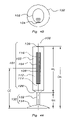
- FIGS. 3A and 3B illustrate the dimensional aspects of exemplary heating elements
- FIGS. 4A and 4B are front and top views, respectively, of an exemplary embodiment of the portable pedestal electric heater illustrating various dimensional relationships of the cooperating elements
- FIG. 5 is a perspective view of another exemplary embodiment of the portable pedestal electric heater with an adjustable height feature
- FIG. 6 is a partial section showing another exemplary embodiment of the portable pedestal electric heater of the present invention.
- FIGS. 7A and 7B illustrate the elevated heated exhaust air stream of a portable pedestal electric heater according to the present invention compared to a conventional heater
- FIGS. 8A , 8 B, 8 C and 8 D are views of exemplary packaging according the present invention.
- FIGS. 9A , 9 B and 9 C are views of yet another exemplary embodiment of the present invention and illustrates exemplary packaging of that embodiment.
- FIGS. 10A , 10 B and 10 C are views of yet another exemplary embodiment of the present invention and illustrates exemplary packaging of that embodiment.
- portable pedestal electric heater 100 includes a tower electric heater 101 and a support riser 130 .
- the tower electric heater 101 includes an elongated housing 102 having a vertical aspect ratio, a heating element or elements 116 , and an air blower assembly 110 for providing a heated exhaust air stream at a height above a support surface.
- the riser support 130 includes a base 134 and a riser 132 for further positioning the heated exhaust air stream at a height above a support surface, thereby allowing the generated heat to more immediately effect a portion of the user's upper body.
- the combination of a tower type electric heater 101 mounted on top of a vertical support riser 130 shortens the heat path between the heating element and an upper portion of the user's body. Since the heat source is further elevated above a support surface and is more closely related to an upper portion of the body, the heat effect to the user is more direct and immediate.
- a tower electric heater 101 in conjunction with a support riser 130 to further elevate the heated exhaust air stream allows for flexibility in design of the individual components of the portable electric heater 100 while also providing for cost efficiency.
- the length of the tower electric heater 101 and the length of the support riser 130 can be manipulated as desired for any particular application in order to obtain the desired heating design characteristics while also minimizing manufacturing cost.
- the desired heating characteristics can be achieved at an elevation above a support surface while still maintaining cost efficiency in, for example, the air blower assembly design and the electric heating element design.
- the pedestal electric heater 100 having a tower electric heater 101 also provides a space saving design over conventional heater and provides for a lower center of gravity thereby improving stability and minimizing the size of the base required to maintain the pedestal electric heater 100 in an upright position and thus avoid tipping of the apparatus.
- housing 102 includes one or more sidewalls 105 extending between a bottom 107 b and a top 107 t thereby defining an interior space 103 .
- Housing 102 includes an elongated construction, preferably extending vertically upward from the bottom 107 b to the top 107 t . This elongate construction of housing 102 results in tower electric heater 101 having a space savings design.
- Housing 102 also includes one or more air inlet openings 108 and an air outlet opening 104 .
- Protective grill 106 is preferably disposed over air outlet 104 for preventing foreign objects from entering the interior space 103 of housing 102 .
- Disposed within interior space 103 is air blower assembly 110 and electric heating element 116 .
- Portable pedestal electric heater also includes support riser 130 having a base 134 and a riser 132 .
- Pedestal electric heater 100 also includes power cord 140 and control assembly 126 . Control assembly 126 controls one or more operations of portable pedestal electric heater 100 .
- FIG. 2 shows an exploded perspective view of portable pedestal electric heater 100 .
- housing 102 may be constructed of more than one component, such as, for example, two halves 102 a , 102 b that are assembled together.
- Housing 102 has at least one air inlet opening 108 and an air outlet opening 104 .
- Air outlet opening 104 may be, for example as shown in FIG. 2 elongate and aligned with the longitudinal length of housing 102 of portable pedestal electric heater 100 .
- Air blower assembly 110 includes at least one motor 114 and at least one air impeller 112 connected to motor 114 .
- Air blower assembly 110 may also include, as in this example, blower housing 113 and other components (not shown).
- the use of air blower assembly 110 preferably allows for the pre-assembly and pre-testing of air blower assembly 110 thereby allowing the manufacture and assembly of portable pedestal electric heater 100 to be less costly when compared to assembling motor 114 , air impeller 112 and blower housing 113 into portable pedestal electric heater 100 as separate components.
- air blower assembly 110 is a centrifugal type blower. It is contemplated that other types of blowers or fans may be used, such as for example, transverse type blowers or axial type fan.
- heating element 116 is disposed within interior space 103 .
- heating element 116 includes an elongate electric heating element that is aligned with the longitudinal length of housing 102 .
- outlet opening 104 also includes an elongate construction and the elongate heating element 116 extends substantially the length of the air outlet opening 104 .
- Use of an elongate electric heating element in conjunction with an elongate outlet opening 104 further allows the heated exhaust air stream to be elevated above a support surface, further facilitating a shorter convection path between the heating element and an upper portion of the user's body.
- an elongated construction for heating element 116 and outlet opening 104 also helps the heated exhaust air stream conform to the general shape of the user's upper body.
- heating element 116 uses a Positive Temperature Coefficient (PTC) type heat generation technology.
- PTC Positive Temperature Coefficient
- the use of a PTC heating element assures a self-regulating low surface temperature of approximately 450 degrees Fahrenheit [232 degrees Celsius].
- the rotation of air impeller 112 causes air to be drawn into housing 102 through air inlet opening(s) 108 .
- the air flow passes through blower assembly 110 , passes through heating element 116 , and exits housing 102 through air outlet opening 104 .
- thermal energy i.e. heat
- protective grill 106 is located proximate air outlet opening 104 .
- Protective grill 106 is preferably designed to minimize it's impedance of the air flow as it exits portable pedestal electric heater 100 while at the same time protecting portable pedestal electric heater 100 from the internal penetration of foreign objects.
- Protective grill 106 may include air directing vanes that can be used to control the direction of the heated exhaust air stream as it exits housing 102 .
- Protective grill 106 may be, for example as shown in FIG. 2 elongate and aligned with the longitudinal length of housing 102 of pedestal electric heater 100 .
- the purpose of the protective grill may include ornamental and/or functional characteristics as described above.
- an intermediate coupler 128 may be used to couple housing 102 to support column 130 .
- a coupler 128 may be either fixed or rotatable.
- housing 102 may be coupled directly to support column 130 such that housing 102 is fixed with respect to support column 130 .
- housing 102 rotates with respect 20 to support column 130 .
- Such rotation may be accomplished either in an oscillatory fashion (over any angular range that may be desired), a stepwise positioning of housing 102 (either manually or under automated control), or in a constant rotation, either in a clockwise or counter-clockwise direction.
- the mechanism for rotation may be located within or below housing 102 and coupled between housing 102 and support riser 130 .
- the rotation mechanism may be located between base 134 and riser 132 of support riser 130 .
- FIG. 2 shows rotation/oscillation mechanism 118 .
- Rotation/oscillation mechanism 118 moves housing 102 of portable pedestal electric heater 100 through rotation and/or oscillation movement. Such movement allows the heated exhaust air stream to be dispersed over a larger coverage area.
- rotation/oscillation mechanism 118 includes a motor 124 , gear 123 , oscillation plate 120 , and oscillation section 122 . It is contemplated that other rotating mechanisms, such as a link and pivot design, may be used to achieve rotation/oscillation movement.
- support riser 130 extends from housing 102 and includes riser 132 and base 134 .
- Support riser 130 may be formed of metal, polymer or other materials.
- Riser 132 maybe comprised of more than one riser member thus allowing for height adjustability (best described with reference to FIG. 5 ).
- the upper portion of riser 132 is connected to coupler 128 or housing 102 and the lower portion of riser 132 is connected to base 134 .
- Base 134 may be comprised of one or multiple pieces attached to one another.
- Base 134 may be made of materials such as metals or polymers or a combination of various materials.
- Base 134 sits on a support surface thus allowing the entire structure of portable pedestal electric heater 100 to be positioned in a substantially vertical, upright and elongate position.
- FIG. 2 illustrates support riser 130 including base 134 and riser 132 as separate pieces
- the invention is not so limited. It is contemplated that the support of housing 102 may be accomplished in a variety of ways, such as forming support riser 130 as a unitary member having a variety of predetermined shapes. Other non-limiting examples of such shapes are shown in FIGS. 9 and 10 .
- the vertical space created by support riser 130 between a support surface and the heated exhaust air stream as it exits housing 102 may be used for other functions, such as for example: mounting controls, humidification, air filtration, etc.
- Portable pedestal electric heater 100 may also include a controller, such as control assembly 126 mounted, for example, on (or in the vicinity of) top 107 t of housing 102 for controlling one or more functions of the device, such as for example, the speed of blower assembly 110 , the rotation or oscillation of the device, power on/off, heat level, etc.
- control assembly 126 may be mounted in oscillation section 122 , a lower portion of housing 102 , on riser 132 or on base 134 .
- control of portable pedestal electric heater 100 may be accomplished by a remote control unit (not shown) in conjunction with or as a replacement for control assembly 126 .
- control assembly 126 on top 107 t of housing 102 on the substantially vertical, upright and elongate structure of portable pedestal electric heater 100 also benefits the user in that the height of the controller above a support surface (floor) allows convenient accessibility for visual inspection and manually adjustment of the controller.
- the exemplary embodiment illustrates one method of routing power cord 140 from an electrical connection (not shown) in portable pedestal electric heater 100 through riser 132 and exiting base 134 at a lower portion of portable pedestal electric heater 100 .
- the routing of power cord 140 through riser 132 prevents power cord 140 from becoming entangled in other components of portable pedestal electric heater 100 during oscillation.
- power cord 140 may exit through an opening in housing 102 .
- FIGS. 3A and 3B show exemplary embodiments of elongate heating element 116 a and 116 b .
- the heat generation method can be, for example, Positive Temperature Coefficient (PTC) heat generation technology.
- elongate heating element 116 a is shown having a predetermined length “L”, in a vertical orientation, a predetermined width “W” and a predetermined depth “D”.
- the ratio of length “L” to width “W” is preferably greater than about 2:1.
- the preferred predetermined length “L” of elongate heating element 116 a is about 8 inches or greater.
- the predetermined length “L” of elongate heating element 116 a is about 5 inches or greater.
- the use of a single elongate heating element minimizes the number of connections and simplifies the design and assembly of the heating element 116 .
- FIG. 3B shows another exemplary embodiment of elongate heating element 116 b .
- elongate heating element 116 b may be constructed of one or more segments 302 a , 302 b , 302 c .
- segments 302 a , 302 b and 302 c are preferably arranged substantially contiguous and aligned end to end.
- the use of multiple segments 302 a , 302 b , 302 c may require additional connections 304 a and 304 b between segments.
- a PTC elongate heating element requires that the length “L” to width “W” aspect ratio be designed to achieve the proper watt density and flow through characteristics.
- the use of a 1500 watt PTC elongate heating element limits length “L” of elongate heating element 116 a or 116 b , in that the watt density within the heating element will not heat the surfaces of heating element 116 a or 116 b efficiently if length “L” is too long.
- This inefficient heating will in turn create inefficient heating of the exhaust air stream.
- This design limitation on the length of the elongate heating element limits the elevation height of a conventional tower heater above a support surface (e.g., floor).
- Support riser 130 allows length “L” of elongate heating element 116 a or 116 b to be of a length so as to maintain the desired watt density while at the same time achieving the desired elevation of the heated exhaust air stream above a support surface. (see FIGS. 4A and 4B ). It is preferred to maintain watt-density as high as possible because as watt-density increases the temperature of the heated exhaust air stream also increases (assuming a constant velocity through the heating element).
- FIGS. 4A and 4B show various dimensional relationships of portable pedestal electric heater 100 .
- dimension HL is the length or height of housing 102 and dimension RH is the length or height of support riser 130 , which in this example is the combined length or height of base 134 and riser 132 .
- Dimension OAL is defined by the length or height of portable pedestal electric heater 100 as measured from the bottom of support riser 130 to top of housing 102 .
- Dimension CE is defined by the distance from the vertical center of air outlet opening 104 to a surface of support riser 130 which contacts a support surface.
- elongate housing 102 of tower electric heater 101 in conjunction with support riser 130 provides flexibility in the design and selection of different components of the device, such as the characteristics and type of air blower assembly 110 or heating element 116 , and also allows the dimensions of elongate housing 102 and support riser 130 to be manipulated to obtain the desired height for optimizing the delivery of the heated exhaust air stream above a support surface. For example, increasing the length or height RH of the support riser 130 allows housing 102 to have a smaller length or height HL, thereby simplifying the design and manufacturing of air blower assembly 110 and heating element 116 . This can save both materials and manufacturing complexity which in turn lowers the cost to the end user.
- rise height RH is greater than about 25% of dimension CE. In addition, in another embodiment rise height RH is greater than about 15% of overall length OAL of portable pedestal electric heater 100 . In yet another embodiment, rise height RH is greater than about 16% of length HL of housing 102 . In another embodiment, length HL of housing 102 is less than about 85% of overall length OAL
- dimension CE is greater than about 65% of overall length OAL. In yet another embodiment dimension CE is greater than about 70% of length HL.
- dimension CE is preferably about 14 inches or greater.
- rise height RH is at least about 3.5 inches or greater and may be adjustable as desired.
- length HL of housing 102 may preferably be between about 14 inches and about 50 inches, while the overall length OAL from the floor to the top of portable pedestal electric heater 100 is preferably about 18 inches or greater, and alternatively between about 18 inches to about 60 inches.
- the above dimensional relationships of portable pedestal electric heater 100 allow for elevating the heated exhaust air stream, thus shortening the heat path and promoting the desired effect on the user.
- These proportional relationships also provide that the length of air impeller 112 will be of a dimension allowing cost effective manufacturing, while yet providing portable pedestal electric heater 100 with the desired vertical elongate aspect ratio.
- the length of air impeller 112 would also require less power to rotate than a longer air impeller, thus allowing motor 114 to use less materials and be more cost effective.
- heating element 116 will have the desired watt density to efficiently heat the exhaust air stream while yet providing the desired vertical elongate aspect ratio and space saving characteristics, best described with respect to FIG. 5 .
- FIG. 5 shows an exemplary embodiment of the portable pedestal electric heater 100 having an adjustable support column 532 .
- adjustable support column 532 includes a plurality of cooperating columns 537 , 538 .
- the cooperating columns include upper column 537 slideably connected to lower column 538 with adjustable coupler 539 there between. In the lower most position, upper column 537 fits substantially within lower column 538 .
- Adjustable coupler 539 allows movement of the columns with respect to one another to adjust the height of support riser 130 and also allows for fixing the columns with respect to one another to set the height of support riser 130 .
- the overall height of portable pedestal electric heater 100 can be adjusted to allow the user more flexibility regarding the elevation of the heated exhaust air stream above floor level. Additional columns and couplers (not shown) may be used as required.
- FIG. 5 also illustrates that the rotational axis of oscillation of housing 102 is preferably substantially co-linear with central axis “A” of portable pedestal electric heater 100 .
- the vertical aspect ratio of housing 102 allows oscillation envelope 510 to be distributed along central axis “A”.
- Oscillation envelope 510 is defined as the area of movement of housing 102 about the rotational axis of oscillation.
- the axis of rotation of air impeller 112 of air blower assembly 110 within interior space 103 of housing 102 is preferably oriented vertically and substantially co-linear with central axis “A” of portable pedestal electric heater 100 . This reduces the effects of gyroscopic precession during the oscillation of housing 102 and increases the stability of portable pedestal electric heater 100 .
- oscillation envelope 510 is substantially equal to a maximum width of a horizontal cross-sectional area of housing 102 .
- the maximum width of a horizontal cross-sectional area of housing 102 is about 12 inches or less.
- the ratio of the length dimension HL of housing 102 to a maximum width of a horizontal cross-sectional area of housing 102 is less than about 1.5:1.
- air impeller 112 has a predetermined diameter and a predetermined length to allow air impeller 112 to have an elongated aspect ratio.
- the predetermined length to the predetermined diameter aspect ratio of impeller 112 is greater than about 2:1. Maintaining the elongated aspect ratio of air impeller 112 allows it to fit within elongate housing 102 of pedestal electric heater 100 .
- air impeller 112 is a limited volume impeller.
- the velocity of the heated exhaust air stream is preferably fixed to effectively reach the user.
- the desired temperature of the heated exhaust air stream is also preferably fixed to deliver an adequate temperature differential between the ambient air temperature and the temperature of the heated exhaust air stream.
- Elongate heating element 116 may be for example a PTC heating element with a fixed maximum wattage of 1500W. This fixed wattage requirement along with the fixed temperature and velocity requirements of the heated exhaust air stream determines a fixed watt density requirement of elongate heating element 116 .
- the fixed watt density requirement of elongate heating element 116 is achieved by the proper ratio of length “L” to width “W” of elongate heating element 116 .
- An effective way to limit volume Q of impeller 112 is to reduce its diameter.
- the limited diameter of impeller 112 also more easily fits within elongate housing 102 of pedestal electric heater 100 , thus maintaining the desired vertical aspect ratio.
- the vertical aspect ratio of housing 102 allows the oscillating components of portable pedestal electric heater 100 to be substantially on center with support riser 530 along central axis “A” thus increasing the stability of portable pedestal electric heater 100 .
- the substantially vertical, upright and elongate structure of portable pedestal electric heater 100 helps to minimizes the vertical distance above a support surface, (floor) to the center of gravity of portable pedestal electric heater 100 .
- This structure along with substantially centering the oscillating components on support riser 530 along central axis “A”, coupled with the reduced effects of gyroscopic precession during oscillation, increase the stability of portable pedestal electric heater 100 .
- This increased stability allows dimension BB of base 134 to be minimized.
- the minimized dimension BB of base 134 allows portable pedestal electric heater 100 to have further space saving characteristics and, to be easily transported from place to place within a living space or between various living spaces as desired.
- the minimized dimension BB of base 134 also allows an economization of the size of a shipping package for portable pedestal electric heater 100 .
- the economization of the size of a shipping package allows more units to be shipped in a container, (i.e. truck) and thereby reduces the overall cost per unit of transportation, (see FIGS. 8A , 8 B and 8 C).
- Dimension BB of base 134 is equal to the maximum width of a horizontal cross-sectional area of base 134 .
- dimension BB of base 134 is about 18 inches or less for a portable pedestal electric heater 100 having housing 102 with a maximum width of a horizontal cross-sectional area of about 12 inches or less.
- the maximum width of a horizontal cross-sectional area of housing 102 is less than about 70% of dimension BB.
- FIG. 6 shows another exemplary embodiment of the portable pedestal electric heater.
- FIG. 6 illustrates a partial cross sectional side view through portable pedestal electric heater 600 .
- Portable pedestal electric heater 600 is comprised of housing 102 defining interior space 603 .
- Heating element 116 and blower assembly 610 Within interior space 603 is disposed heating element 116 and blower assembly 610 .
- Blower assembly 610 in this example, includes motor 614 , air impeller 612 and blower housing 613 .
- air impeller 612 is a centrifugal blower type impeller.
- Air 644 is drawn into blower assembly 610 through at least one inlet opening 108 in housing 102 .
- Exhaust air 645 is discharged from blower assembly 610 into interior space 603 of housing 102 .
- Exhaust air 645 then passes through elongate heating element 116 and is discharged from portable pedestal electric heater 600 as heated exhaust air stream 640 .
- Heating element 116 is located proximate air exit opening 104 .
- Also located proximate air exit opening 104 is protective grill 106 .
- blower assembly 610 in the lower portion of housing 102 lowers the center of gravity of portable pedestal electric heater 600 in that the weight of motor 614 , impeller 612 and blower housing 613 are low with respect to the bottom of support riser 130 . This increases the stability of portable pedestal electric heater 600 and allows for the desired vertical elongate aspect ratio, increased height of the heated exhaust air stream, and space saving characteristics.
- FIGS. 7A and 7B illustrate the advantages of the pedestal electric heater of the present invention when compared to a standard portable electric heater design.
- FIG. 7A shows an exemplary embodiment of the present invention and
- FIG. 7B illustrates standard portable electric heater 700 .
- heated exhaust air stream 742 exits standard portable electric heater 700 at a low elevation. This low elevation increases the distance that the heat must traverse to reach an upper portion of user 701 .
- FIG. 7A illustrates the improved performance characteristics of portable pedestal electric heater 100 in accordance with the present invention.
- Heated exhaust air steam 740 exits portable pedestal electric heater 100 at an elevation that shortens the distance that must be traversed by heated exhaust air stream 740 in order to effect an upper potion of user 701 .
- the upper portion of user 701 is normally more exposed and therefore will experience the effects of heated exhaust air stream 740 more readily, contributing to the more immediate relief of user 701 .
- the substantially vertical, upright and elongate structure of portable pedestal electric heater 100 also benefits user 701 in that the shape of heated exhaust air stream 740 may be elongate and vertical as it exits housing 102 .
- An elongate and vertical shape of heated exhaust air stream 740 generally conforms to the human body.
- FIGS. 8A , 8 B, 8 C, and 8 D illustrate another advantage realized with respect to packaging and shipment of the exemplary design of the portable pedestal electric heater 100 of the present invention.
- portable pedestal electric heater 100 is packaged in a non-operating configuration, wherein housing 102 is separated from riser 132 and base 134 .
- base 134 is designed to be separate from riser 132 and further disassemble into one or more portions, such as portions 134 a and 134 b .
- Shipping box 802 is therefore able to economize the space necessary to transport portable pedestal electric heater 100 , thus using less packaging materials and lowering the cost of the packaging.
- packaging of the portable pedestal electric heater 100 of the present invention on pallet 804 and in container 806 is also economized. Furthermore, the number of units capable of transportation in shipping container 806 as shown in FIG. 8D is maximized.
- FIG. 9A shows yet another exemplary embodiment of portable pedestal electric heater 900 with support riser 930 .
- Support riser 930 can be a unitary part or constructed of more than one piece assembled together.
- Support riser 930 achieves the designed dimension CE as defined by the distance from the vertical center of outlet opening 104 to the bottom of support riser 930 and the stability that support riser 130 , (comprised of riser 132 and base 134 ) achieved in previously described embodiments.
- FIGS. 9B and 9C illustrate the packaging of portable pedestal electric heater 900 in a non-operating configuration, wherein housing 102 is separated from support riser 930 . In this example housing 102 has the ability to fit within support riser 930 . Shipping box 902 is therefore able to economize the space necessary to transport portable pedestal electric heater 900 , thus using less packaging materials and lowering the cost of the packaging.
- FIG. 10A shows yet another exemplary embodiment of portable pedestal electric heater 1000 with support riser 1030 .
- Support riser 1030 in this example is comprised of support column 1032 and base 1034 .
- Support column 1032 may be a unitary part of housing 102 or a separate part assembled to housing 102 .
- Support riser 1030 achieves the designed dimension CE as defined by the distance from the vertical center of outlet opening 104 to the bottom of support riser 1030 and the stability that support riser 130 , (comprised of riser 132 and base 134 ) achieved in previously described embodiments.
- FIGS. 10B and 10C illustrate the packaging of portable pedestal electric heater 1000 in a non-operating configuration, wherein base 1034 is separated from support column 1032 .
- housing 102 and support column 1032 are shipped to a customer as a unitary part or assembled together.
- shipping box 1002 does not economize space as well as previous examples, it does require less assembly for the end user.
Priority Applications (3)
| Application Number | Priority Date | Filing Date | Title |
|---|---|---|---|
| US10/855,697 US7158716B2 (en) | 2002-12-18 | 2004-05-27 | Portable pedestal electric heater |
| PCT/US2004/019803 WO2005057091A1 (fr) | 2003-11-19 | 2004-06-21 | Appareil de chauffage electrique a air pulse sur socle |
| US11/617,141 US20070209701A1 (en) | 2002-12-18 | 2006-12-28 | Portable pedestal air filtering device |
Applications Claiming Priority (6)
| Application Number | Priority Date | Filing Date | Title |
|---|---|---|---|
| US10/322,169 US6760543B1 (en) | 2002-12-18 | 2002-12-18 | Heated air circulator with uniform exhaust airflow |
| US10/347,079 US20040120815A1 (en) | 2002-12-18 | 2003-01-17 | Cooling fan |
| US10/431,964 US6942456B2 (en) | 2002-12-18 | 2003-05-08 | Home comfort appliance |
| US52336903P | 2003-11-19 | 2003-11-19 | |
| US10/720,374 US6997680B2 (en) | 2002-12-18 | 2003-11-24 | Home comfort device |
| US10/855,697 US7158716B2 (en) | 2002-12-18 | 2004-05-27 | Portable pedestal electric heater |
Related Parent Applications (1)
| Application Number | Title | Priority Date | Filing Date |
|---|---|---|---|
| US10/720,374 Continuation-In-Part US6997680B2 (en) | 2002-12-18 | 2003-11-24 | Home comfort device |
Related Child Applications (1)
| Application Number | Title | Priority Date | Filing Date |
|---|---|---|---|
| US11/617,141 Continuation-In-Part US20070209701A1 (en) | 2002-12-18 | 2006-12-28 | Portable pedestal air filtering device |
Publications (2)
| Publication Number | Publication Date |
|---|---|
| US20040218912A1 US20040218912A1 (en) | 2004-11-04 |
| US7158716B2 true US7158716B2 (en) | 2007-01-02 |
Family
ID=34681457
Family Applications (1)
| Application Number | Title | Priority Date | Filing Date |
|---|---|---|---|
| US10/855,697 Expired - Lifetime US7158716B2 (en) | 2002-12-18 | 2004-05-27 | Portable pedestal electric heater |
Country Status (2)
| Country | Link |
|---|---|
| US (1) | US7158716B2 (fr) |
| WO (1) | WO2005057091A1 (fr) |
Cited By (31)
| Publication number | Priority date | Publication date | Assignee | Title |
|---|---|---|---|---|
| US20070209701A1 (en) * | 2002-12-18 | 2007-09-13 | Lasko Holdings, Inc. | Portable pedestal air filtering device |
| US20070267536A1 (en) * | 2005-05-27 | 2007-11-22 | Hill Herbert A | Method and apparatus for pre-heating an aircraft engine |
| US20070297773A1 (en) * | 2006-06-22 | 2007-12-27 | Tianyu Gao | Fan heater |
| US20110056928A1 (en) * | 2009-09-08 | 2011-03-10 | Tsinghua University | Wall mounted electric heater |
| US20110056929A1 (en) * | 2009-09-08 | 2011-03-10 | Tsinghua University | Electric heater |
| US20120183283A1 (en) * | 2011-01-18 | 2012-07-19 | Peet Blair G | Air dehumidifier system for enclosures and safes |
| US20130251353A1 (en) * | 2012-03-21 | 2013-09-26 | Bruce Amberson | Heater |
| DE102013001441A1 (de) * | 2013-01-29 | 2014-07-31 | Esw Gmbh | Heizungsanordnung zum Aufheizen eines die Heizungsanordnung durchströmenden Mediums |
| US20150093098A1 (en) * | 2009-03-04 | 2015-04-02 | Dyson Technology Limited | Fan assembly |
| US20150354586A1 (en) * | 2009-03-04 | 2015-12-10 | Dyson Technology Limited | Fan assembly |
| USD761733S1 (en) | 2014-09-12 | 2016-07-19 | Steelcase Inc. | Electrical hub |
| US20160209078A1 (en) * | 2015-01-15 | 2016-07-21 | Stylianos Giannoulis | Heating device |
| USD762177S1 (en) | 2014-09-12 | 2016-07-26 | Steelcase Inc. | Electrical hub |
| USD778417S1 (en) * | 2014-12-15 | 2017-02-07 | Samsung Electronics Co., Ltd. | Air conditioner |
| US20170122604A1 (en) * | 2015-10-28 | 2017-05-04 | Jinhua City Xin'an Electric Co., Ltd | Constant temperature and humidity machine |
| USD790676S1 (en) * | 2015-07-31 | 2017-06-27 | Samsung Electronics Co., Ltd. | Air conditioner |
| USD791293S1 (en) * | 2015-07-31 | 2017-07-04 | Samsung Electronics Co., Ltd. | Air conditioner |
| USD791291S1 (en) * | 2015-07-31 | 2017-07-04 | Samsung Electronics Co., Ltd. | Air conditioner |
| USD791292S1 (en) * | 2015-07-31 | 2017-07-04 | Samsung Electronics Co., Ltd. | Air conditioner |
| US20170284701A1 (en) * | 2016-03-31 | 2017-10-05 | Gd Midea Environment Appliances Mfg Co., Ltd. | Electric radiator |
| US20170343240A1 (en) * | 2016-05-30 | 2017-11-30 | Steven Yu | Combination cooling and heating fan structure |
| US10333284B2 (en) | 2014-09-12 | 2019-06-25 | Steelcase Inc. | Floor power distribution system |
| US10385867B2 (en) | 2016-07-19 | 2019-08-20 | Jinhua City Xin'an Electric Co., Ltd. | Multi-directional cooling fan |
| US10582815B1 (en) * | 2017-09-12 | 2020-03-10 | Randy Josey | Body air dryer for a bathing stall |
| US10945569B1 (en) * | 2018-05-21 | 2021-03-16 | Sibu Varghese | Body dryer system and method of use |
| US20210302068A1 (en) * | 2020-03-31 | 2021-09-30 | World & Main (Cranbury) LLC | PTC Heater with Energy Save Function |
| US20210302065A1 (en) * | 2020-03-31 | 2021-09-30 | World & Main (Cranbury) LLC | Segmented PTC Heating Element Array |
| US11156225B2 (en) * | 2017-09-01 | 2021-10-26 | Lg Electronics Inc. | Flow generating device |
| USD937401S1 (en) | 2020-05-11 | 2021-11-30 | E2 Limited | Tower fan |
| USD945590S1 (en) | 2019-05-23 | 2022-03-08 | E2 Limited | Tower fan |
| US11739760B2 (en) * | 2020-06-02 | 2023-08-29 | Lg Electronics Inc. | Blower |
Families Citing this family (69)
| Publication number | Priority date | Publication date | Assignee | Title |
|---|---|---|---|---|
| JP2004162963A (ja) * | 2002-11-12 | 2004-06-10 | Sumitomo Electric Ind Ltd | ガス加熱方法及び加熱装置 |
| US6760543B1 (en) * | 2002-12-18 | 2004-07-06 | Lasko Holdings, Inc. | Heated air circulator with uniform exhaust airflow |
| IL169459A (en) * | 2005-06-29 | 2009-11-18 | Starsun Platinum Ltd | Reflection heating fan |
| GB0814835D0 (en) | 2007-09-04 | 2008-09-17 | Dyson Technology Ltd | A Fan |
| US7814677B2 (en) * | 2007-12-07 | 2010-10-19 | Brewer Howard W | Dryer extension and method of drying an object |
| GB2464736A (en) | 2008-10-25 | 2010-04-28 | Dyson Technology Ltd | Fan with a filter |
| GB2476172B (en) | 2009-03-04 | 2011-11-16 | Dyson Technology Ltd | Tilting fan stand |
| AU2012200112B2 (en) * | 2009-03-04 | 2012-11-29 | Dyson Technology Limited | A fan assembly |
| WO2011044305A1 (fr) * | 2009-10-07 | 2011-04-14 | The Procter & Gamble Company | Composition détergente |
| GB0919473D0 (en) | 2009-11-06 | 2009-12-23 | Dyson Technology Ltd | A fan |
| GB2478927B (en) | 2010-03-23 | 2016-09-14 | Dyson Technology Ltd | Portable fan with filter unit |
| WO2011147318A1 (fr) | 2010-05-27 | 2011-12-01 | Li Dezheng | Dispositif pour souffler de l'air au moyen d'un ensemble buse à fente étroite |
| GB2482547A (en) | 2010-08-06 | 2012-02-08 | Dyson Technology Ltd | A fan assembly with a heater |
| GB2483448B (en) | 2010-09-07 | 2015-12-02 | Dyson Technology Ltd | A fan |
| JP5588565B2 (ja) | 2010-10-13 | 2014-09-10 | ダイソン テクノロジー リミテッド | 送風機組立体 |
| ES2619373T3 (es) | 2010-10-18 | 2017-06-26 | Dyson Technology Limited | Conjunto de ventilador |
| GB2484670B (en) | 2010-10-18 | 2018-04-25 | Dyson Technology Ltd | A fan assembly |
| WO2012059730A1 (fr) | 2010-11-02 | 2012-05-10 | Dyson Technology Limited | Ensemble ventilateur |
| GB2486019B (en) | 2010-12-02 | 2013-02-20 | Dyson Technology Ltd | A fan |
| CN102226577B (zh) * | 2011-05-23 | 2014-06-04 | 深圳市顺章电器有限公司 | 发热体后置的暖风机 |
| BR112014001474A2 (pt) | 2011-07-27 | 2017-02-21 | Dyson Technology Ltd | conjunto de ventilador |
| GB2493506B (en) | 2011-07-27 | 2013-09-11 | Dyson Technology Ltd | A fan assembly |
| GB201119500D0 (en) | 2011-11-11 | 2011-12-21 | Dyson Technology Ltd | A fan assembly |
| GB2496877B (en) | 2011-11-24 | 2014-05-07 | Dyson Technology Ltd | A fan assembly |
| GB2498547B (en) | 2012-01-19 | 2015-02-18 | Dyson Technology Ltd | A fan |
| GB2499044B (en) | 2012-02-06 | 2014-03-19 | Dyson Technology Ltd | A fan |
| GB2499042A (en) | 2012-02-06 | 2013-08-07 | Dyson Technology Ltd | A nozzle for a fan assembly |
| GB2499041A (en) | 2012-02-06 | 2013-08-07 | Dyson Technology Ltd | Bladeless fan including an ionizer |
| GB2500017B (en) | 2012-03-06 | 2015-07-29 | Dyson Technology Ltd | A Humidifying Apparatus |
| GB2500012B (en) | 2012-03-06 | 2016-07-06 | Dyson Technology Ltd | A Humidifying Apparatus |
| GB2512192B (en) | 2012-03-06 | 2015-08-05 | Dyson Technology Ltd | A Humidifying Apparatus |
| MY167968A (en) | 2012-03-06 | 2018-10-09 | Dyson Technology Ltd | A fan assembly |
| GB2500011B (en) | 2012-03-06 | 2016-07-06 | Dyson Technology Ltd | A Humidifying Apparatus |
| GB2500010B (en) | 2012-03-06 | 2016-08-24 | Dyson Technology Ltd | A humidifying apparatus |
| US20130248510A1 (en) * | 2012-03-26 | 2013-09-26 | Binggang Weng | Electric heater capable of automatic heating |
| GB2500903B (en) | 2012-04-04 | 2015-06-24 | Dyson Technology Ltd | Heating apparatus |
| GB2501301B (en) | 2012-04-19 | 2016-02-03 | Dyson Technology Ltd | A fan assembly |
| USD744623S1 (en) * | 2012-05-02 | 2015-12-01 | Jianhua Ren | Electric heater |
| GB2518935B (en) | 2012-05-16 | 2016-01-27 | Dyson Technology Ltd | A fan |
| GB2502104B (en) | 2012-05-16 | 2016-01-27 | Dyson Technology Ltd | A fan |
| WO2013171452A2 (fr) | 2012-05-16 | 2013-11-21 | Dyson Technology Limited | Ventilateur |
| GB2503907B (en) | 2012-07-11 | 2014-05-28 | Dyson Technology Ltd | A fan assembly |
| EP2732995B2 (fr) * | 2012-11-15 | 2018-03-21 | Eberspächer catem GmbH & Co. KG | Chauffage électrique pour véhicule automobile |
| US9395100B2 (en) * | 2012-12-06 | 2016-07-19 | Twin-Star International, Inc. | Low air resistance infrared heating system and method |
| AU350179S (en) | 2013-01-18 | 2013-08-15 | Dyson Technology Ltd | Humidifier or fan |
| BR302013003358S1 (pt) | 2013-01-18 | 2014-11-25 | Dyson Technology Ltd | Configuração aplicada em umidificador |
| AU350181S (en) | 2013-01-18 | 2013-08-15 | Dyson Technology Ltd | Humidifier or fan |
| AU350140S (en) | 2013-01-18 | 2013-08-13 | Dyson Technology Ltd | Humidifier or fan |
| GB2510195B (en) | 2013-01-29 | 2016-04-27 | Dyson Technology Ltd | A fan assembly |
| RU2684043C2 (ru) | 2013-01-29 | 2019-04-03 | Дайсон Текнолоджи Лимитед | Вентилятор в сборе |
| CA152658S (en) | 2013-03-07 | 2014-05-20 | Dyson Technology Ltd | Fan |
| CA152657S (en) | 2013-03-07 | 2014-05-20 | Dyson Technology Ltd | Fan |
| CA152655S (en) | 2013-03-07 | 2014-05-20 | Dyson Technology Ltd | Fan |
| BR302013004394S1 (pt) | 2013-03-07 | 2014-12-02 | Dyson Technology Ltd | Configuração aplicada a ventilador |
| USD729372S1 (en) | 2013-03-07 | 2015-05-12 | Dyson Technology Limited | Fan |
| CA152656S (en) | 2013-03-07 | 2014-05-20 | Dyson Technology Ltd | Fan |
| GB2516058B (en) | 2013-07-09 | 2016-12-21 | Dyson Technology Ltd | A fan assembly with an oscillation and tilt mechanism |
| CA154722S (en) | 2013-08-01 | 2015-02-16 | Dyson Technology Ltd | Fan |
| TWD172707S (zh) | 2013-08-01 | 2015-12-21 | 戴森科技有限公司 | 風扇 |
| CA154723S (en) | 2013-08-01 | 2015-02-16 | Dyson Technology Ltd | Fan |
| GB2518638B (en) | 2013-09-26 | 2016-10-12 | Dyson Technology Ltd | Humidifying apparatus |
| CN103759319B (zh) * | 2014-01-17 | 2016-04-27 | 江苏佳得顺热能设备有限公司 | 两用取暖器 |
| GB2528709B (en) | 2014-07-29 | 2017-02-08 | Dyson Technology Ltd | Humidifying apparatus |
| GB2528708B (en) | 2014-07-29 | 2016-06-29 | Dyson Technology Ltd | A fan assembly |
| GB2528704A (en) | 2014-07-29 | 2016-02-03 | Dyson Technology Ltd | Humidifying apparatus |
| USD870870S1 (en) | 2016-07-25 | 2019-12-24 | Electrolux Appliances Aktiebolag | Air conditioner |
| IT201700112238A1 (it) * | 2017-10-28 | 2019-04-28 | Mauro Romagnuolo | Colonna multifunzione per il riscaldamento |
| USD1017786S1 (en) * | 2023-03-07 | 2024-03-12 | Shenzhen Qianyan Technology LTD | Fan heater |
| USD1017787S1 (en) * | 2023-04-14 | 2024-03-12 | Shenzhen Qianyan Technology LTD | Heater |
Citations (44)
| Publication number | Priority date | Publication date | Assignee | Title |
|---|---|---|---|---|
| US1429130A (en) | 1921-07-09 | 1922-09-12 | Lfred E Dutton | Heating device |
| GB265279A (en) | 1925-11-02 | 1927-02-02 | Oliver Leopold Peard | Improvements in or relating to electric heaters |
| US2255759A (en) | 1940-04-24 | 1941-09-16 | Howard H Carpenter | Electric heating appliance |
| US2375920A (en) * | 1939-01-14 | 1945-05-15 | Elmer S Hewitt | Electric drier |
| US2471784A (en) | 1945-11-19 | 1949-05-31 | Seifner | Heat exchange unit |
| FR993168A (fr) | 1949-06-09 | 1951-10-29 | Radiateur électrique | |
| DE863112C (de) | 1949-12-31 | 1953-01-15 | Kaeser Anton Fa | Elektrisches Raumheizgeraet |
| US2824429A (en) | 1955-06-08 | 1958-02-25 | Mitchell Mfg Company | Means for circulating and distributing air |
| US3085350A (en) * | 1960-12-01 | 1963-04-16 | Westinghouse Electric Corp | Portable heater |
| US3175550A (en) | 1963-02-25 | 1965-03-30 | Knapp Monarch Co | Dual air heater |
| US3251540A (en) | 1963-12-17 | 1966-05-17 | Lau Blower Co | Air moving device |
| GB1037098A (en) | 1963-09-03 | 1966-07-27 | Esge Exp Ag | Hot-air blower |
| US3267255A (en) | 1964-01-30 | 1966-08-16 | Gen Electric | Forced air electric baseboard heater |
| US3290112A (en) | 1965-03-09 | 1966-12-06 | Hagen B Gillenwater | Apparatus for dispensing insecticides |
| FR1502108A (fr) | 1966-10-07 | 1967-11-18 | Alarme Et Telesurveillance A T | Dispositif de déclenchement d'alarme |
| US3575582A (en) * | 1968-08-27 | 1971-04-20 | Darrell W Covault | Electric furnace |
| US3643346A (en) * | 1969-05-29 | 1972-02-22 | Lestron International Corp | Drying apparatus |
| FR2136153A5 (fr) * | 1971-04-05 | 1972-12-22 | Konstandt Francisco | |
| US3725640A (en) | 1971-06-21 | 1973-04-03 | Gen Electric | Electric fan heater |
| GB2037418A (en) | 1978-11-20 | 1980-07-09 | Nunez H | An improved heater fan |
| EP0072663A1 (fr) | 1981-08-17 | 1983-02-23 | Kemtron International (Holdings) Limited | Ventilateur polyvalent |
| DE3200217A1 (de) * | 1982-01-07 | 1983-07-14 | Petz Electro, 3185 Schmitten | Einrichtung zum erzeugen von warmluftstroemungen |
| JPS61243254A (ja) * | 1985-04-19 | 1986-10-29 | Matsushita Seiko Co Ltd | 送風装置付縦型電気スト−ブ |
| US4703152A (en) * | 1985-12-11 | 1987-10-27 | Holmes Products Corp. | Tiltable and adjustably oscillatable portable electric heater/fan |
| US4743739A (en) | 1986-02-20 | 1988-05-10 | Tateishi Arthur K | Oscillating louver electric fan heater |
| US4780595A (en) * | 1987-08-28 | 1988-10-25 | Alban Richard F | Body dryer |
| US4900898A (en) | 1988-01-20 | 1990-02-13 | Kling William E | Electric space heater |
| EP0417309A1 (fr) | 1989-03-15 | 1991-03-20 | Inax Corporation | Regulateur de radiateur soufflant |
| US5083011A (en) | 1990-11-27 | 1992-01-21 | Coppus Engineering Corporation | Air heater with safety control circuit |
| JPH0484069A (ja) * | 1990-07-25 | 1992-03-17 | Matsushita Electric Ind Co Ltd | スタンド付き電気温風機 |
| US5192853A (en) * | 1991-10-22 | 1993-03-09 | Yeh Yuan Chang | Heating set having positive temperatue coefficient thermistor elements adhesively connected to heat radiator devices |
| EP0745814A2 (fr) | 1995-05-30 | 1996-12-04 | Duracraft Corporation | Appareil de chauffage électrique ajustable |
| US6079949A (en) | 1998-11-13 | 2000-06-27 | Lasko Holdings, Inc. | Ratchet assembly for pedestal fan |
| US6321034B2 (en) * | 1999-12-06 | 2001-11-20 | The Holmes Group, Inc. | Pivotable heater |
| USRE37642E1 (en) * | 1994-06-08 | 2002-04-09 | The Holmes Group, Inc. | Air heater with angled PTC heaters producing diverging heated airflow |
| US6480672B1 (en) * | 2001-03-07 | 2002-11-12 | Holmes Group, Inc. | Flat panel heater |
| USD468005S1 (en) * | 2002-01-04 | 2002-12-31 | Verdell L Bailey | Space heater with remote control |
| WO2003009735A1 (fr) * | 2001-07-26 | 2003-02-06 | Kalotihos, Spiros | Sechoir pour le corps |
| US20030128971A1 (en) | 2002-01-10 | 2003-07-10 | Birdsell Walter G. | Portable electric heater |
| WO2003078846A1 (fr) | 2002-03-18 | 2003-09-25 | Tadashi Sato | Ventilateur pouvant également servir de chauffage |
| USD481783S1 (en) * | 2002-05-16 | 2003-11-04 | Su-Tim Fok | Warm-or-cool electric fan |
| USD483457S1 (en) * | 2002-12-23 | 2003-12-09 | Pierce Wang | Fan heater |
| US6760543B1 (en) * | 2002-12-18 | 2004-07-06 | Lasko Holdings, Inc. | Heated air circulator with uniform exhaust airflow |
| US6842581B2 (en) * | 2003-04-28 | 2005-01-11 | Neil Schafer | Body drier with interconnected cylindrical air blower housings |
-
2004
- 2004-05-27 US US10/855,697 patent/US7158716B2/en not_active Expired - Lifetime
- 2004-06-21 WO PCT/US2004/019803 patent/WO2005057091A1/fr active Application Filing
Patent Citations (46)
| Publication number | Priority date | Publication date | Assignee | Title |
|---|---|---|---|---|
| US1429130A (en) | 1921-07-09 | 1922-09-12 | Lfred E Dutton | Heating device |
| GB265279A (en) | 1925-11-02 | 1927-02-02 | Oliver Leopold Peard | Improvements in or relating to electric heaters |
| US2375920A (en) * | 1939-01-14 | 1945-05-15 | Elmer S Hewitt | Electric drier |
| US2255759A (en) | 1940-04-24 | 1941-09-16 | Howard H Carpenter | Electric heating appliance |
| US2471784A (en) | 1945-11-19 | 1949-05-31 | Seifner | Heat exchange unit |
| FR993168A (fr) | 1949-06-09 | 1951-10-29 | Radiateur électrique | |
| DE863112C (de) | 1949-12-31 | 1953-01-15 | Kaeser Anton Fa | Elektrisches Raumheizgeraet |
| US2824429A (en) | 1955-06-08 | 1958-02-25 | Mitchell Mfg Company | Means for circulating and distributing air |
| US3085350A (en) * | 1960-12-01 | 1963-04-16 | Westinghouse Electric Corp | Portable heater |
| US3175550A (en) | 1963-02-25 | 1965-03-30 | Knapp Monarch Co | Dual air heater |
| GB1037098A (en) | 1963-09-03 | 1966-07-27 | Esge Exp Ag | Hot-air blower |
| US3251540A (en) | 1963-12-17 | 1966-05-17 | Lau Blower Co | Air moving device |
| US3267255A (en) | 1964-01-30 | 1966-08-16 | Gen Electric | Forced air electric baseboard heater |
| US3290112A (en) | 1965-03-09 | 1966-12-06 | Hagen B Gillenwater | Apparatus for dispensing insecticides |
| FR1502108A (fr) | 1966-10-07 | 1967-11-18 | Alarme Et Telesurveillance A T | Dispositif de déclenchement d'alarme |
| US3575582A (en) * | 1968-08-27 | 1971-04-20 | Darrell W Covault | Electric furnace |
| US3643346A (en) * | 1969-05-29 | 1972-02-22 | Lestron International Corp | Drying apparatus |
| FR2136153A5 (fr) * | 1971-04-05 | 1972-12-22 | Konstandt Francisco | |
| US3725640A (en) | 1971-06-21 | 1973-04-03 | Gen Electric | Electric fan heater |
| GB2037418A (en) | 1978-11-20 | 1980-07-09 | Nunez H | An improved heater fan |
| EP0072663A1 (fr) | 1981-08-17 | 1983-02-23 | Kemtron International (Holdings) Limited | Ventilateur polyvalent |
| DE3200217A1 (de) * | 1982-01-07 | 1983-07-14 | Petz Electro, 3185 Schmitten | Einrichtung zum erzeugen von warmluftstroemungen |
| JPS61243254A (ja) * | 1985-04-19 | 1986-10-29 | Matsushita Seiko Co Ltd | 送風装置付縦型電気スト−ブ |
| US4703152A (en) * | 1985-12-11 | 1987-10-27 | Holmes Products Corp. | Tiltable and adjustably oscillatable portable electric heater/fan |
| US4743739A (en) | 1986-02-20 | 1988-05-10 | Tateishi Arthur K | Oscillating louver electric fan heater |
| US4780595A (en) * | 1987-08-28 | 1988-10-25 | Alban Richard F | Body dryer |
| US4900898A (en) | 1988-01-20 | 1990-02-13 | Kling William E | Electric space heater |
| EP0417309A1 (fr) | 1989-03-15 | 1991-03-20 | Inax Corporation | Regulateur de radiateur soufflant |
| JPH0484069A (ja) * | 1990-07-25 | 1992-03-17 | Matsushita Electric Ind Co Ltd | スタンド付き電気温風機 |
| US5083011A (en) | 1990-11-27 | 1992-01-21 | Coppus Engineering Corporation | Air heater with safety control circuit |
| US5192853A (en) * | 1991-10-22 | 1993-03-09 | Yeh Yuan Chang | Heating set having positive temperatue coefficient thermistor elements adhesively connected to heat radiator devices |
| USRE37642E1 (en) * | 1994-06-08 | 2002-04-09 | The Holmes Group, Inc. | Air heater with angled PTC heaters producing diverging heated airflow |
| EP0745814A2 (fr) | 1995-05-30 | 1996-12-04 | Duracraft Corporation | Appareil de chauffage électrique ajustable |
| US6079949A (en) | 1998-11-13 | 2000-06-27 | Lasko Holdings, Inc. | Ratchet assembly for pedestal fan |
| US6321034B2 (en) * | 1999-12-06 | 2001-11-20 | The Holmes Group, Inc. | Pivotable heater |
| US6480672B1 (en) * | 2001-03-07 | 2002-11-12 | Holmes Group, Inc. | Flat panel heater |
| WO2003009735A1 (fr) * | 2001-07-26 | 2003-02-06 | Kalotihos, Spiros | Sechoir pour le corps |
| USD468005S1 (en) * | 2002-01-04 | 2002-12-31 | Verdell L Bailey | Space heater with remote control |
| US20030128971A1 (en) | 2002-01-10 | 2003-07-10 | Birdsell Walter G. | Portable electric heater |
| WO2003078846A1 (fr) | 2002-03-18 | 2003-09-25 | Tadashi Sato | Ventilateur pouvant également servir de chauffage |
| USD481783S1 (en) * | 2002-05-16 | 2003-11-04 | Su-Tim Fok | Warm-or-cool electric fan |
| US6760543B1 (en) * | 2002-12-18 | 2004-07-06 | Lasko Holdings, Inc. | Heated air circulator with uniform exhaust airflow |
| US20040197091A1 (en) * | 2002-12-18 | 2004-10-07 | Orr Paul W. | Electric heater |
| US6973260B2 (en) * | 2002-12-18 | 2005-12-06 | Lasko Holdings, Inc. | Portable electric heater with vertical heated air outlet |
| USD483457S1 (en) * | 2002-12-23 | 2003-12-09 | Pierce Wang | Fan heater |
| US6842581B2 (en) * | 2003-04-28 | 2005-01-11 | Neil Schafer | Body drier with interconnected cylindrical air blower housings |
Non-Patent Citations (1)
| Title |
|---|
| International Search Report for PCT International Application No. PCT/US2004/019803, mailed Nov. 24, 2004. |
Cited By (44)
| Publication number | Priority date | Publication date | Assignee | Title |
|---|---|---|---|---|
| US20070209701A1 (en) * | 2002-12-18 | 2007-09-13 | Lasko Holdings, Inc. | Portable pedestal air filtering device |
| US20070267536A1 (en) * | 2005-05-27 | 2007-11-22 | Hill Herbert A | Method and apparatus for pre-heating an aircraft engine |
| US20070297773A1 (en) * | 2006-06-22 | 2007-12-27 | Tianyu Gao | Fan heater |
| US7664378B2 (en) * | 2006-06-22 | 2010-02-16 | Tianyu Gao | Fan heater |
| US20150354586A1 (en) * | 2009-03-04 | 2015-12-10 | Dyson Technology Limited | Fan assembly |
| US10221860B2 (en) * | 2009-03-04 | 2019-03-05 | Dyson Technology Limited | Fan assembly |
| US9599368B2 (en) * | 2009-03-04 | 2017-03-21 | Dyson Technology Limited | Nozzle for bladeless fan assembly with heater |
| US20150093098A1 (en) * | 2009-03-04 | 2015-04-02 | Dyson Technology Limited | Fan assembly |
| US20110056928A1 (en) * | 2009-09-08 | 2011-03-10 | Tsinghua University | Wall mounted electric heater |
| US20110056929A1 (en) * | 2009-09-08 | 2011-03-10 | Tsinghua University | Electric heater |
| US9468044B2 (en) * | 2009-09-08 | 2016-10-11 | Tsinghua University | Carbon nanotube based electric heater with supporter having blind holes or protrusions |
| US20140284319A1 (en) * | 2009-09-08 | 2014-09-25 | Tsinghua University | Electric heater |
| US20120183283A1 (en) * | 2011-01-18 | 2012-07-19 | Peet Blair G | Air dehumidifier system for enclosures and safes |
| US8526799B2 (en) * | 2011-01-18 | 2013-09-03 | Peet Shoe Dryer, Inc. | Air dehumidifier system for enclosures and safes |
| US9036986B2 (en) * | 2012-03-21 | 2015-05-19 | Bruce Amberson | Heater |
| US20130251353A1 (en) * | 2012-03-21 | 2013-09-26 | Bruce Amberson | Heater |
| DE102013001441B4 (de) * | 2013-01-29 | 2015-07-16 | Esw Gmbh | Heizungsanordnung zum Aufheizen eines die Heizungsanordnung durchströmenden Mediums |
| DE102013001441A1 (de) * | 2013-01-29 | 2014-07-31 | Esw Gmbh | Heizungsanordnung zum Aufheizen eines die Heizungsanordnung durchströmenden Mediums |
| USD761733S1 (en) | 2014-09-12 | 2016-07-19 | Steelcase Inc. | Electrical hub |
| US11594865B2 (en) | 2014-09-12 | 2023-02-28 | Steelcase Inc. | Floor power distribution system |
| USD762177S1 (en) | 2014-09-12 | 2016-07-26 | Steelcase Inc. | Electrical hub |
| US11063411B2 (en) | 2014-09-12 | 2021-07-13 | Steelcase Inc. | Floor power distribution system |
| US10516255B2 (en) | 2014-09-12 | 2019-12-24 | Steelcase Inc. | Floor power distribution system |
| US10333284B2 (en) | 2014-09-12 | 2019-06-25 | Steelcase Inc. | Floor power distribution system |
| USD778417S1 (en) * | 2014-12-15 | 2017-02-07 | Samsung Electronics Co., Ltd. | Air conditioner |
| US10921022B2 (en) * | 2015-01-15 | 2021-02-16 | Stylianos Giannoulis | Heating device |
| US20160209078A1 (en) * | 2015-01-15 | 2016-07-21 | Stylianos Giannoulis | Heating device |
| USD791292S1 (en) * | 2015-07-31 | 2017-07-04 | Samsung Electronics Co., Ltd. | Air conditioner |
| USD791291S1 (en) * | 2015-07-31 | 2017-07-04 | Samsung Electronics Co., Ltd. | Air conditioner |
| USD791293S1 (en) * | 2015-07-31 | 2017-07-04 | Samsung Electronics Co., Ltd. | Air conditioner |
| USD790676S1 (en) * | 2015-07-31 | 2017-06-27 | Samsung Electronics Co., Ltd. | Air conditioner |
| US20170122604A1 (en) * | 2015-10-28 | 2017-05-04 | Jinhua City Xin'an Electric Co., Ltd | Constant temperature and humidity machine |
| US20170284701A1 (en) * | 2016-03-31 | 2017-10-05 | Gd Midea Environment Appliances Mfg Co., Ltd. | Electric radiator |
| US11098923B2 (en) * | 2016-03-31 | 2021-08-24 | Gd Midea Environment Appliances Mfg Co., Ltd. | Electric radiator |
| US20170343240A1 (en) * | 2016-05-30 | 2017-11-30 | Steven Yu | Combination cooling and heating fan structure |
| US10385867B2 (en) | 2016-07-19 | 2019-08-20 | Jinhua City Xin'an Electric Co., Ltd. | Multi-directional cooling fan |
| US11156225B2 (en) * | 2017-09-01 | 2021-10-26 | Lg Electronics Inc. | Flow generating device |
| US10582815B1 (en) * | 2017-09-12 | 2020-03-10 | Randy Josey | Body air dryer for a bathing stall |
| US10945569B1 (en) * | 2018-05-21 | 2021-03-16 | Sibu Varghese | Body dryer system and method of use |
| USD945590S1 (en) | 2019-05-23 | 2022-03-08 | E2 Limited | Tower fan |
| US20210302065A1 (en) * | 2020-03-31 | 2021-09-30 | World & Main (Cranbury) LLC | Segmented PTC Heating Element Array |
| US20210302068A1 (en) * | 2020-03-31 | 2021-09-30 | World & Main (Cranbury) LLC | PTC Heater with Energy Save Function |
| USD937401S1 (en) | 2020-05-11 | 2021-11-30 | E2 Limited | Tower fan |
| US11739760B2 (en) * | 2020-06-02 | 2023-08-29 | Lg Electronics Inc. | Blower |
Also Published As
| Publication number | Publication date |
|---|---|
| US20040218912A1 (en) | 2004-11-04 |
| WO2005057091A1 (fr) | 2005-06-23 |
Similar Documents
| Publication | Publication Date | Title |
|---|---|---|
| US7158716B2 (en) | Portable pedestal electric heater | |
| US6973260B2 (en) | Portable electric heater with vertical heated air outlet | |
| US20070209701A1 (en) | Portable pedestal air filtering device | |
| US8107798B2 (en) | Console electric heater with plenum | |
| US7699580B2 (en) | Portable air moving device | |
| US7118323B2 (en) | Vertical tower fan | |
| CN100394037C (zh) | 多方向塔式风扇 | |
| US20110294413A1 (en) | Portable air moving device with multi-directional grill | |
| US20060199515A1 (en) | Concealed portable fan | |
| US10738788B2 (en) | Blower | |
| US6351602B1 (en) | Upright radiant electric heating appliance | |
| US20020090308A1 (en) | Heat dissipation device having passive fan | |
| EP0307460A4 (fr) | Dispositif de chauffage compact a air souffle. | |
| EP0093111A1 (fr) | Dispositif modulaire de chauffage d'espaces a infrarouge | |
| US6942456B2 (en) | Home comfort appliance | |
| US7677237B2 (en) | Furnace with integrated blower housing and heat exchanger | |
| US9624944B2 (en) | Bladeless fan | |
| US6997680B2 (en) | Home comfort device | |
| US2316563A (en) | Room heater | |
| US9777936B2 (en) | Air destratifier for spaces | |
| CN109724158A (zh) | 立式空调室内机 | |
| CN112323424A (zh) | 下置式的烘干装置及晾衣系统 | |
| CN219976750U (zh) | 一种趴地式暖风机 | |
| CN206282219U (zh) | 散热设备 | |
| CN215523482U (zh) | 一种对流式取暖器 |
Legal Events
| Date | Code | Title | Description |
|---|---|---|---|
| AS | Assignment |
Owner name: LASKO HOLDINGS, INC., DELAWARE Free format text: ASSIGNMENT OF ASSIGNORS INTEREST;ASSIGNORS:SHAPIRO, BARRY;LASKO, WILLIAM E.;ORR, PAUL W.;REEL/FRAME:015401/0157 Effective date: 20040524 |
|
| FEPP | Fee payment procedure |
Free format text: PAYOR NUMBER ASSIGNED (ORIGINAL EVENT CODE: ASPN); ENTITY STATUS OF PATENT OWNER: LARGE ENTITY |
|
| STCF | Information on status: patent grant |
Free format text: PATENTED CASE |
|
| CC | Certificate of correction | ||
| FPAY | Fee payment |
Year of fee payment: 4 |
|
| FPAY | Fee payment |
Year of fee payment: 8 |
|
| AS | Assignment |
Owner name: LASKO OPERATION HOLDINGS, LLC, PENNSYLVANIA Free format text: CONVERSION;ASSIGNOR:LASKO HOLDINGS, INC.;REEL/FRAME:040634/0705 Effective date: 20161108 |
|
| AS | Assignment |
Owner name: WELLS FARGO BANK, NATIONAL ASSOCIATION, AS AGENT, Free format text: SECURITY INTEREST;ASSIGNOR:LASKO OPERATION HOLDINGS, LLC;REEL/FRAME:040659/0875 Effective date: 20161118 |
|
| AS | Assignment |
Owner name: HPS INVESTMENT PARTNERS, LLC, NEW YORK Free format text: SECURITY INTEREST;ASSIGNOR:LASKO OPERATION HOLDINGS LLC;REEL/FRAME:040671/0891 Effective date: 20161118 |
|
| MAFP | Maintenance fee payment |
Free format text: PAYMENT OF MAINTENANCE FEE, 12TH YEAR, LARGE ENTITY (ORIGINAL EVENT CODE: M1553) Year of fee payment: 12 |