US7158367B2 - Solid electrolytic capacitor - Google Patents

Solid electrolytic capacitor Download PDF

Info

Publication number
US7158367B2
US7158367B2 US10/534,283 US53428305A US7158367B2 US 7158367 B2 US7158367 B2 US 7158367B2 US 53428305 A US53428305 A US 53428305A US 7158367 B2 US7158367 B2 US 7158367B2
Authority
US
United States
Prior art keywords
cathode foil
solid electrolytic
foil
film
titanium
Prior art date
Legal status (The legal status is an assumption and is not a legal conclusion. Google has not performed a legal analysis and makes no representation as to the accuracy of the status listed.)
Expired - Lifetime
Application number
US10/534,283
Other versions
US20060018078A1 (en
Inventor
Kazumasa Fujimoto
Satoru Yoshimitsu
Yasushi Yoshida
Hiromu Saito
Current Assignee (The listed assignees may be inaccurate. Google has not performed a legal analysis and makes no representation or warranty as to the accuracy of the list.)
Saga Sanyo Industry Co Ltd
Sanyo Electric Co Ltd
Japan Capacitor Industrial Co Ltd
Original Assignee
Saga Sanyo Industry Co Ltd
Sanyo Electric Co Ltd
Japan Capacitor Industrial Co Ltd
Priority date (The priority date is an assumption and is not a legal conclusion. Google has not performed a legal analysis and makes no representation as to the accuracy of the date listed.)
Filing date
Publication date
Application filed by Saga Sanyo Industry Co Ltd, Sanyo Electric Co Ltd, Japan Capacitor Industrial Co Ltd filed Critical Saga Sanyo Industry Co Ltd
Assigned to SAGA SANYO INDUSTRIES CO., LTD., SANYO ELECTRIC CO., LTD., JAPAN CAPACITOR INDUSTRIAL CO., LTD. reassignment SAGA SANYO INDUSTRIES CO., LTD. ASSIGNMENT OF ASSIGNORS INTEREST (SEE DOCUMENT FOR DETAILS). Assignors: FUJIMOTO, KAZUMASA, SAITO, HIROMU, YOSHIDA, YASUSHI, YOSHIMITSU, SATORU
Publication of US20060018078A1 publication Critical patent/US20060018078A1/en
Priority to US11/598,712 priority Critical patent/US7428139B2/en
Application granted granted Critical
Publication of US7158367B2 publication Critical patent/US7158367B2/en
Anticipated expiration legal-status Critical
Expired - Lifetime legal-status Critical Current

Links

Images

Classifications

    • HELECTRICITY
    • H01ELECTRIC ELEMENTS
    • H01GCAPACITORS; CAPACITORS, RECTIFIERS, DETECTORS, SWITCHING DEVICES OR LIGHT-SENSITIVE DEVICES, OF THE ELECTROLYTIC TYPE
    • H01G4/00Fixed capacitors; Processes of their manufacture
    • H01G4/002Details
    • H01G4/228Terminals
    • HELECTRICITY
    • H01ELECTRIC ELEMENTS
    • H01GCAPACITORS; CAPACITORS, RECTIFIERS, DETECTORS, SWITCHING DEVICES OR LIGHT-SENSITIVE DEVICES, OF THE ELECTROLYTIC TYPE
    • H01G9/00Electrolytic capacitors, rectifiers, detectors, switching devices, light-sensitive or temperature-sensitive devices; Processes of their manufacture
    • H01G9/004Details
    • H01G9/04Electrodes or formation of dielectric layers thereon

Definitions

  • the present invention relates to a solid electrolytic capacitor which is produced by rolling an anode foil and a cathode foil.
  • FIG. 2 is a sectional front view of a prior art solid electrolytic capacitor 1
  • FIG. 1 is a perspective view of a capacitor element 2 (see Japanese Examined Patent Publication No. HEI4-19695 (1992)).
  • the solid electrolytic capacitor 1 includes an aluminum case 3 having a top opening, the capacitor element 2 contained in the case 3 , and a rubber packing 30 which seals the top opening of the case 3 .
  • An upper edge portion of the case 3 is curved to fix the packing 30 , and a plastic seat plate 31 is attached to the top of the case 3 .
  • Lead wires 21 , 21 extend from the capacitor element 2 through the packing 30 and the seat plate 31 , and then bent laterally.
  • the capacitor element 2 includes an anode foil 4 of an aluminum foil coated with a dielectric oxide film and a cathode foil 5 of an aluminum foil, which are rolled together into a roll with a separator 6 of a dielectric material such as paper interposed therebetween and fixed by a tape 26 .
  • the capacitor element 2 further includes a solid electrolyte such as a TCNQ (7,7,8,8-tetracyanoquinodimethane) complex salt impregnated therein, or an electrically conductive polymer layer provided therein.
  • Lead tabs 25 , 25 respectively extend from the anode foil 4 and the cathode foil 5
  • the lead wires 21 , 21 respectively extend from the lead tabs 25 , 25 .
  • the capacitor element 2 is impregnated with a solution mixture containing n-butyl alcohol as a diluent, 3,4-ethylenedioxythiophene and iron p-toluenesulfonate, followed by thermal polymerization.
  • the capacitance C of the capacitor is smaller than the capacitance Ca of the anode foil 4 .
  • a film 52 of a metal nitride such as TiN is formed on the cathode foil 5 by sputtering or vapor deposition, however, molecules of the metal nitride supposedly intrude into the oxide film 51 to contact an aluminum base of the cathode foil 5 . Therefore, the base and the metal nitride are electrically connected to each other, so that the cathode foil 5 has no capacitance. Thus, the capacitance of the capacitor can be increased without size increase of the capacitor.
  • the film 52 is liable to be exfoliated or cracked due to a tensile force or a twist force applied to the cathode foil 5 . As a result, a leak current is increased. Further, where the electrically conductive polymer layer is formed between the foils 4 and 5 by impregnating the capacitor element 2 with the solution mixture containing 3,4-ethylenedioxythiophene and iron p-toluenesulfonate, the film 52 is liable to be eroded because the iron p-toluenesulfonate solution is highly acidic. This also results in the increase in the leak current.
  • the cathode foil 5 coated with the metal nitride film 52 are gradually oxidized over time. As a result, the cathode foil 5 has a capacitance, whereby the capacitance of the solid electrolytic capacitor 1 is liable to be reduced.
  • An inventive solid electrolytic capacitor 1 comprises a capacitor element 2 which includes an anode foil 4 and a cathode foil 5 rolled with a separator 6 interposed therebetween, and a solid electrolyte layer or an electrically conductive polymer layer provided therein.
  • the cathode foil 5 is coated with a film of a titanium-containing compound metal nitride.
  • the cathode foil 5 is coated with a film comprising a titanium nitride layer.
  • the film further comprises a titanium layer underlying the titanium nitride layer on the cathode foil 5 .
  • FIG. 1 is a perspective view of a prior art capacitor element
  • FIG. 2 is a sectional front view of a prior art solid electrolytic capacitor
  • FIG. 3 is a schematic sectional view illustrating a part of a capacitor element
  • FIG. 4 is a sectional view for explaining how a metal nitride film intrudes into an oxide film to reach a base
  • FIG. 5 is a perspective view illustrating a scratch test.
  • the solid electrolytic capacitor 1 has substantially the same overall construction as the prior art capacitor shown in FIG. 2 .
  • a capacitor element 2 includes an anode foil 4 of an aluminum foil having an electrochemically formed film and a cathode foil 5 of an aluminum foil, which are rolled together into a roll with an insulative separator 6 interposed therebetween and fixed by a tape 26 .
  • the capacitor element 2 further includes a solid electrolyte such as a TCNQ complex salt impregnated therein, or an electrically conductive polymer layer provided therein.
  • a pair of lead wires 21 , 21 extend from the capacitor element 2 .
  • a film including a titanium (Ti) thin layer and a titanium nitride thin layer is provided on the cathode foil 5 and, hence, has no capacitance as described above.
  • the capacitor element 2 is produced in the following manner. First, an aluminum foil strip cut out of an aluminum sheet is subjected to an etching process and an electrochemical process thereby to be formed with a dielectric oxide film 40 (see FIG. 3 ). Thus, the anode foil 4 is produced. The etching process roughens surfaces of the anode foil 4 to increase the surface area of the anode foil 4 , thereby increasing the capacitance of the anode foil 4 .
  • titanium layers are formed on surfaces of the cathode foil 5 by vapor deposition of titanium in vacuum
  • titanium nitride layers are formed on the titanium layers by vapor deposition of titanium nitride in vacuum.
  • the vapor deposition of titanium nitride is achieved by evaporating titanium in a nitrogen or ammonia atmosphere. After the formation of the titanium layers, nitrogen or the like is introduced into a vacuum chamber for prevention of formation of an oxide film while titanium is evaporated. Thus, the formation of the titanium nitride layers is achieved.
  • Electron beam evaporation, arc plasma evaporation or the like may be employed for the formation of the titanium layers and the titanium nitride layers.
  • sputtering or CVD may be employed for the film formation.
  • the anode foil 4 and the cathode foil 5 are rolled together into a roll with an insulative separator 6 interposed therebetween, and fixed by a tape 26 . Since the anode foil 4 is prepared by cutting the foil strip from the aluminum sheet as described above, end faces of the anode foil 4 are not formed with the dielectric oxide film. Therefore, the capacitor element 2 is subjected to an electrochemical process to form dielectric oxide films on the end faces of the anode foil 4 . Thereafter, the capacitor element 2 is thermally treated at 280° C. for stabilization of the characteristics of the dielectric oxide films.
  • the capacitor element 2 is impregnated with a solution mixture containing n-butyl alcohol as a diluent, 3,4-ethylenedioxythiophene and iron p-toluenesulfonate, followed by thermal polymerization.
  • a solution mixture containing n-butyl alcohol as a diluent, 3,4-ethylenedioxythiophene and iron p-toluenesulfonate followed by thermal polymerization.
  • an electrically conductive polymer layer 50 is formed between the foils 4 and 5 , whereby the capacitor element 2 is completed.
  • the capacitor element 2 is sealed in the case 3 in the same manner as in the prior art, whereby the solid electrolytic capacitor 1 is completed.
  • the electrically conductive polymer layer 50 is formed of an electrically conductive polythiophene polymer, but may be formed of an electrically conductive polypyrrole or polyaniline polymer.
  • a solid electrolyte layer such as of a TCNQ complex salt may be formed.
  • FIG. 3 is a sectional view illustrating a part of the capacitor element 2 obtained after the impregnation process.
  • the cathode foil 5 has the titanium layers formed by vapor deposition of titanium in vacuum, and the titanium nitride layers formed by vapor deposition of titanium nitride in vacuum. Analysis of a section of the cathode foil 5 reveals, as shown in FIG. 3 , that the thin films formed on the cathode foil 5 each continuously vary from the titanium nitride layer 53 to the titanium layer 54 toward the cathode foil 5 and no definite interface is present between the titanium nitride layer 53 and the titanium layer 54 . This is supposedly because nitrogen of titanium nitride deposited on the titanium layer is diffused into the titanium layer during the vapor deposition of titanium nitride or a subsequent step of the solid electrolytic capacitor production process.
  • Table 1 shows electrical characteristics of the produced solid electrolytic capacitors in an initial state (immediately after the production).
  • Prior Art Example 1 is a solid electrolytic capacitor employing an etched aluminum foil as a cathode foil thereof
  • Prior Art Example 2 is a solid electrolytic capacitor employing an aluminum foil formed with a titanium thin film as a cathode foil thereof
  • Prior Art Example 3 is a solid electrolytic capacitor employing an aluminum foil formed with a titanium nitride thin film as a cathode foil thereof.
  • Example is the inventive solid electrolytic capacitor previously described.
  • the solid electrolytic capacitors 1 each have a diameter of 6.3 mm, a height of 6.0 mm, a rated voltage of 4V and a rated capacitance of 150 ⁇ F.
  • the capacitance of Example is greater by about 10% than the capacitances of Prior Art Examples 2 and 3.
  • the dielectric loss of Example is slightly smaller than the dielectric losses of Prior Art Examples.
  • the equivalent series resistance of Example is greater than the equivalent series resistances of Prior Art Examples, but by a very small percentage.
  • the leak current of Example is equivalent to the leak current of Prior Art Example 2 in which the aluminum foil formed with only the titanium thin film was employed, but is much smaller the leak currents of Prior Art Examples 1 and 3. According to the present invention, the initial capacitance of the solid electrolytic capacitor 1 can be thus increased without deterioration of the electrical characteristics including the dielectric loss.
  • an aluminum foil having a film of a titanium-containing compound metal nitride such as aluminum titanium nitride (TiAlN) or chromium titanium nitride (TiCrN) formed on surfaces thereof by an ion plating method is used as a cathode foil 5 .
  • the aluminum foil may be preliminarily subjected or not subjected to an etching process.
  • a capacitor element 2 produced by rolling an anode foil 4 and the cathode foil 5 is impregnated with an electrically conductive polymer and an oxidation agent in the same manner as in the first embodiment.
  • An alcohol solution of 40 to 60 wt % iron p-toluenesulfonate is used as the oxidation agent.
  • the formation of the film is achieved through deposition by the ion plating method.
  • the ion plating may be achieved by a direct current method, a high frequency method, a cluster ion beam deposition method or a hot cathode method.
  • vacuum deposition, sputtering, thermal CVD, plasma CVD, photo CVD or laser CVD may be used instead of the ion plating method.
  • the ion plating method supposedly ensures a higher adhesion strength of the film to the aluminum base than the sputtering method.
  • the applicant of the present invention produced a capacitor element 2 by using a cathode foil 5 formed with a film of aluminum titanium nitride (TiAlN), and then produced a solid electrolytic capacitor 1 of Example 1 by using this capacitor element 2 .
  • the applicant of the present invention produced a capacitor element 2 by using a cathode foil 5 formed with a film of chromium titanium nitride (TiCrN), and then produced a solid electrolytic capacitor 1 of Example 2 by using this capacitor element 2 .
  • a solid electrolytic capacitor 1 of Prior Art Example was produced in the same manner as in Prior Art Example 3 of the first embodiment by employing an aluminum foil formed with a titanium nitride thin film as a cathode foil 5 .
  • These solid electrolytic capacitors 1 each have a rated voltage of 6.3V and a capacitance of 180 ⁇ F, and the cases thereof each have a diameter of 6.3 mm and a height of 6.0 mm.
  • Cap in units of ⁇ F
  • ESR equivalent series resistances
  • LC leak currents
  • the capacitance of the solid electrolytic capacitor 1 can be increased and the equivalent series resistance and the leak current can be correspondingly reduced by improving the adhesion strength of the film to the aluminum base.
  • the capacitor elements 2 of the solid electrolytic capacitors 1 subjected to the measurement include the cathode foils 5 respectively formed with the aluminum titanium nitride film and the chromium titanium nitride film, a solid electrolytic capacitor having a cathode electrode 5 formed with a zirconium titanium nitride (TiZrN) film supposedly provides substantially the same results.
  • the adhesion strength of the film to the aluminum base of the cathode foil 5 is improved by forming the film of the nonstoichiometric nitride compound (which cannot be represented by a simple chemical formula) on the cathode foil 5 .
  • a part of a metal in the compound metal nitride is oxidized in contact with air thereby to be passivated.
  • a bonding force between metal molecules in the compound metal nitride is increased.
  • the corrosion resistance of the film is improved.
  • the film is less liable to be exfoliated and cracked when the cathode foil 5 is rolled. Further, the film is less liable to be eroded when the electrically conductive polymer layer is formed. Thus, a greater capacitance and a lower ESR can be achieved without increasing the leak current of the solid electrolytic capacitor 1 .
  • the top opening of the case 3 may be sealed with an epoxy resin.
  • the capacitor may have a construction of radial lead type.
  • the film is less liable to be exfoliated and cracked when the cathode foil 5 is rolled. Further, the film is less liable to be eroded when the electrically conductive polymer layer is formed. Thus, a greater capacitance and a lower ESR can be achieved without increasing the leak current of the solid electrolytic capacitor 1 .

Landscapes

  • Engineering & Computer Science (AREA)
  • Power Engineering (AREA)
  • Microelectronics & Electronic Packaging (AREA)
  • Manufacturing & Machinery (AREA)
  • Fixed Capacitors And Capacitor Manufacturing Machines (AREA)

Abstract

A solid electrolytic capacitor (1) comprises a capacitor element (2) which includes an anode foil (4) and a cathode foil (5) rolled with a separator (6) interposed therebetween, and a solid electrolyte layer or an electrically conductive polymer layer provided therein. The cathode foil (5) is coated with a film of a titanium-containing compound metal nitride. The compound metal nitride is aluminum titanium nitride, chromium titanium nitride, or zirconium titanium nitride.

Description

TECHNICAL FIELD
The present invention relates to a solid electrolytic capacitor which is produced by rolling an anode foil and a cathode foil.
BACKGROUND ART
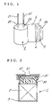
FIG. 2 is a sectional front view of a prior art solid electrolytic capacitor 1, and FIG. 1 is a perspective view of a capacitor element 2 (see Japanese Examined Patent Publication No. HEI4-19695 (1992)).
The solid electrolytic capacitor 1 includes an aluminum case 3 having a top opening, the capacitor element 2 contained in the case 3, and a rubber packing 30 which seals the top opening of the case 3. An upper edge portion of the case 3 is curved to fix the packing 30, and a plastic seat plate 31 is attached to the top of the case 3. Lead wires 21, 21 extend from the capacitor element 2 through the packing 30 and the seat plate 31, and then bent laterally.
As shown in FIG. 1, the capacitor element 2 includes an anode foil 4 of an aluminum foil coated with a dielectric oxide film and a cathode foil 5 of an aluminum foil, which are rolled together into a roll with a separator 6 of a dielectric material such as paper interposed therebetween and fixed by a tape 26. The capacitor element 2 further includes a solid electrolyte such as a TCNQ (7,7,8,8-tetracyanoquinodimethane) complex salt impregnated therein, or an electrically conductive polymer layer provided therein. Lead tabs 25, 25 respectively extend from the anode foil 4 and the cathode foil 5, and the lead wires 21, 21 respectively extend from the lead tabs 25, 25.
Where the electrically conductive polymer layer is formed between the foils 4 and 5, the capacitor element 2 is impregnated with a solution mixture containing n-butyl alcohol as a diluent, 3,4-ethylenedioxythiophene and iron p-toluenesulfonate, followed by thermal polymerization.
Although the solid electrolytic capacitor 1 having such a construction is widely used, there is a market demand for a capacitor having a smaller size and a greater capacitance. To this end, there has been proposed a capacitor which includes a cathode foil 5 coated with a metal nitride film as will be described below (see Japanese Unexamined Patent Publication No. 2000-114108).
An explanation will be given to the principle of the capacitance increase of the capacitor by coating the cathode foil 5 with the metal nitride film. In general, the dielectric oxide film is not intentionally formed on the cathode foil 5, but formed by natural oxidation. Therefore, the capacitance C of the capacitor is equivalent to a capacitance obtained by connecting the capacitance Ca of the anode foil 4 and the capacitance Cc of the cathode foil 5 in series, and represented by the following equation:
C=Ca×Cc/(Ca+Cc)=Ca×1/(Ca/Cc+1)
That is, if the cathode foil 5 has the capacitance Cc, the capacitance C of the capacitor is smaller than the capacitance Ca of the anode foil 4.
Where a film 52 of a metal nitride such as TiN is formed on the cathode foil 5 by sputtering or vapor deposition, however, molecules of the metal nitride supposedly intrude into the oxide film 51 to contact an aluminum base of the cathode foil 5. Therefore, the base and the metal nitride are electrically connected to each other, so that the cathode foil 5 has no capacitance. Thus, the capacitance of the capacitor can be increased without size increase of the capacitor.
However, this arrangement has the following drawbacks.
When the cathode foil 5 coated with the metal nitride film 52 is rolled for production of the capacitor element 2, the film 52 is liable to be exfoliated or cracked due to a tensile force or a twist force applied to the cathode foil 5. As a result, a leak current is increased. Further, where the electrically conductive polymer layer is formed between the foils 4 and 5 by impregnating the capacitor element 2 with the solution mixture containing 3,4-ethylenedioxythiophene and iron p-toluenesulfonate, the film 52 is liable to be eroded because the iron p-toluenesulfonate solution is highly acidic. This also results in the increase in the leak current.
The cathode foil 5 coated with the metal nitride film 52 are gradually oxidized over time. As a result, the cathode foil 5 has a capacitance, whereby the capacitance of the solid electrolytic capacitor 1 is liable to be reduced.
It is therefore an object of the present invention to provide a solid electrolytic capacitor substantially free from the increase in leak current and having a greater capacitance and a lower ESR (equivalent series resistance).
DISCLOSURE OF THE INVENTION
An inventive solid electrolytic capacitor 1 comprises a capacitor element 2 which includes an anode foil 4 and a cathode foil 5 rolled with a separator 6 interposed therebetween, and a solid electrolyte layer or an electrically conductive polymer layer provided therein. The cathode foil 5 is coated with a film of a titanium-containing compound metal nitride.
Alternatively, the cathode foil 5 is coated with a film comprising a titanium nitride layer. The film further comprises a titanium layer underlying the titanium nitride layer on the cathode foil 5.
BRIEF DESCRIPTION OF THE DRAWINGS
FIG. 1 is a perspective view of a prior art capacitor element;
FIG. 2 is a sectional front view of a prior art solid electrolytic capacitor;
FIG. 3 is a schematic sectional view illustrating a part of a capacitor element;
FIG. 4 is a sectional view for explaining how a metal nitride film intrudes into an oxide film to reach a base; and
FIG. 5 is a perspective view illustrating a scratch test.
BEST MODE FOR CARRYING OUT THE INVENTION
First Embodiment
One embodiment of the present invention will hereinafter be described in detail with reference to the attached drawings.
The solid electrolytic capacitor 1 has substantially the same overall construction as the prior art capacitor shown in FIG. 2. As shown in FIG. 1, a capacitor element 2 includes an anode foil 4 of an aluminum foil having an electrochemically formed film and a cathode foil 5 of an aluminum foil, which are rolled together into a roll with an insulative separator 6 interposed therebetween and fixed by a tape 26. The capacitor element 2 further includes a solid electrolyte such as a TCNQ complex salt impregnated therein, or an electrically conductive polymer layer provided therein. A pair of lead wires 21, 21 extend from the capacitor element 2.
A film including a titanium (Ti) thin layer and a titanium nitride thin layer is provided on the cathode foil 5 and, hence, has no capacitance as described above.
The capacitor element 2 is produced in the following manner. First, an aluminum foil strip cut out of an aluminum sheet is subjected to an etching process and an electrochemical process thereby to be formed with a dielectric oxide film 40 (see FIG. 3). Thus, the anode foil 4 is produced. The etching process roughens surfaces of the anode foil 4 to increase the surface area of the anode foil 4, thereby increasing the capacitance of the anode foil 4.
On the other hand, titanium layers are formed on surfaces of the cathode foil 5 by vapor deposition of titanium in vacuum, and titanium nitride layers are formed on the titanium layers by vapor deposition of titanium nitride in vacuum. The vapor deposition of titanium nitride is achieved by evaporating titanium in a nitrogen or ammonia atmosphere. After the formation of the titanium layers, nitrogen or the like is introduced into a vacuum chamber for prevention of formation of an oxide film while titanium is evaporated. Thus, the formation of the titanium nitride layers is achieved. Electron beam evaporation, arc plasma evaporation or the like may be employed for the formation of the titanium layers and the titanium nitride layers. Instead of the vapor deposition, sputtering or CVD may be employed for the film formation.
Then, the anode foil 4 and the cathode foil 5 are rolled together into a roll with an insulative separator 6 interposed therebetween, and fixed by a tape 26. Since the anode foil 4 is prepared by cutting the foil strip from the aluminum sheet as described above, end faces of the anode foil 4 are not formed with the dielectric oxide film. Therefore, the capacitor element 2 is subjected to an electrochemical process to form dielectric oxide films on the end faces of the anode foil 4. Thereafter, the capacitor element 2 is thermally treated at 280° C. for stabilization of the characteristics of the dielectric oxide films.
In turn, the capacitor element 2 is impregnated with a solution mixture containing n-butyl alcohol as a diluent, 3,4-ethylenedioxythiophene and iron p-toluenesulfonate, followed by thermal polymerization. Thus, an electrically conductive polymer layer 50 is formed between the foils 4 and 5, whereby the capacitor element 2 is completed. The capacitor element 2 is sealed in the case 3 in the same manner as in the prior art, whereby the solid electrolytic capacitor 1 is completed.
In this embodiment, the electrically conductive polymer layer 50 is formed of an electrically conductive polythiophene polymer, but may be formed of an electrically conductive polypyrrole or polyaniline polymer. Instead of the electrically conductive polymer layer, a solid electrolyte layer such as of a TCNQ complex salt may be formed.
FIG. 3 is a sectional view illustrating a part of the capacitor element 2 obtained after the impregnation process. The cathode foil 5 has the titanium layers formed by vapor deposition of titanium in vacuum, and the titanium nitride layers formed by vapor deposition of titanium nitride in vacuum. Analysis of a section of the cathode foil 5 reveals, as shown in FIG. 3, that the thin films formed on the cathode foil 5 each continuously vary from the titanium nitride layer 53 to the titanium layer 54 toward the cathode foil 5 and no definite interface is present between the titanium nitride layer 53 and the titanium layer 54. This is supposedly because nitrogen of titanium nitride deposited on the titanium layer is diffused into the titanium layer during the vapor deposition of titanium nitride or a subsequent step of the solid electrolytic capacitor production process.
Next, the results of tests performed on solid electrolytic capacitors actually produced according to the present invention and the prior art will be described below.
Table 1 shows electrical characteristics of the produced solid electrolytic capacitors in an initial state (immediately after the production). Prior Art Example 1 is a solid electrolytic capacitor employing an etched aluminum foil as a cathode foil thereof, and Prior Art Example 2 is a solid electrolytic capacitor employing an aluminum foil formed with a titanium thin film as a cathode foil thereof. Prior Art Example 3 is a solid electrolytic capacitor employing an aluminum foil formed with a titanium nitride thin film as a cathode foil thereof. Example is the inventive solid electrolytic capacitor previously described. The solid electrolytic capacitors 1 each have a diameter of 6.3 mm, a height of 6.0 mm, a rated voltage of 4V and a rated capacitance of 150 μF.
In Table 1,“Cap” indicates the capacitance of the capacitor (in units of μF), and “tan δ” indicates the dielectric loss of the capacitor (in units of %). “ESR” indicates the equivalent series resistance of the capacitor (in units of mΩ), and “LC” indicates the leak current of the capacitor (in units of μA). Values shown in Table 1 are each calculated as an average of measured values for 40 samples. The capacitance and the dielectric loss were measured at a frequency of 120 Hz. The equivalent series resistance was measured at a frequency of 100 kHz. The leak current was measured after a lapse of 2 minutes from application of a rated DC voltage to the solid electrolytic capacitor 1.
TABLE 1
Cathode Cap tanδ ESR LC ΔC/C
foil (μF) (%) (mΩ) (μA) (%)
Prior Art Al foil 151.4 2.8 33.7 25 −5.2
Example 1 treated by
etching
Prior Art Al foil 219.9 2.0 33.2 19 −4.2
Example 2 with Ti
deposited
Prior Art Al foil 227.3 1.9 34.0 30 −3.4
Example 3 with TiN
deposited
Example Al foil 253.7 1.7 34.2 20 −2.1
with Ti
and TiN
deposited
As can be understood from Table 1, the capacitance of Example is greater by about 10% than the capacitances of Prior Art Examples 2 and 3. The dielectric loss of Example is slightly smaller than the dielectric losses of Prior Art Examples. The equivalent series resistance of Example is greater than the equivalent series resistances of Prior Art Examples, but by a very small percentage. The leak current of Example is equivalent to the leak current of Prior Art Example 2 in which the aluminum foil formed with only the titanium thin film was employed, but is much smaller the leak currents of Prior Art Examples 1 and 3. According to the present invention, the initial capacitance of the solid electrolytic capacitor 1 can be thus increased without deterioration of the electrical characteristics including the dielectric loss.
After the measurement shown in Table 1, an endurance test was performed on the capacitors of Prior Art Examples and Example. In the endurance test, a rated voltage of 4V was applied to each of the capacitors at a temperature of 125° C. for 1000 hours. In Table 2, values of the capacitance and the equivalent series resistance measured before and after the test, and the change rate ΔC/C of the capacitance are shown. As in Table 1, the values are each calculated as an average of measured values for 40 samples. As can be understood from Table 2, the inventive solid electrolytic capacitor has a smaller capacitance change rate in absolute value than the prior art solid electrolytic capacitors and, even after the endurance test, had a great capacitance. After the endurance test, the capacitors of Prior Art Examples and Example have substantially the same equivalent series resistance. According to the present invention, the change in the capacitance of the solid electrolytic capacitor 1 over time can be reduced without deterioration of the equivalent series resistance as compared with the prior art.
TABLE 2
Initial After test
Cap (μF) ESR (mΩ) Cap (μF) ΔC/C (%) ESR (mΩ)
Prior Art 151.4 33.7 143.5 −5.2 35.6
Example 1
Prior Art 219.9 33.2 210.7 −4.2 35.2
Example 2
Prior Art 227.3 34.0 219.6 −3.4 35.9
Example 3
Example 253.7 34.2 248.4 −2.1 35.7
Second Embodiment
According to this embodiment, an aluminum foil having a film of a titanium-containing compound metal nitride such as aluminum titanium nitride (TiAlN) or chromium titanium nitride (TiCrN) formed on surfaces thereof by an ion plating method is used as a cathode foil 5. The aluminum foil may be preliminarily subjected or not subjected to an etching process. A capacitor element 2 produced by rolling an anode foil 4 and the cathode foil 5 is impregnated with an electrically conductive polymer and an oxidation agent in the same manner as in the first embodiment. An alcohol solution of 40 to 60 wt % iron p-toluenesulfonate is used as the oxidation agent.
The formation of the film is achieved through deposition by the ion plating method. The ion plating may be achieved by a direct current method, a high frequency method, a cluster ion beam deposition method or a hot cathode method. For the formation of the film, vacuum deposition, sputtering, thermal CVD, plasma CVD, photo CVD or laser CVD may be used instead of the ion plating method. The ion plating method supposedly ensures a higher adhesion strength of the film to the aluminum base than the sputtering method.
The applicant of the present invention produced a capacitor element 2 by using a cathode foil 5 formed with a film of aluminum titanium nitride (TiAlN), and then produced a solid electrolytic capacitor 1 of Example 1 by using this capacitor element 2.
Further, the applicant of the present invention produced a capacitor element 2 by using a cathode foil 5 formed with a film of chromium titanium nitride (TiCrN), and then produced a solid electrolytic capacitor 1 of Example 2 by using this capacitor element 2. A solid electrolytic capacitor 1 of Prior Art Example was produced in the same manner as in Prior Art Example 3 of the first embodiment by employing an aluminum foil formed with a titanium nitride thin film as a cathode foil 5.
These solid electrolytic capacitors 1 each have a rated voltage of 6.3V and a capacitance of 180 μF, and the cases thereof each have a diameter of 6.3 mm and a height of 6.0 mm.
The capacitances (“Cap” in units of μF) of the capacitors of Examples and Prior Art Example were measured at a frequency of 120 Hz, and the equivalent series resistances (“ESR” in units of mΩ) of the capacitors were measured at a frequency of 100 kHz. The leak currents (“LC” in units of μA) of the capacitors were measured after a rated direct current voltage was applied for two minutes. The results of the measurement are shown in Table 3, in which the values of the electrical characteristics are each calculated as an average of measured values for 20 samples.
TABLE 3
Cap ESR LC Scratch test
(μF) (mΩ) (μA) critical load (N)
Prior Art 185 11.8 27 60.3
Example
Example 1 220 10.7 0.7 80.3
Example 2 221 10.6 0.8 82.5
In the scratch test, as shown in FIG. 5, a wedge-like diamond blade 9 was dragged at a constant speed (about 2 mm/sec) while being pressed against the cathode foil 5 with loads applied to the diamond blade 9. A load applied when the film was exfoliated was determined.
As can be understood from a comparison between the results described above, the capacitance of the solid electrolytic capacitor 1 can be increased and the equivalent series resistance and the leak current can be correspondingly reduced by improving the adhesion strength of the film to the aluminum base. Although the capacitor elements 2 of the solid electrolytic capacitors 1 subjected to the measurement include the cathode foils 5 respectively formed with the aluminum titanium nitride film and the chromium titanium nitride film, a solid electrolytic capacitor having a cathode electrode 5 formed with a zirconium titanium nitride (TiZrN) film supposedly provides substantially the same results.
In the solid electrolytic capacitor 1 having the cathode foil 5 formed with the titanium-containing compound metal nitride film, the adhesion strength of the film to the aluminum base of the cathode foil 5 is improved by forming the film of the nonstoichiometric nitride compound (which cannot be represented by a simple chemical formula) on the cathode foil 5. A part of a metal in the compound metal nitride is oxidized in contact with air thereby to be passivated. Thus, a bonding force between metal molecules in the compound metal nitride is increased. As a result, the corrosion resistance of the film is improved.
Therefore, the film is less liable to be exfoliated and cracked when the cathode foil 5 is rolled. Further, the film is less liable to be eroded when the electrically conductive polymer layer is formed. Thus, a greater capacitance and a lower ESR can be achieved without increasing the leak current of the solid electrolytic capacitor 1.
It should be understood that the scope of the invention be not limited by the embodiments described above. For example, the top opening of the case 3 may be sealed with an epoxy resin. Further, the capacitor may have a construction of radial lead type.
INDUSTRIAL APPLICABILITY
  • 1. In the solid electrolytic capacitor 1 having the cathode foil 5 formed with the titanium-containing compound metal nitride film, the adhesion strength of the film to the aluminum base of the cathode foil 5 is improved by forming the film of the nonstoichiometric nitride compound (which cannot be represented by a simple chemical formula) on the cathode foil 5. A part of the metal in the compound metal nitride is oxidized in contact with air thereby to be passivated. Thus, a bonding force between metal molecules in the compound metal nitride is increased. As a result, the corrosion resistance of the film is improved.
Therefore, the film is less liable to be exfoliated and cracked when the cathode foil 5 is rolled. Further, the film is less liable to be eroded when the electrically conductive polymer layer is formed. Thus, a greater capacitance and a lower ESR can be achieved without increasing the leak current of the solid electrolytic capacitor 1.
  • 2. In the case of the solid electrolytic capacitor 1 having the cathode foil 5 formed with the titanium layer and the titanium nitride layer, the change in capacitance over time can be reduced as compared with the solid electrolytic capacitor 1 having the cathode foil 5 formed with only the titanium layer or the titanium nitride layer. The provision of the titanium layer and the titanium nitride layer on the cathode foil 5 increases the initial capacitance of the solid electrolytic capacitor 1 as compared with the prior art solid electrolytic capacitor 1.

Claims (4)

1. A solid electrolytic capacitor comprising a capacitor element which includes an anode foil and a cathode foil rolled with a separator interposed therebetween, and a layer of a solid electrolyte or an electrically conductive polymer provided therein, wherein the cathode foil is coated with a film of a titanium-containing compound metal nitride selected from the group consisting of aluminum titanium nitride, chromium titanium nitride, and zirconium titanium nitride.
2. A solid electrolytic capacitor as set forth in claim 1, wherein the electrolyte provided in the capacitor element is an electrically conductive polythiophene polymer.
3. A solid electrolytic capacitor comprising a capacitor element which includes an anode foil and a cathode foil rolled with a separator interposed therebetween, and a layer of a solid electrolyte or an electrically conductive polymer provided therein, the cathode foil being coated with a film comprising a titanium nitride layer, wherein the film further comprises a titanium layer underlying the titanium nitride layer on the cathode foil,
the film formed on the cathode foil continuously varying from the titanium nitride layer to the titanium layer toward the cathode foil.
4. A solid electrolytic capacitor as set forth in claim 3, wherein the electrolyte provided in the capacitor element is an electrically conductive polythiophene polymer.
US10/534,283 2002-11-19 2003-11-17 Solid electrolytic capacitor Expired - Lifetime US7158367B2 (en)

Priority Applications (1)

Application Number Priority Date Filing Date Title
US11/598,712 US7428139B2 (en) 2002-11-19 2006-11-14 Solid electrolytic capacitor

Applications Claiming Priority (5)

Application Number Priority Date Filing Date Title
JP2002334662 2002-11-19
JP2002-334662 2002-11-19
JP2003-67501 2003-03-13
JP2003067501A JP4201623B2 (en) 2002-11-19 2003-03-13 Solid electrolytic capacitor
PCT/JP2003/014603 WO2004047131A1 (en) 2002-11-19 2003-11-17 Solid electrolytic capacitor

Related Child Applications (1)

Application Number Title Priority Date Filing Date
US11/598,712 Continuation US7428139B2 (en) 2002-11-19 2006-11-14 Solid electrolytic capacitor

Publications (2)

Publication Number Publication Date
US20060018078A1 US20060018078A1 (en) 2006-01-26
US7158367B2 true US7158367B2 (en) 2007-01-02

Family

ID=32328318

Family Applications (2)

Application Number Title Priority Date Filing Date
US10/534,283 Expired - Lifetime US7158367B2 (en) 2002-11-19 2003-11-17 Solid electrolytic capacitor
US11/598,712 Expired - Lifetime US7428139B2 (en) 2002-11-19 2006-11-14 Solid electrolytic capacitor

Family Applications After (1)

Application Number Title Priority Date Filing Date
US11/598,712 Expired - Lifetime US7428139B2 (en) 2002-11-19 2006-11-14 Solid electrolytic capacitor

Country Status (7)

Country Link
US (2) US7158367B2 (en)
JP (1) JP4201623B2 (en)
KR (1) KR100987852B1 (en)
AU (1) AU2003280836A1 (en)
DE (1) DE10393733B4 (en)
TW (1) TWI230955B (en)
WO (1) WO2004047131A1 (en)

Cited By (4)

* Cited by examiner, † Cited by third party
Publication number Priority date Publication date Assignee Title
US20070115613A1 (en) * 2002-11-19 2007-05-24 Sanyo Electric Co., Ltd. Solid electrolytic capacitor
US8098479B1 (en) 2008-09-19 2012-01-17 Cornell Dubilier Marketing, Inc. Capacitor having zinc coated common edge with welded aluminum terminal
US9418796B2 (en) 2011-02-21 2016-08-16 Japan Capacitor Industrial Co., Ltd. Electrode foil, current collector, electrode, and electric energy storage element using same
US20160372273A1 (en) * 2014-03-28 2016-12-22 Panasonic Intellectual Property Management Co., Ltd. Power storage device and manufacturing method thereof

Families Citing this family (10)

* Cited by examiner, † Cited by third party
Publication number Priority date Publication date Assignee Title
JP2004265924A (en) * 2003-02-12 2004-09-24 Sanyo Electric Co Ltd Solid electrolytic capacitor
JP4716862B2 (en) 2005-12-09 2011-07-06 佐賀三洋工業株式会社 Solid electrolytic capacitor
CN100350070C (en) * 2005-12-15 2007-11-21 西安理工大学 Compound coating layer for improving micro drill service life and its preparation method
JP2010524200A (en) * 2007-04-12 2010-07-15 リンクロス株式会社 Bipolar supercapacitor and manufacturing method thereof
CN102483995A (en) * 2009-08-21 2012-05-30 日本贵弥功株式会社 Solid electrolytic capacitor
JP5995262B2 (en) * 2011-03-06 2016-09-21 ヘレウス ドイチェラント ゲーエムベーハー ウント カンパニー カーゲー Method for improving the electrical parameters in capacitors containing PEDOT / PSS as solid electrolyte by means of polyglycerol
JP6878896B2 (en) * 2016-03-31 2021-06-02 日本ケミコン株式会社 Electrolytic capacitors and their manufacturing methods
JP6996158B2 (en) * 2017-08-17 2022-01-17 日本ケミコン株式会社 Capacitors and their manufacturing methods
US11289487B2 (en) * 2018-02-23 2022-03-29 Micron Technology, Inc. Doped titanium nitride materials for DRAM capacitors, and related semiconductor devices, systems, and methods
DE102022103760A1 (en) 2022-02-17 2023-08-17 Tdk Electronics Ag Capacitor, method of manufacture and use

Citations (7)

* Cited by examiner, † Cited by third party
Publication number Priority date Publication date Assignee Title
JPH0471214A (en) 1990-07-12 1992-03-05 Nippon Chemicon Corp Aluminum electrode for electrolytic capacitor and manufacture thereof
JPH0574664A (en) 1991-09-13 1993-03-26 Elna Co Ltd Electrolytic capacitor and manufacture of electrode foil for the same capacitor
EP0905274A1 (en) 1996-04-03 1999-03-31 Zakrytoe Aktsionernoe Obschestvo "Ross Ltd" Method and device for applying porous coatings and cathode film of an electrolytic condenser
JP2000012400A (en) * 1998-06-19 2000-01-14 Nichicon Corp Electrode foil for aluminum electrolytic capacitor
WO2000019468A1 (en) * 1998-09-30 2000-04-06 Nippon Chemi-Con Corporation Solid electrolyte capacitor and its manufacturing method
US6052273A (en) * 1997-04-15 2000-04-18 Sanyo Electric Co., Ltd. Solid electrolyte capacitor
JP2000114108A (en) 1998-09-30 2000-04-21 Nippon Chemicon Corp Solid electrolytic capacitor and its manufacture

Family Cites Families (5)

* Cited by examiner, † Cited by third party
Publication number Priority date Publication date Assignee Title
JP2968800B2 (en) 1989-04-21 1999-11-02 株式会社神戸製鋼所 Method for producing electrode material for electrolytic capacitor
JPH065476A (en) 1992-06-19 1994-01-14 Toyo Metaraijingu Kk Large capacitance electrolytic capacitor
JP4560940B2 (en) * 1999-11-04 2010-10-13 パナソニック株式会社 Solid electrolytic capacitor and manufacturing method thereof
JP2002299181A (en) * 2001-03-29 2002-10-11 Nippon Chemicon Corp Solid electrolyte capacitor
JP4201623B2 (en) * 2002-11-19 2008-12-24 三洋電機株式会社 Solid electrolytic capacitor

Patent Citations (9)

* Cited by examiner, † Cited by third party
Publication number Priority date Publication date Assignee Title
JPH0471214A (en) 1990-07-12 1992-03-05 Nippon Chemicon Corp Aluminum electrode for electrolytic capacitor and manufacture thereof
JPH0574664A (en) 1991-09-13 1993-03-26 Elna Co Ltd Electrolytic capacitor and manufacture of electrode foil for the same capacitor
EP0905274A1 (en) 1996-04-03 1999-03-31 Zakrytoe Aktsionernoe Obschestvo "Ross Ltd" Method and device for applying porous coatings and cathode film of an electrolytic condenser
JP2000509101A (en) 1996-04-03 2000-07-18 ザクトリー アクティオネルノエ オブシェストボ “ロス リミテッド” Method and apparatus for forming a porous coating of an electrolytic capacitor and a cathode film
US6052273A (en) * 1997-04-15 2000-04-18 Sanyo Electric Co., Ltd. Solid electrolyte capacitor
JP2000012400A (en) * 1998-06-19 2000-01-14 Nichicon Corp Electrode foil for aluminum electrolytic capacitor
WO2000019468A1 (en) * 1998-09-30 2000-04-06 Nippon Chemi-Con Corporation Solid electrolyte capacitor and its manufacturing method
JP2000114108A (en) 1998-09-30 2000-04-21 Nippon Chemicon Corp Solid electrolytic capacitor and its manufacture
US6515847B1 (en) * 1998-09-30 2003-02-04 Nippon Chemi-Con Corporation Solid electrolyte capacitor and its manufacturing method

Cited By (7)

* Cited by examiner, † Cited by third party
Publication number Priority date Publication date Assignee Title
US20070115613A1 (en) * 2002-11-19 2007-05-24 Sanyo Electric Co., Ltd. Solid electrolytic capacitor
US7428139B2 (en) * 2002-11-19 2008-09-23 Sanyo Electric Co., Ltd. Solid electrolytic capacitor
US8098479B1 (en) 2008-09-19 2012-01-17 Cornell Dubilier Marketing, Inc. Capacitor having zinc coated common edge with welded aluminum terminal
US9418796B2 (en) 2011-02-21 2016-08-16 Japan Capacitor Industrial Co., Ltd. Electrode foil, current collector, electrode, and electric energy storage element using same
US20160372273A1 (en) * 2014-03-28 2016-12-22 Panasonic Intellectual Property Management Co., Ltd. Power storage device and manufacturing method thereof
US9887045B2 (en) * 2014-03-28 2018-02-06 Panasonic Intellectual Property Management Co., Ltd. Power storage device and manufacturing method thereof
US10522297B2 (en) 2014-03-28 2019-12-31 Panasonic Intellectual Property Management Co., Ltd. Power storage device and manufacturing method thereof

Also Published As

Publication number Publication date
KR100987852B1 (en) 2010-10-13
JP2004221512A (en) 2004-08-05
US20060018078A1 (en) 2006-01-26
DE10393733B4 (en) 2014-08-21
AU2003280836A1 (en) 2004-06-15
TW200416760A (en) 2004-09-01
DE10393733T5 (en) 2005-11-10
AU2003280836A8 (en) 2004-06-15
US20070115613A1 (en) 2007-05-24
KR20050085034A (en) 2005-08-29
TWI230955B (en) 2005-04-11
WO2004047131A1 (en) 2004-06-03
US7428139B2 (en) 2008-09-23
JP4201623B2 (en) 2008-12-24

Similar Documents

Publication Publication Date Title
US7428139B2 (en) Solid electrolytic capacitor
US6515847B1 (en) Solid electrolyte capacitor and its manufacturing method
US20140036416A1 (en) Electrode foil and method for manufacturing same, and capacitor
US7846218B2 (en) Method of manufacturing electrolytic capacitor
US20100020472A1 (en) Electrolytic capacitor and method of making the same
US7391604B2 (en) Solid electrolytic capacitor
US8358497B2 (en) Electrode foil for capacitor, electrolytic capacitor using the same, and method for manufacturing electrode foil for capacitor
JP4285523B2 (en) Electrode foil for solid electrolytic capacitor and manufacturing method thereof
CN102082027A (en) Electrolytic capacitor and manufacturing method thereof
JP2012044212A (en) Electrolytic capacitor
US7167356B2 (en) Solid electrolytic capacitor
US20100053848A1 (en) Niobium solid electrolytic capacitor
US7885054B2 (en) Solid electrolytic capacitor
JP2000114109A (en) Solid electrolytic capacitor and its manufacture
CN100521012C (en) Solid electrolytic capacitor
JP4114700B2 (en) Solid electrolytic capacitor and manufacturing method thereof
JPH03150823A (en) Aluminum electrode for electrolytic capacitor
JP2001358040A (en) Solid electrolytic capacitor
JP2001307962A (en) Solid electrolytic capacitor and the manufacturing method

Legal Events

Date Code Title Description
AS Assignment

Owner name: SANYO ELECTRIC CO., LTD., JAPAN

Free format text: ASSIGNMENT OF ASSIGNORS INTEREST;ASSIGNORS:FUJIMOTO, KAZUMASA;YOSHIMITSU, SATORU;YOSHIDA, YASUSHI;AND OTHERS;REEL/FRAME:017080/0429

Effective date: 20050425

Owner name: SAGA SANYO INDUSTRIES CO., LTD., JAPAN

Free format text: ASSIGNMENT OF ASSIGNORS INTEREST;ASSIGNORS:FUJIMOTO, KAZUMASA;YOSHIMITSU, SATORU;YOSHIDA, YASUSHI;AND OTHERS;REEL/FRAME:017080/0429

Effective date: 20050425

Owner name: JAPAN CAPACITOR INDUSTRIAL CO., LTD., JAPAN

Free format text: ASSIGNMENT OF ASSIGNORS INTEREST;ASSIGNORS:FUJIMOTO, KAZUMASA;YOSHIMITSU, SATORU;YOSHIDA, YASUSHI;AND OTHERS;REEL/FRAME:017080/0429

Effective date: 20050425

STCF Information on status: patent grant

Free format text: PATENTED CASE

FPAY Fee payment

Year of fee payment: 4

FPAY Fee payment

Year of fee payment: 8

MAFP Maintenance fee payment

Free format text: PAYMENT OF MAINTENANCE FEE, 12TH YEAR, LARGE ENTITY (ORIGINAL EVENT CODE: M1553)

Year of fee payment: 12