US7137635B2 - Expandable in-line skate - Google Patents
Expandable in-line skate Download PDFInfo
- Publication number
- US7137635B2 US7137635B2 US10/768,983 US76898304A US7137635B2 US 7137635 B2 US7137635 B2 US 7137635B2 US 76898304 A US76898304 A US 76898304A US 7137635 B2 US7137635 B2 US 7137635B2
- Authority
- US
- United States
- Prior art keywords
- cup
- toe cup
- skate
- toe
- base
- Prior art date
- Legal status (The legal status is an assumption and is not a legal conclusion. Google has not performed a legal analysis and makes no representation as to the accuracy of the status listed.)
- Expired - Lifetime, expires
Links
- 210000003423 ankle Anatomy 0.000 claims description 22
- 210000002683 foot Anatomy 0.000 claims description 13
- 230000013011 mating Effects 0.000 claims description 2
- 239000000463 material Substances 0.000 description 6
- 238000010276 construction Methods 0.000 description 4
- 230000007423 decrease Effects 0.000 description 2
- 230000003247 decreasing effect Effects 0.000 description 2
- 230000000881 depressing effect Effects 0.000 description 2
- 230000000994 depressogenic effect Effects 0.000 description 2
- 210000004744 fore-foot Anatomy 0.000 description 2
- 230000002045 lasting effect Effects 0.000 description 2
- 230000000717 retained effect Effects 0.000 description 2
- 210000003813 thumb Anatomy 0.000 description 2
- RTAQQCXQSZGOHL-UHFFFAOYSA-N Titanium Chemical compound [Ti] RTAQQCXQSZGOHL-UHFFFAOYSA-N 0.000 description 1
- 229910045601 alloy Inorganic materials 0.000 description 1
- 239000000956 alloy Substances 0.000 description 1
- 229910052782 aluminium Inorganic materials 0.000 description 1
- XAGFODPZIPBFFR-UHFFFAOYSA-N aluminium Chemical compound [Al] XAGFODPZIPBFFR-UHFFFAOYSA-N 0.000 description 1
- 238000011161 development Methods 0.000 description 1
- 230000018109 developmental process Effects 0.000 description 1
- 239000013013 elastic material Substances 0.000 description 1
- 239000006263 elastomeric foam Substances 0.000 description 1
- 229920003247 engineering thermoplastic Polymers 0.000 description 1
- 239000004744 fabric Substances 0.000 description 1
- 239000000835 fiber Substances 0.000 description 1
- 210000003811 finger Anatomy 0.000 description 1
- 229920002457 flexible plastic Polymers 0.000 description 1
- 210000005224 forefinger Anatomy 0.000 description 1
- 239000010985 leather Substances 0.000 description 1
- 229910052751 metal Inorganic materials 0.000 description 1
- 239000002184 metal Substances 0.000 description 1
- 150000002739 metals Chemical class 0.000 description 1
- 238000000034 method Methods 0.000 description 1
- 230000002093 peripheral effect Effects 0.000 description 1
- 229920001169 thermoplastic Polymers 0.000 description 1
- 229920001187 thermosetting polymer Polymers 0.000 description 1
- 239000004634 thermosetting polymer Substances 0.000 description 1
- 239000004416 thermosoftening plastic Substances 0.000 description 1
- 239000010936 titanium Substances 0.000 description 1
- 229910052719 titanium Inorganic materials 0.000 description 1
- ATCJTYORYKLVIA-SRXJVYAUSA-N vamp regimen Chemical compound O=C1C=C[C@]2(C)[C@H]3[C@@H](O)C[C@](C)([C@@](CC4)(O)C(=O)CO)[C@@H]4[C@@H]3CCC2=C1.C=1N=C2N=C(N)N=C(N)C2=NC=1CN(C)C1=CC=C(C(=O)N[C@@H](CCC(O)=O)C(O)=O)C=C1.O([C@H]1C[C@@](O)(CC=2C(O)=C3C(=O)C=4C=CC=C(C=4C(=O)C3=C(O)C=21)OC)C(=O)CO)[C@H]1C[C@H](N)[C@H](O)[C@H](C)O1.C([C@H](C[C@]1(C(=O)OC)C=2C(=CC3=C(C45[C@H]([C@@]([C@H](OC(C)=O)[C@]6(CC)C=CCN([C@H]56)CC4)(O)C(=O)OC)N3C=O)C=2)OC)C[C@@](C2)(O)CC)N2CCC2=C1NC1=CC=CC=C21 ATCJTYORYKLVIA-SRXJVYAUSA-N 0.000 description 1
Images


Classifications
-
- A—HUMAN NECESSITIES
- A63—SPORTS; GAMES; AMUSEMENTS
- A63C—SKATES; SKIS; ROLLER SKATES; DESIGN OR LAYOUT OF COURTS, RINKS OR THE LIKE
- A63C17/00—Roller skates; Skate-boards
- A63C17/04—Roller skates; Skate-boards with wheels arranged otherwise than in two pairs
- A63C17/06—Roller skates; Skate-boards with wheels arranged otherwise than in two pairs single-track type
-
- A—HUMAN NECESSITIES
- A43—FOOTWEAR
- A43B—CHARACTERISTIC FEATURES OF FOOTWEAR; PARTS OF FOOTWEAR
- A43B3/00—Footwear characterised by the shape or the use
- A43B3/26—Footwear characterised by the shape or the use adjustable as to length or size
-
- A—HUMAN NECESSITIES
- A43—FOOTWEAR
- A43B—CHARACTERISTIC FEATURES OF FOOTWEAR; PARTS OF FOOTWEAR
- A43B5/00—Footwear for sporting purposes
- A43B5/16—Skating boots
- A43B5/1608—Skating boots size adjustable
-
- A—HUMAN NECESSITIES
- A63—SPORTS; GAMES; AMUSEMENTS
- A63C—SKATES; SKIS; ROLLER SKATES; DESIGN OR LAYOUT OF COURTS, RINKS OR THE LIKE
- A63C17/00—Roller skates; Skate-boards
-
- A—HUMAN NECESSITIES
- A63—SPORTS; GAMES; AMUSEMENTS
- A63C—SKATES; SKIS; ROLLER SKATES; DESIGN OR LAYOUT OF COURTS, RINKS OR THE LIKE
- A63C17/00—Roller skates; Skate-boards
- A63C17/0086—Roller skates adjustable in length to fit the size of the foot
-
- A—HUMAN NECESSITIES
- A63—SPORTS; GAMES; AMUSEMENTS
- A63C—SKATES; SKIS; ROLLER SKATES; DESIGN OR LAYOUT OF COURTS, RINKS OR THE LIKE
- A63C2203/00—Special features of skates, skis, roller-skates, snowboards and courts
- A63C2203/48—Roller or ice skates adjustable in width
Definitions
- the present invention relates to skates such as in-line skates and, in particular, to an in-line skate having a toolless size adjustment mechanism for adjusting the shoe size of the skate.
- conventional in-line roller skates include an upper boot secured to or integrally formed with a rigid or semirigid base.
- the base is secured along its length, including at heel and toe ends, to a rigid frame.
- a plurality of wheels is journaled transversely along a longitudinal axis between the sidewalls of the frame.
- the in-line skate includes a skate boot secured to a frame and contains a liner.
- the frame carries a plurality of wheels.
- the skate boot includes a heel portion, a cuff, a tongue, and a toe portion.
- the toe portion is selectively connected to the frame via a bolt, which is received by a nut.
- the bottom wall of the toe portion includes an elongate slot extending in the longitudinal dimension of the skate through which the bolt passes.
- the toe portion When assembled with the heel portion, the toe portion may move along a line of travel that is generally parallel to the longitudinal dimension of the skate, by loosening the nut.
- This configuration requires a tool, inserted upwardly between the wheels, to adjust the size of the skate, which is inconvenient. Repeated adjustment may lead to stripping of the nut, thus limiting the skate's ability to adjust.
- the bolt and/or nut may be lost.
- the present invention is directed to an adjustable in-line skate wherein the width of the skate may be selectively modified by the user to achieve a comfortable fit.
- a size-adjustable in-line skate in an embodiment of the invention, includes a frame that rotatably supports the wheels of the skate and a base, attached to the frame, which defines a platform and a heel cup.
- a semirigid toe cup is attachable to the base, the toe cup being adapted to receive the forefoot portion of the skate upper.
- the toe cup includes a floor portion that is adjacent to the base platform when the toe cup is attached to the base.
- a slit extends generally longitudinally along most of the length of the floor portion of the toe cup, such that the width of the toe cup may be adjusted by elastically deforming the toe cup.
- the toe cup slidably engages the floor of the base such that the length of the skate is also adjustable.
- the width of the toe cup is determined by the adjustable length of the skate.
- the floor of the base further comprises an upwardly extending tab member and the toe cup further comprises an angled slot that is adapted to slidably receive the tab member, such that slidably adjusting the toe cup relative to the floor of the base will cause the transverse dimension of the slit in the toe cup to change.
- the base of the skate includes an upwardly extending longitudinal rail having a T-shaped cross section, the rail having a plurality of indents along at least one side, and further, wherein the toe cup includes a T-shaped slot that slidably engages the rail, and the toe cup further comprising a transverse engagement member that selectively engages at least one of the plurality of indents along the rail to lock the toe cup longitudinally with respect to the base.
- the skate further comprises an ankle cuff that is pivotally attached to the heel cup.
- the a pair of locking hooks on the toe cup engages a corresponding pair of locking hooks on the base, to preclude the toe cup from inadvertently disengaging from the frame.
- FIG. 1 illustrates an isometric view of a toolless, size-adjustable in-line skate constructed in accordance with aspects of the present invention
- FIG. 2 illustrates a side assembly view of the skate shown in FIG. 1 ;
- FIG. 3 illustrates an isometric view of the actuator shown in FIG. 2 ;
- FIG. 4 illustrates a top view of the toe end of the base shown in FIG. 2 ;
- FIG. 5 illustrates a top view of the toe cup shown in FIG. 2 ;
- FIG. 6 illustrates a bottom view of the toe cup shown in FIG. 2 ;
- FIG. 7 illustrates a top cut-away view of the toe cup slideably mounted to the base in a fixed position
- FIG. 8 illustrates a top cut-away view of the actuator being depressed and disengaged with the detents, and the toe cup translated in the longitudinal dimension to a second position
- FIG. 9 illustrates an isometric view of another embodiment of a toolless, size-adjustable in-line skate constructed in accordance with aspects of the present invention.
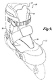
- FIG. 10 is a side view of an in-line skate according to another embodiment of the present invention, wherein both the length and the width of the in-line skate are adjustable;
- FIG. 11 is an isometric, exploded view of the base and toe cup of the in-line skate shown in FIG. 10 ;
- FIG. 12 is another isometric, exploded view of the base and toe cup of the in-line skate shown in FIG. 10 , showing the bottom of the toe cup;
- FIG. 13 is a partially exploded side view of the in-line skate shown in FIG. 10 ;
- FIGS. 14A , 14 B, and 14 C are partially cut-away plan views of the base and toe cup of the in-line skate shown in FIG. 10 , showing the steps to adjust the size of the in-line skate;
- FIGS. 15A and 15B illustrate a base and toe cup for another embodiment of the present invention, wherein the width of the toe cup is adjustable independently of the length of the skate.
- FIG. 1 A suitable embodiment of a toolless, size-adjustable in-line skate 10 constructed in accordance with the present invention is illustrated in FIG. 1 .
- the skate 10 includes a substantially nonrigid upper 12 that receives and surrounds a skater's foot and ankle.
- the upper 12 is mounted on and secured to the upper surface of a base 14 .
- the upper 12 is supported by a substantially rigid external support, including a slidably adjustable toe cup 16 extending upwardly from the toe end 18 of the base 14 , a heel cup 20 extending upwardly from the heel end 22 of the base 14 , and an ankle cuff 24 pivotally secured to the base 14 .
- the base 14 is mounted to or integrally formed with a frame 26 , which extends longitudinally beneath the base 14 .
- a plurality of ground engaging members, such as wheels 28 A, 28 B, 28 C, and 28 D, is journaled between first and second opposing longitudinal sidewalls 32 A and 32 B of the frame 26 .
- the toe cup 16 includes an actuator 34 , such as a push-button, which can be depressed or translated so that the slideably adjustable toe cup 16 may slide along the longitudinal axis of the skate to adjust the shoe size of the skate 10 .
- nonrigid upper 12 and substantially rigid outer support are disclosed in U.S. Pat. No. 5,437,466, hereby expressly incorporated by reference.
- an internal support structure can be used with the nonrigid upper, as described in U.S. Pat. No. 6,168,172, hereby expressly incorporated by reference.
- various components of the nonrigid portions of the support can be modified for a higher degree of rigidity.
- the upper 12 includes a toe end 36 , a heel end 38 , and diametrically opposed sides 40 A and 40 B that define a vamp opening 42 .
- the toe end 36 is separate from the rest of the upper 12 and, when assembled, overlaps with the sides 40 A and 40 B.
- a tongue 44 is fastened to the upper 12 , extending upwardly beneath the vamp opening 42 .
- the vamp opening 42 is drawn closed and the soft upper is fitted and drawn about the skater's foot by a lacing system 46 . Alternate constructions that do not use a lacing system are within the scope of the invention and will be described below.
- An ankle cuff strap 48 connected to the ankle cuff 24 may be selectively secured to fasten the cuff 24 about the skater's lower leg, above the ankle cuff 24 .
- the upper 12 may include other components, such as a sole or the like.
- the upper 12 may be drawn closed by an alternative closure system to securely couple the upper to a user's foot.
- an alternative closure system is shown wherein the vamp opening 42 of the upper 12 of skate 10 is drawn closed by an elastic web 54 that extends across a lower portion of the vamp opening 42 , overlying the tongue 44 .
- the alternative closure system may further includes an instep strap 56 secured across the upper 12 , extending from a lateral side of the heel cup to a medial side of the heel cup, below the ankle.
- the upper 12 of the skate 10 is constructed of a majority of substantially nonrigid materials, and is supported by a rigid, or at least semirigid, external support.
- the substantially nonrigid upper 12 is suitably constructed from flexible materials such as fabric, leather, flexible plastics, and cushioning materials such as fiber, fleece, batting or elastomeric foams.
- the toe end 36 of the upper 12 is securely fastened to the toe cup 16 , such as by riveting, stitching, bonding, using bolts or the like.
- the toe cup 16 includes a bottom wall 60 and medial and lateral sidewalls 62 A and 62 B that extend upwardly around the toe end 36 of the upper 12 .
- the toe cup 16 is slideably coupled to the toe end 18 of the base 14 with a fastener 52 , such as a rivet, bolt, screw or the like, that will be described in more detail below.
- the toe cup 16 includes an actuator 34 operatively connected within the medial sidewall 62 A and is a part of a size adjustment mechanism 64 for adjusting the shoe size of the skate.
- the actuator 34 and the size adjustment mechanism 64 will be described in more detail below.
- the heel end 38 of upper 12 is securely fastened to the base 14 , such as by riveting, bonding, stitching, using bolts or the like, and is supported by a rigid heel cup 20 .
- the rigid heel cup 20 may be integrally formed with the base 14 or secured to the base 14 , and extends upwardly therefrom on the lateral and medial sides of the heel end 38 of the upper 12 .
- the ankle cuff 24 is pivotally secured to the upper lateral and medial sides of the heel cup 20 , to pivot forwardly and rearwardly at about the natural pivot axis of the ankle.
- the ankle cuff 24 wraps the rear, lateral, and medial sides of the leg, above the ankle.
- the ankle cuff strap 48 includes a quick release ratcheting buckle assembly to selectively secure and tighten the cuff about the leg.
- the upper 12 of the skate 10 extends continuously upward from the base to above the upper edge of the ankle cuff 24 .
- the present invention is also suitably used with skates having an upper that is discontinuous, having a separate cuff pad, or that terminates below the ankle.
- the frame 26 is mounted below or integrally formed with the base 14 , and extends downwardly from the base 14 .
- the frame 26 includes first and second opposing longitudinal sidewalls 32 A and 32 B.
- the frame 26 carries four wheels, 28 A, 28 B, 28 C, and 28 D, journaled between the opposing sidewalls 32 A and 32 B.
- Each wheel includes a center hub 70 and bearing assembly (not shown) that are mounted rotatably on an axle 74 that is inserted through aligned apertures 76 of the sidewalls 32 A and 32 B, and that are retained by cap screws 78 .
- the frame 26 can be formed from any suitable rigid material, such as aluminum, titanium, other metals and alloys, engineering thermoplastics, and fiber-reinforced thermoplastics or thermosetting polymers.
- An optional brake member may be fastened to the frame, rearward of the wheel 28 D, which is well known in the art.
- the skate 10 includes a size adjustment mechanism 64 having an actuator 34 for adjusting the shoe size of the skate 10 , which was briefly discussed above and will now be described in greater detail with reference to FIGS. 4–9 .
- the toe end 18 of the base 14 extends as a generally oval-shaped member having a substantially flat top surface 80 suitably sized for supporting the slideably adjustable toe cup.
- the toe end 18 includes an elongate, generally rectangular recess or slot 82 open to the top surface thereof, and extending in the longitudinal dimension of the skate for receiving a boss of corresponding shape located at the bottom surface of the toe cup.
- the slot 82 includes an aperture 84 on the bottom surface of the slot 82 , and is positioned at the forward portion of the slot 82 and extends through the base 14 .
- the aperture 84 is of a suitable shape and size to receive a fastener 52 , such as a rivet ( FIG. 2 ), to securely couple the toe cup to the base 14 .
- detent notches 88 A, 88 B, 88 C, 88 D, and 88 E Positioned at the rear portion of the slot 82 and formed into the medial side thereof is a series of detent notches 88 A, 88 B, 88 C, 88 D, and 88 E.
- the detent notches form teeth that are tapered in shape and protrude horizontally inward toward the centerline of the slot 82 . While shown in FIG. 4 as tapered in shape, the detent notches can be of any suitable size or geometry without departing from the scope of the present invention.
- the detent notches 88 A, 88 B, 88 C, 88 D, and 88 E are operable to engage or mesh with correspondingly shaped teeth on the actuator to form the indexing size adjustment mechanism, the operation of which will be described in more detail below.
- the top surface 80 of the toe end 18 further includes an elongate rib member 90 that extends substantially parallel with the slot 82 .
- the elongate rib member 90 mates with and slides within a slot of corresponding shape within the bottom wall of the toe cup to provide a guide mechanism that prevents rotation of the toe cup as it slideably translates on the toe end 18 .
- the toe cup 16 includes a bottom wall 92 having a substantially flat bottom surface 94 for slideably engaging with the top surface 80 of the base 14 .
- the toe cup 16 also includes medial and lateral sidewalls 96 A and 96 B that extend upwardly from the bottom wall 92 to form a cavity 98 .
- the cavity 98 is of a suitable dimension to receive the forefoot of a skater. While shown as a toe cup, it will be appreciated that the slideable support member can be a toe member such as a substantially flat plate or bottom wall 92 .
- the bottom wall 92 of the toe cup 16 includes a longitudinally disposed slot 108 open to the bottom surface 94 for mating with the elongate rib member 90 of the base 14 described above.
- Extending downwardly from the bottom surface 94 of the toe cup 16 is a generally rectangular shaped boss 102 with rounded edges.
- the boss 102 extends lengthwise in the longitudinal dimension of the skate and is suitably shaped and positioned at the forward end of the bottom surface 94 to be slideably received within the slot 82 of the base 14 ( FIG. 4 ).
- the boss 102 and corresponding slot 82 of the base form a guide mechanism which, along with the guide mechanism described above, comprised of the slot 108 and the elongate rib member 90 , prevents rotation of the toe cup 16 as it slideably translates on the toe end of the base 14 .
- the boss 102 is provided with an elongated slot 104 open to the bottom surface and also extending in the longitudinal dimension of the skate for passing a fastener 52 , such as a rivet, when the toe cup 16 is slideably translated with respect to the base 14 .
- the top surface of the bottom wall 92 includes an elongate slot 106 formed by downwardly descending sidewalls of the boss that is concentric with slot 104 .
- the slot 106 is similar in shape, but larger in size, than slot 104 to form a shoulder 109 for supporting the head of the fastener 52 as the slots 104 and 106 pass the fastener when the toe cup 16 is slidably translated with respect to the base.
- the fastener 52 can be removable such as a bolt or screw, or can be nonremovable or permanent, such as a rivet. In either case, the fastener 52 securely retains the toe cup on the base during adjustment.
- the bottom wall 92 includes a horizontally disposed slot 110 , which is transverse to the longitudinally dimension of the skate.
- the slot 110 is suitably dimensioned to receive the actuator 34 of the size adjustment mechanism in a slideable fashion.
- the slot 110 also includes a tab portion 112 integrally formed at its innermost surface for receiving a biasing member 118 , such as a spring.
- Integrally formed in the bottom wall 92 are two diametrically opposed tabs 114 A and 114 B for supporting the actuator as it slides horizontally within the slot 110 .
- the rear portion of the medial sidewall 96 A includes an aperture 116 for allowing a portion of the actuator to protrude through the medial sidewall 96 A.
- the actuator 34 is constructed as a unitary body having a generally T-shaped cross section.
- the actuator includes an upper member 120 and a lower member 122 extending transversely from the upper member 120 to form the T-shaped actuator.
- the actuator 34 includes a face 124 , preferably grooved and suitably sized for engagement with the thumb or forefinger of a skater.
- the actuator 34 includes substantially and parallel upper and lower surfaces, spaced to slidably seat within the slot 110 , flush with the top surface of the toe cup 16 .
- the lower member 122 extends from the upper member 120 in a downward direction between the opposed tabs 114 A, 114 B that support the actuator 34 and guide the horizontal translation of the actuator 34 .
- Two engagement members or teeth 126 A and 126 B are disposed on the opposite end of the actuator 34 .
- the teeth are preferably tapered in geometry and oriented toward the face 124 of the actuator 34 . It will be appreciated that the size and geometry of the teeth 126 A, 126 B correspond to the size and geometry of the detent notches 88 A– 88 E, so that the teeth may properly mesh with the detent notches.
- the actuator 34 also includes a tab 130 connected to the rearward surface of the actuator 34 that engages one end of the biasing member 118 ( FIGS. 5 and 6 ). The biasing member 118 biases the actuator 34 outwardly toward the medial sidewall of the toe cup so that the teeth 126 A and 126 B selectively mesh with the detent notches 88 A– 88 E of the base 14 .
- FIG. 7 depicts the toe cup 16 fixed at a desired longitudinal position relative to the heel end of the base (not shown).
- the toe cup 16 is supported by the top surface of the base 14 , whereby the boss 102 is nested within the elongate slot 82 of the base 14 .
- the toe cup 16 is securely fastened to the base 14 via the fastener 52 , which is slideably received within the slot 104 with the head portion of the fastener 52 supported by the shoulder 108 .
- the actuator 34 is biased by the biasing member 18 outward such that the teeth 126 A, 126 B located on the bottom of the actuator 34 mesh with two of the detent notches 88 A– 88 E formed within the slot 82 ( FIG. 7 shows teeth 126 A, 126 B meshing with detent notches 88 A, 88 B). In this position, a skater may skate without the toe cup 16 sliding relative to the base 14 .
- the skater may translate the actuator 34 by depressing the actuator inward with her finger, which is depicted in FIG. 8 .
- the actuator 34 is linearly translated in the horizontal plane against the force of the biasing member 118 to disengage the teeth 126 A and 126 B of the actuator 34 from the detent notches 88 A– 88 E of the slot 82 .
- the toe cup 16 may slide or translate in the longitudinal dimension relative to the heel end of the base (note shown) to increase the size of the cavity formed by the upper so that the upper 12 may receive a larger foot of a skater.
- the toe cup 16 and actuator 34 travel together during adjustment. In the embodiment shown, this can be easily done by grasping the toe cup 16 with one hand and, in one movement, depress the actuator 34 with the thumb and translate the toe cup 16 .
- the boss 102 and elongate rib member 90 slide relative to the slots 82 and 108 , respectively, preventing the toe cup 16 from rotating.
- the actuator 34 may be released.
- the biasing force of the biasing member 118 linearly translates the actuator 34 outwardly, and the skater may adjust the toe cup 16 until the teeth 126 A, 126 B mesh with the desired detent notches 88 A– 88 E, as discussed above.
- the tapered shape of the teeth on the actuator 34 guide the actuator into locking engagement when the actuator 34 is released.
- FIG. 10 another embodiment of an adjustable in-line skate 200 is shown, wherein both the width and the length of the skate 200 are adjustable, as discussed in detail below.
- This skate 200 includes a frame 226 having parallel sidewalls 232 (one visible in FIG. 10 ) that rotatably supports a plurality of wheels 228 .
- a base 214 is fixedly attached to the frame 226 .
- a heel cup 220 is disposed at the rearward end of the base 214 , and a toe cup 216 is disposed at the forward end of the base 214 .
- An ankle cuff 224 is pivotally attached to the heel cup 220 .
- the ankle cuff 224 includes a strap 223 and/or other attachment mechanism for securing the skate 200 about the user's ankle.
- An upper 212 for receiving a user's foot (not shown), is attached to the base 214 .
- the upper 212 includes a toe portion 236 and a separable heel portion 238 that slidably engage the toe portion 236 .
- the base 214 includes the heel cup 220 , which may be formed integrally with the base 214 , and a platform portion 280 .
- a T-shaped rail 282 extends upwardly from the platform portion 280 .
- the rail 282 includes a number of locking detents 288 along one side.
- a T-shaped guide tab 284 extends upwardly from a rearward end of the platform 280 , and a pair of first hook members 286 (one visible in FIG. 11 ) also extends upwardly from the rearward end of the platform 280 .
- the function of the rail 282 , guide tab 284 , and first hook members 286 is explained below.
- the toe cup 216 is separable from the base 214 and slidably engages the base 214 such that the length of the skate 200 may be selectively adjusted.
- the toe cup 216 includes a floor portion 250 having a peripheral wall 252 extending upwardly about a portion of the periphery of the floor portion 250 .
- An elongate slit 254 extends from a back end of the toe cup 216 , forwardly for most of the length of the toe cup 216 .
- the toe cup 216 is made from a sufficiently elastic material that the width of the toe cup 216 may be elastically adjusted by increasing or decreasing the transverse dimension (i.e., the variable width) of the elongate slit 254 , as discussed below.
- the rearward end of the toe cup 216 includes a pair of second hook members 256 , that is adapted to engage the first hook members 286 on the base 214 .
- the second hook members 256 extend on narrow, elongate beams 257 that act as springs, to permit the second hook members 256 to elastically bend upwardly, to permit the second hook members 256 be positioned to engage the first hook members 286 .
- the toe cup 216 includes a first T-shaped channel 262 along the underside of the toe cup 216 .
- the first T-shaped channel 262 is sized and positioned to slidably engage the T-shaped rail 282 on the base 214 , such that the toe cup 216 is attachable to the base 214 .
- a locking assembly 290 having a button 292 , a T-shaped arm 294 , and a lock tab 296 , is slidably retained in a second T-shaped channel 263 disposed transversely in the underside of the toe cup 216 .
- the locking assembly 290 is biased outwardly—that is, toward the locked position—by a biasing member, such as a spring 295 .
- a third T-shaped channel 264 on the underside of the toe cup 216 is located near the slit 254 , and is sized and shaped to slidably engage the T-shaped guide tab 284 on the base 214 .
- the third T-shaped channel 264 is disposed at an angle, with respect to the first T-shaped channel 262 . It will be apparent to persons of skill in the art, therefore, that as the toe cup 216 is slidably adjusted longitudinally along the rail 282 , the fixed guide tab 284 will exert a transverse force through the third T-shaped channel 264 , tending to increase or decrease the transverse dimension of the slit 254 .
- the third T-shaped channel 264 is oriented at an angle such that the width of the toe cup 216 will increase as the length of the skate is increased—that is, as the toe cup 216 is moved generally away from the heel cup 220 .
- the toe cup 216 when the toe cup 216 is captured by the base 214 by slidably inserting the rail 282 into the first T-shaped channel 262 , the toe cup 216 may be slid backward far enough to cause the second hook members 256 to be disposed rearwardly of the first hook members 286 .
- the first and second hook members 286 , 256 are positioned to engage when a desired maximum extent of forward travel for the toe cup 216 has been achieved, thereby preventing the toe cup from inadvertently disengaging the base 214 .
- the user can adjust the skate 200 by depressing the button 292 of the locking assembly 290 against the biasing force of the spring 295 , thereby releasing the lock tab 296 from the locking detents 288 on the rail 282 .
- the user can then push the toe cup 216 slidably along the rail 282 to the desired length and width, and release the button 292 , permitting the lock tab 296 to engage the closest locking detents 288 .
- FIG. 13 is a partially exploded view of the skate 200 , it can be seen that the toe portion of the upper 236 is attached to the toe cup 216 , and the separable heel portion of the upper 238 is attached to the base 214 .
- the attachment of the upper portions 236 , 238 may be by any suitable method, including bonding or attachment hardware.
- the toe portion of the upper 236 may be formed integrally with the toe cup 216
- the heel portion of the upper 238 may be formed integrally with the base 214 and/or the ankle cuff 220 .
- the toe and heel portions of the upper 236 , 238 are relatively flexible and breathable members, to provide a comfortable experience for the user.
- the toe portion of the upper 236 apart from being only a portion of the upper, may be of conventional construction—for example, utilizing a slip lasting construction.
- the toe portion of the upper 236 may also include a slit (not shown) on the sole that generally corresponds to the slit 254 ( FIG. 11 ) in the toe cup 216 , such that the toe portion of the upper 236 may easily accommodate the variable width of the toe cup 216 .
- the heel portion of the upper 238 again apart from being only a portion of the upper, may be of conventional construction—for example, utilizing a board lasting construction.
- the heel portion of the upper 238 includes a relatively stiff sole extension portion 240 that slidably extends into the toe portion of the upper 236 .
- the heel portion of the upper 238 also includes oppositely disposed wing portions 242 (left wing visible in FIG. 13 ) that slidably fit within the toe portion of the upper 236 , providing a comfortable, adjustable fit completely surrounding the foot of the user, as seen most clearly in FIG. 10 .
- the toe portion of the upper 236 and/or the heel portion of the upper 238 may further include a fastening mechanism, such as a lace 244 and lace keepers 245 , and the heel portion of the upper 238 may similarly include a fastening mechanism, such as an adjustable strap 246 .
- FIGS. 14A–14C illustrate the adjustment steps.
- the base 214 and partially cut-away toe cup 216 are shown with the toe cup 216 in the furthest extended position—that is, with the lock tab 296 engaging the forwardmost locking detents 288 on the rail 280 .
- the user depresses the button 292 of the locking assembly 290 to push the lock tab 296 out of engagement with the locking detents 288 , and slidably moves the toe cup 216 rearwardly.
- the guide tab 284 captured in the third T-shaped channel 264 in the toe cup 216 will cause the toe cup 216 to elastically flex, changing the transverse dimension of the slit 254 such that the overall width of the toe cup 216 changes (decreases, in this example).
- the user then releases the button 292 , allowing the lock tab 296 to lock into place with the nearest locking detents 288 .
- the second hook members 256 on the toe cup 216 are positioned to engage the first hook members 286 on the base 214 to prevent inadvertent disengagement of the toe cup 216 from the base 214 .
- skate 200 shows the rail 282 and guide tab 284 disposed on the base 214 , and the channels 262 , 263 , 264 and locking assembly 290 disposed in the toe cup 216 , it will be readily apparent that the present invention may be practiced, for example, with appropriate pairs of these elements reversed.
- the guide tab 284 may alternatively be disposed on the bottom of the toe cup 216 , with the corresponding channel 264 disposed in the base 214 .
- Other similar and obvious variations will be immediately apparent to persons of skill in the art.
- FIGS. 15A–15B show an alternative embodiment of the present invention similar to the previously-disclosed embodiment, but wherein the base 314 includes a heel cup 320 and a toe cup 316 , wherein the toe cup 316 may or may not be slidably adjustable with respect to the heel cup 320 .
- the toe cup 316 includes an elongate slit 354 extending from the back end of the toe cup 316 through most of the length, the slit substantially bifurcating the toe cup 316 into left and right portions 316 L, 316 R.
- a threaded post 302 engages a threaded aperture 304 extending transversely through the right portion 316 R, extending across the slit 354 , and abutting the left portion 316 L.
- the threaded post 302 may include a head portion 303 to facilitate adjustment of the threaded post 302 , or may alternatively be an inset screw. The user can therefore adjust the width of the toe cup 316 independently of the longitudinal position of the toe cup 316 , by appropriately adjusting the threaded post 302 , as indicated by FIG. 15B .
Landscapes
- Health & Medical Sciences (AREA)
- General Health & Medical Sciences (AREA)
- Physical Education & Sports Medicine (AREA)
- Footwear And Its Accessory, Manufacturing Method And Apparatuses (AREA)
- Orthopedics, Nursing, And Contraception (AREA)
- Motorcycle And Bicycle Frame (AREA)
- Paper (AREA)
Priority Applications (8)
| Application Number | Priority Date | Filing Date | Title |
|---|---|---|---|
| US10/768,983 US7137635B2 (en) | 2001-05-18 | 2004-01-30 | Expandable in-line skate |
| PCT/US2004/042276 WO2005075034A1 (en) | 2004-01-30 | 2004-12-15 | Expandable in-line skate |
| CN2004800425932A CN1925893B (zh) | 2004-01-30 | 2004-12-15 | 可扩展的直排轮鞋 |
| DE602004020386T DE602004020386D1 (de) | 2004-01-30 | 2004-12-15 | Verlängerbarer inline-rollschuh |
| KR1020067017462A KR100853052B1 (ko) | 2004-01-30 | 2004-12-15 | 확장가능한 인라인 스케이트 |
| AT04814455T ATE427143T1 (de) | 2004-01-30 | 2004-12-15 | Verlangerbarer inline-rollschuh |
| EP04814455A EP1708793B1 (de) | 2004-01-30 | 2004-12-15 | Verlängerbarer inline-rollschuh |
| CA2554652A CA2554652C (en) | 2004-01-30 | 2004-12-15 | Expandable in-line skate |
Applications Claiming Priority (2)
| Application Number | Priority Date | Filing Date | Title |
|---|---|---|---|
| US09/861,189 US6918601B2 (en) | 2001-05-18 | 2001-05-18 | Tool-less size-adjustable in-line skate |
| US10/768,983 US7137635B2 (en) | 2001-05-18 | 2004-01-30 | Expandable in-line skate |
Related Parent Applications (1)
| Application Number | Title | Priority Date | Filing Date |
|---|---|---|---|
| US09/861,189 Continuation-In-Part US6918601B2 (en) | 2001-05-18 | 2001-05-18 | Tool-less size-adjustable in-line skate |
Publications (2)
| Publication Number | Publication Date |
|---|---|
| US20040217562A1 US20040217562A1 (en) | 2004-11-04 |
| US7137635B2 true US7137635B2 (en) | 2006-11-21 |
Family
ID=34837801
Family Applications (1)
| Application Number | Title | Priority Date | Filing Date |
|---|---|---|---|
| US10/768,983 Expired - Lifetime US7137635B2 (en) | 2001-05-18 | 2004-01-30 | Expandable in-line skate |
Country Status (8)
| Country | Link |
|---|---|
| US (1) | US7137635B2 (de) |
| EP (1) | EP1708793B1 (de) |
| KR (1) | KR100853052B1 (de) |
| CN (1) | CN1925893B (de) |
| AT (1) | ATE427143T1 (de) |
| CA (1) | CA2554652C (de) |
| DE (1) | DE602004020386D1 (de) |
| WO (1) | WO2005075034A1 (de) |
Cited By (7)
| Publication number | Priority date | Publication date | Assignee | Title |
|---|---|---|---|---|
| US20100126042A1 (en) * | 2006-04-05 | 2010-05-27 | The University Of Wolvehampton | Shoe |
| US20100230914A1 (en) * | 2009-03-16 | 2010-09-16 | Wang-Chuan Chen | Skate With Adjustment Unit |
| US20100325920A1 (en) * | 2009-06-30 | 2010-12-30 | John Frayn Ewans | Rowing shoes |
| US20110146105A1 (en) * | 2009-12-21 | 2011-06-23 | Head Technology Gmbh | Shoe with improved fit |
| US20140265176A1 (en) * | 2013-03-14 | 2014-09-18 | Henkel Lin | Adjustable roller skate |
| US10279238B1 (en) * | 2018-05-25 | 2019-05-07 | Juei-Chieh Yu | Width-adjustable skate with interchangeable function |
| EP4461156A1 (de) * | 2023-05-09 | 2024-11-13 | Feng Jiang | Leicht an- und ablegbare und eislaufschuhe zum rollen und eislauf |
Families Citing this family (31)
| Publication number | Priority date | Publication date | Assignee | Title |
|---|---|---|---|---|
| US7793947B2 (en) * | 2005-02-15 | 2010-09-14 | Bauer Hockey, Inc. | Goalie skate |
| US7451991B2 (en) * | 2005-02-15 | 2008-11-18 | Nike Bauer Hockey U.S.A., Inc. | Ice skate boot |
| GB2429654B (en) * | 2005-08-31 | 2007-08-01 | Henkel Lin | A skate with an adjustable sole plate |
| FR2892942B1 (fr) * | 2005-11-10 | 2008-09-26 | Promiles Sa | Equipement sportif comportant un element chaussant, notamment patin en ligne, de longueur ajustable. |
| DE102006015649B4 (de) * | 2006-04-04 | 2008-02-28 | Adidas International Marketing B.V. | Schuh |
| CN1931404B (zh) * | 2006-09-28 | 2010-04-14 | 贺国峰 | 一种尺码可调的溜冰鞋 |
| US8267411B2 (en) * | 2007-03-21 | 2012-09-18 | Foshan City Senhai Sporting Goods Co., Ltd | Size-adjusting fastening mechanism for ice skates |
| US8186693B2 (en) | 2008-03-06 | 2012-05-29 | Leverage Design Ltd. | Transportation device with pivoting axle |
| CN201207948Y (zh) * | 2008-04-28 | 2009-03-18 | 宋云飞 | 可伸缩的溜冰鞋 |
| DE102010037191B4 (de) * | 2010-08-27 | 2017-05-11 | Stefan Lederer | Schuh mit einen Element für die variable Schuhbreiteneinstellung |
| CN202987412U (zh) | 2012-01-20 | 2013-06-12 | 雷泽美国有限责任公司 | 用于个人移动式车辆的制动组件及个人移动式车辆 |
| USD693414S1 (en) | 2012-03-15 | 2013-11-12 | Razor Usa Llc | Electric scooter |
| US20130269215A1 (en) * | 2012-04-11 | 2013-10-17 | Marie Smirman | Skate boot with flexble midfoot section |
| DE202012104957U1 (de) | 2012-12-19 | 2013-01-14 | Heinrich Schumann Jepsen | Verstellbarer Inlineskate |
| US10188573B2 (en) * | 2014-11-05 | 2019-01-29 | Allen Medical Systems, Inc. | Boot stirrup |
| USD810836S1 (en) | 2015-10-29 | 2018-02-20 | Razor Usa Llc | Electric scooter |
| EP3405361B1 (de) | 2016-01-22 | 2023-03-15 | Razor USA LLC | Heckantriebseinheit und fahrzeug für persönliche mobilität |
| US12403974B2 (en) | 2016-01-22 | 2025-09-02 | Razor Usa Llc | Electric scooter |
| US11812822B2 (en) * | 2016-03-22 | 2023-11-14 | Tri Gold Manufacture Co., Ltd. | Size-adjustable sport shoe |
| WO2017219013A1 (en) * | 2016-06-17 | 2017-12-21 | The Johns Hopkins University | A lower limb alternative control interface for computer |
| WO2018013994A1 (en) | 2016-07-15 | 2018-01-18 | Razor Usa Llc | Powered mobility systems |
| USD912180S1 (en) | 2017-09-18 | 2021-03-02 | Razor Usa Llc | Personal mobility vehicle |
| US20210113914A1 (en) * | 2018-04-29 | 2021-04-22 | Nimbus Robotics, Inc. | A gait controlled mobility device |
| EP3810297A4 (de) | 2018-06-01 | 2022-01-19 | Razor USA LLC | Persönliche mobilitätsfahrzeuge mit abnehmbarer antriebsanordnung |
| USD1020912S1 (en) | 2018-06-05 | 2024-04-02 | Razor Usa Llc | Electric scooter |
| WO2020120811A1 (es) * | 2018-12-15 | 2020-06-18 | Vidcapp Ithef Sl | Bota ajustable en ancho y largo |
| CN110585688A (zh) * | 2019-09-26 | 2019-12-20 | 李爽 | 一种适用于冰雪面的滑行装置 |
| WO2022032136A1 (en) | 2020-08-07 | 2022-02-10 | Razor Usa Llc | Electric scooter with removable battery |
| USD1053956S1 (en) | 2020-09-14 | 2024-12-10 | Razor Usa Llc | Scooter |
| USD1050269S1 (en) | 2020-09-14 | 2024-11-05 | Razor Usa Llc | Scooter |
| USD1072062S1 (en) | 2020-09-14 | 2025-04-22 | Razor Usa Llc | Electric scooter |
Citations (32)
| Publication number | Priority date | Publication date | Assignee | Title |
|---|---|---|---|---|
| DE174665C (de) | ||||
| US311077A (en) | 1885-01-20 | Roller-skate | ||
| US916289A (en) | 1909-03-23 | William Henry Fitzgerald | Combined ice and roller skate. | |
| US2572050A (en) | 1949-02-18 | 1951-10-23 | Ornstein Harry | Skate and shoe construction |
| US2734284A (en) | 1956-02-14 | Seurbom | ||
| US3086787A (en) | 1960-08-03 | 1963-04-23 | Christine A Wyche | Roller skate |
| US3997985A (en) | 1975-08-22 | 1976-12-21 | Atsuyoshi Shiina | Stretchable shoe |
| US4083128A (en) | 1977-05-25 | 1978-04-11 | Rossman Robert A | Adjustable boot |
| US5184834A (en) | 1991-10-01 | 1993-02-09 | Yu Chung Hsiung | Skate shoe having an adjustable plate mounted thereto |
| US5314199A (en) | 1992-04-14 | 1994-05-24 | O.S. Designs, Inc. | Convertible in-line roller skates |
| US5484149A (en) | 1994-06-10 | 1996-01-16 | Yuh Jou Co., Ltd. | Adjustable roller skate structure |
| US5513861A (en) | 1992-07-24 | 1996-05-07 | Monroy; Mario F. | In-line roller skate frame |
| US5513863A (en) | 1994-03-11 | 1996-05-07 | Klamer; Reuben B. | Integral multi-function roller skate system |
| US5645288A (en) | 1996-06-18 | 1997-07-08 | Lu; Jinny | Size adjustable in-line roller skate |
| US6045144A (en) | 1998-12-19 | 2000-04-04 | Wong; Jack | Adjustable roller skate |
| US6217039B1 (en) | 1998-02-02 | 2001-04-17 | Minson Enterprises Co., Ltd. | Adjustable skate |
| US6247707B1 (en) | 1998-05-06 | 2001-06-19 | Roces S.R.L. | In-line roller skate |
| US6276697B1 (en) | 2000-07-31 | 2001-08-21 | Henkel Lin | Adjustable roller skate |
| US6308965B1 (en) | 1999-07-31 | 2001-10-30 | Lien-Chuan Yang | In-line skate structure |
| US6450510B1 (en) | 2001-10-03 | 2002-09-17 | European Sports Enterprise Co., Ltd. | In-line roller skate having adjustable toe portion |
| EP1258268A2 (de) | 2001-05-18 | 2002-11-20 | K-2 Corporation | Werkzeugloser Einspurrollschuh mit veränderbarer Grösse |
| US6547261B2 (en) | 1999-12-28 | 2003-04-15 | Benetton Group S.P.A. | Adjustment device, particularly for adjusting the size of an in-line roller skate |
| US20030098554A1 (en) | 2001-11-27 | 2003-05-29 | Ting-Hsing Chen | In-line skate adjustment device |
| US6612592B1 (en) | 2002-04-02 | 2003-09-02 | Mike Soo | Skate with a size-adjustable boot |
| US6669210B2 (en) * | 1998-02-02 | 2003-12-30 | Minson Enterprises Co., Ltd. | Adjustable ice skate |
| US20040094917A1 (en) * | 2002-11-12 | 2004-05-20 | Nordica S.P.A. | Adjustment device, particularly for adjusting the length of a skate |
| US20040107605A1 (en) * | 2002-12-09 | 2004-06-10 | Nordica S.P.A. | Sports shoe |
| US6883812B1 (en) * | 2003-10-30 | 2005-04-26 | Chao Hsieh | Size adjustable in-line skates |
| US6916027B2 (en) * | 1998-02-02 | 2005-07-12 | Minson Enterprises, Co. Ltd. | Adjustable skate |
| US6918602B2 (en) * | 2003-09-16 | 2005-07-19 | Su-Hsian Yiu Lu | Roller skates with adjustable longitudinal dimension |
| US20050179222A1 (en) * | 2004-02-17 | 2005-08-18 | Michael Eck | Glide sport article, especially ice skate |
| US20050257405A1 (en) * | 2004-05-21 | 2005-11-24 | Nike, Inc. | Footwear with longitudinally split midsole for dynamic fit adjustment |
Family Cites Families (2)
| Publication number | Priority date | Publication date | Assignee | Title |
|---|---|---|---|---|
| JP3698540B2 (ja) * | 1998-01-23 | 2005-09-21 | Tdk株式会社 | 磁気記録媒体およびその製造方法 |
| JP7349272B2 (ja) * | 2019-06-20 | 2023-09-22 | ユニ・チャーム株式会社 | 吸収性物品 |
-
2004
- 2004-01-30 US US10/768,983 patent/US7137635B2/en not_active Expired - Lifetime
- 2004-12-15 WO PCT/US2004/042276 patent/WO2005075034A1/en not_active Ceased
- 2004-12-15 AT AT04814455T patent/ATE427143T1/de not_active IP Right Cessation
- 2004-12-15 KR KR1020067017462A patent/KR100853052B1/ko not_active Expired - Fee Related
- 2004-12-15 CA CA2554652A patent/CA2554652C/en not_active Expired - Lifetime
- 2004-12-15 EP EP04814455A patent/EP1708793B1/de not_active Expired - Lifetime
- 2004-12-15 CN CN2004800425932A patent/CN1925893B/zh not_active Expired - Fee Related
- 2004-12-15 DE DE602004020386T patent/DE602004020386D1/de not_active Expired - Lifetime
Patent Citations (33)
| Publication number | Priority date | Publication date | Assignee | Title |
|---|---|---|---|---|
| DE174665C (de) | ||||
| US311077A (en) | 1885-01-20 | Roller-skate | ||
| US916289A (en) | 1909-03-23 | William Henry Fitzgerald | Combined ice and roller skate. | |
| US2734284A (en) | 1956-02-14 | Seurbom | ||
| US2572050A (en) | 1949-02-18 | 1951-10-23 | Ornstein Harry | Skate and shoe construction |
| US3086787A (en) | 1960-08-03 | 1963-04-23 | Christine A Wyche | Roller skate |
| US3997985A (en) | 1975-08-22 | 1976-12-21 | Atsuyoshi Shiina | Stretchable shoe |
| US4083128A (en) | 1977-05-25 | 1978-04-11 | Rossman Robert A | Adjustable boot |
| US5184834A (en) | 1991-10-01 | 1993-02-09 | Yu Chung Hsiung | Skate shoe having an adjustable plate mounted thereto |
| US5314199A (en) | 1992-04-14 | 1994-05-24 | O.S. Designs, Inc. | Convertible in-line roller skates |
| US5513861A (en) | 1992-07-24 | 1996-05-07 | Monroy; Mario F. | In-line roller skate frame |
| US5513863A (en) | 1994-03-11 | 1996-05-07 | Klamer; Reuben B. | Integral multi-function roller skate system |
| US5484149A (en) | 1994-06-10 | 1996-01-16 | Yuh Jou Co., Ltd. | Adjustable roller skate structure |
| US5645288A (en) | 1996-06-18 | 1997-07-08 | Lu; Jinny | Size adjustable in-line roller skate |
| US6669210B2 (en) * | 1998-02-02 | 2003-12-30 | Minson Enterprises Co., Ltd. | Adjustable ice skate |
| US6916027B2 (en) * | 1998-02-02 | 2005-07-12 | Minson Enterprises, Co. Ltd. | Adjustable skate |
| US6217039B1 (en) | 1998-02-02 | 2001-04-17 | Minson Enterprises Co., Ltd. | Adjustable skate |
| US6247707B1 (en) | 1998-05-06 | 2001-06-19 | Roces S.R.L. | In-line roller skate |
| US6045144A (en) | 1998-12-19 | 2000-04-04 | Wong; Jack | Adjustable roller skate |
| US6308965B1 (en) | 1999-07-31 | 2001-10-30 | Lien-Chuan Yang | In-line skate structure |
| US6547261B2 (en) | 1999-12-28 | 2003-04-15 | Benetton Group S.P.A. | Adjustment device, particularly for adjusting the size of an in-line roller skate |
| US6276697B1 (en) | 2000-07-31 | 2001-08-21 | Henkel Lin | Adjustable roller skate |
| EP1258268A2 (de) | 2001-05-18 | 2002-11-20 | K-2 Corporation | Werkzeugloser Einspurrollschuh mit veränderbarer Grösse |
| US6918601B2 (en) * | 2001-05-18 | 2005-07-19 | K-2 Corporation | Tool-less size-adjustable in-line skate |
| US6450510B1 (en) | 2001-10-03 | 2002-09-17 | European Sports Enterprise Co., Ltd. | In-line roller skate having adjustable toe portion |
| US20030098554A1 (en) | 2001-11-27 | 2003-05-29 | Ting-Hsing Chen | In-line skate adjustment device |
| US6612592B1 (en) | 2002-04-02 | 2003-09-02 | Mike Soo | Skate with a size-adjustable boot |
| US20040094917A1 (en) * | 2002-11-12 | 2004-05-20 | Nordica S.P.A. | Adjustment device, particularly for adjusting the length of a skate |
| US20040107605A1 (en) * | 2002-12-09 | 2004-06-10 | Nordica S.P.A. | Sports shoe |
| US6918602B2 (en) * | 2003-09-16 | 2005-07-19 | Su-Hsian Yiu Lu | Roller skates with adjustable longitudinal dimension |
| US6883812B1 (en) * | 2003-10-30 | 2005-04-26 | Chao Hsieh | Size adjustable in-line skates |
| US20050179222A1 (en) * | 2004-02-17 | 2005-08-18 | Michael Eck | Glide sport article, especially ice skate |
| US20050257405A1 (en) * | 2004-05-21 | 2005-11-24 | Nike, Inc. | Footwear with longitudinally split midsole for dynamic fit adjustment |
Cited By (9)
| Publication number | Priority date | Publication date | Assignee | Title |
|---|---|---|---|---|
| US20100126042A1 (en) * | 2006-04-05 | 2010-05-27 | The University Of Wolvehampton | Shoe |
| US20100230914A1 (en) * | 2009-03-16 | 2010-09-16 | Wang-Chuan Chen | Skate With Adjustment Unit |
| US8029003B2 (en) * | 2009-03-16 | 2011-10-04 | Wang-Chuan Chen | Skate with adjustment unit |
| US20100325920A1 (en) * | 2009-06-30 | 2010-12-30 | John Frayn Ewans | Rowing shoes |
| US8458926B2 (en) * | 2009-06-30 | 2013-06-11 | John Frayn Ewans | Rowing shoes |
| US20110146105A1 (en) * | 2009-12-21 | 2011-06-23 | Head Technology Gmbh | Shoe with improved fit |
| US20140265176A1 (en) * | 2013-03-14 | 2014-09-18 | Henkel Lin | Adjustable roller skate |
| US10279238B1 (en) * | 2018-05-25 | 2019-05-07 | Juei-Chieh Yu | Width-adjustable skate with interchangeable function |
| EP4461156A1 (de) * | 2023-05-09 | 2024-11-13 | Feng Jiang | Leicht an- und ablegbare und eislaufschuhe zum rollen und eislauf |
Also Published As
| Publication number | Publication date |
|---|---|
| WO2005075034A1 (en) | 2005-08-18 |
| KR20060133597A (ko) | 2006-12-26 |
| KR100853052B1 (ko) | 2008-08-19 |
| CA2554652C (en) | 2010-07-06 |
| EP1708793A1 (de) | 2006-10-11 |
| US20040217562A1 (en) | 2004-11-04 |
| CN1925893B (zh) | 2010-04-21 |
| EP1708793B1 (de) | 2009-04-01 |
| ATE427143T1 (de) | 2009-04-15 |
| DE602004020386D1 (de) | 2009-05-14 |
| CA2554652A1 (en) | 2005-08-18 |
| CN1925893A (zh) | 2007-03-07 |
Similar Documents
| Publication | Publication Date | Title |
|---|---|---|
| US7137635B2 (en) | Expandable in-line skate | |
| US6918601B2 (en) | Tool-less size-adjustable in-line skate | |
| US6050574A (en) | Adjustable fit in-line skate | |
| US5397141A (en) | In-line skate construction | |
| US6543159B1 (en) | Snowboard boot and binding strap | |
| JP3361811B2 (ja) | スノーボード用ビンディング装置 | |
| US6217039B1 (en) | Adjustable skate | |
| JPS6148922B2 (de) | ||
| US6457736B1 (en) | Active highback system for a snowboard boot | |
| JPH05220254A (ja) | スケートおよび着脱可能な靴の組み合せ | |
| JP3217306B2 (ja) | 雪 靴 | |
| US6497421B1 (en) | Skating and other apparatus | |
| US6253467B1 (en) | Mounting for a snowboard boot strap | |
| US6916027B2 (en) | Adjustable skate | |
| US7152865B2 (en) | Heel adjustable skate | |
| US6983942B2 (en) | Adjustable skate | |
| EP1447116A2 (de) | Rollschuhe | |
| GB2375055A (en) | Skating apparatus having length adjustment | |
| CA2318854A1 (en) | Inline wheeled skate with adjustable boot |
Legal Events
| Date | Code | Title | Description |
|---|---|---|---|
| AS | Assignment |
Owner name: K-2 CORPORATION, WASHINGTON Free format text: ASSIGNMENT OF ASSIGNORS INTEREST;ASSIGNORS:HAUGEN, DARRIN JOHN;SVENSSON, JOHN E.;REEL/FRAME:014752/0334;SIGNING DATES FROM 20040304 TO 20040312 |
|
| STCF | Information on status: patent grant |
Free format text: PATENTED CASE |
|
| FPAY | Fee payment |
Year of fee payment: 4 |
|
| FPAY | Fee payment |
Year of fee payment: 8 |
|
| AS | Assignment |
Owner name: WELLS FARGO BANK, NATIONAL ASSOCIATION, AS ADMINIS Free format text: SECURITY INTEREST;ASSIGNORS:K2 SPORTS, LLC;BACKCOUNTRY ACCESS, INC.;MARKER VOLKL USA, INC.;REEL/FRAME:043207/0682 Effective date: 20170714 |
|
| MAFP | Maintenance fee payment |
Free format text: PAYMENT OF MAINTENANCE FEE, 12TH YEAR, LARGE ENTITY (ORIGINAL EVENT CODE: M1553) Year of fee payment: 12 |